1
EPSON®
Setup Guide
a9
This manual is printed on recycled paper and is 100% recyclable.
IMPORTANT NOTICE
DISCLAIMER OF WARRANTY
Epson America makes no representations or warranties, either express or implied, by or
with respect to anything in this manual, and shall not be liable for any implied warranties
of merchantability and fitness for a particular purpose or for any indirect, special, or
consequential damages. Some states do not allow the exclusion of incidental or
consequential damages, so this exclusion may not apply to you
COPYRIGHT NOTICE
All rights reserved. No part of this publication may be reproduced, stored in a retrieval
system, or transmitted, in any form or by any means, electronic, mechanical,
photocopying, recording, or otherwise, without the prior written permission of Epson
America, Inc. No patent liability is assumed with respect to the use of information
contained herein. Nor is any liability assumed for damages resulting from the use of the
information contained herein. Further, this publication and features described herein are
subject to change without notice.
TRADEMARKS
Epson is a registered trademark of Seiko Epson Corporation.
General notice: Other product names used herein are for identification purposes only and
may be trademarks of their respective companies.
Copyright © 1993 by Epson America, Inc.
Torrance, California
400195600
FCC COMPLIANCE STATEMENT
FOR AMERICAN USERS
This equipment has been tested and found to comply with the limits for a class B digital
device, pursuant to Part 15 of the FCC Rules. These limits are designed to provide
reasonable protection against harmful interference in a residential installation This
equipment generates, uses, and can radiate radio frequency energy and, if not installed
and used in accordance with the instructions, may cause harmful interference to radio and
television reception. However, there is no guarantee that interference will not occur in a
particular installation. If this equipment does cause interference to radio and television
reception, which can be determined by turning the equipment off and on, the user is
encouraged to try to correct the interference by one or more of the following measures:
0 Reorient or relocate the receiving antenna
cl Increase the separation between the equipment and receiver
0 Connect the equipment into an outlet on a circuit different from that to which the
receiver is connected
Cl Consult an experienced radio / TV technician for help.
WARNING
The connection of a non-shielded equipment interface cable to this equipment will
invalidate the FCC Certification of this device and may cause interference levels that
exceed the limits established by the FCC for this equipment. It is the responsibility of the
user to obtain and use a shielded equipment interface cable with this device. If this
equipment has more than one interface connector, do not leave cables connected to unused
interfaces.
Changes or modifications not expressly approved by the manufacturer could void the
user’s authority to operate the equipment.
FOR CANADIAN USERS
This digital apparatus does not exceed the Class B limits for radio noise emissions from
digital apparatus as set out in the radio interferece regulations of the Canadian
Department of Communications.
L.e p&sent appareil numhique n’kmet pas de bruik radidectiques d+ssant les limites
applicables aux appareils numhriques de Classe B pres&es dans le r&glement sur le
brwillage radiot%chique &ii& par le Ministh des communications du Canada.
Important Safety Instructions
1.
Read all of these instructions and save them for later reference.
2.
Follow all warnings and instructions marked on the computer.
3.
Unplug the computer from the wall outlet before cleaning. Use a
damp cloth for cleaning; do not use liquid or aerosol cleaners.
4.
Do not spill liquid of any kind on the computer.
5.
Do not place the computer on an unstable cart, stand, or table.
6. Slots and openings in the cabinet and the back or bottom are
provided for ventilation; do not block or cover these openings.
Do not place the computer near or over a radiator or heat
register.
7. Operate the computer using the type of power source indicated
on its label.
8. If you plan to operate the computer in Germany, observe the
following safety precaution:
To provide adequate shortcircuit protection and over-current
protection for this computer, the building installation must be
protected by a 16 Amp circuit breaker.
Beim Anschlut3 des Computers an die Netzversorgung mug
sichergestelh werden, daf3 die Gebaudeinstallation mit einem
16 A Uberstromschutzschalter abgesichert ist.
9. Connect all equipment to properly grounded (earthed) power
outlets. If you are unable to insert the plug into an outlet,
contact your electrician to replace your outlet. Avoid using
outlets on the same circuit as photocopiers or air control
systems that regularly switch on and off.
...
111
10. Do not allow the computer’s power cord to become damaged or
frayed.
11. If you use an extension cord with the computer, make sure the
total of the ampere ratings of the devices plugged into the
extension cord does not exceed the ampere rating for the
extension cord. Also, make sure the total of all products
plugged into the wall outlet does not exceed 15 amperes.
12. Do not insert objects of any kind into this product through the
cabinet slots.
13. Except as specifically explained in this manual, do not attempt to
service the computer yourself. Refer all servicing to qualified
service personnel.
14. Unplug the computer from the wall outlet and refer servicing to
qualified service personnel under the following conditions:
A. When the power cord or plug is damaged.
B. If liquid has entered the computer.
C. If the computer does not operate normally when the
operating instructions are followed. Adjust only those
controls that are covered by the operating instructions.
Improper adjustment of other controls may result in
damage and often requires extensive work by a qualified
technician to restore the computer to normal operation.
D. If the computer has been dropped or the cabinet has been
damaged.
E. If the computer exhibits a distinct change in performance.
iv
Instructions Importantes de S&with
1. Lim compl&ement les instructions qui suivant et les conserver
pour r&rences futures.
2.
Bien suivre tous les avertissements et les instructions incliques sur
l’ordinateur.
3.
IXbrancher l’ordinateur de toute sortie murale avant le nettoyage.
Ut.i.liser un chiffon humide; ne jamais utiliser un nettoyeur
liquide ou une bonbonne aerosol.
4. Ne jamais renverser un liquide d’aucune sorte sur l’ordinateur.
5.
Ne pas placer l’ordinateur sur un chariot, un support, ou une table
instable.
6. Les events clans le meubles, a l’arri&re et en dessous sont concus
pour l’aeration; on ne doit jamais les bloquer. Ne pas placer
l’ordinateur p&s d’une source de chaleur directe.
7.
Le fonctionnement de l’ordinateur doit s’effectuer conformement
au type de source d’ahmentation indiqu&e sur Miquet-te.
8.
Lorsqu’on desire utiliser l’ordinateur en Allemagne, on doit
observer les normes s&curitaires qui suivent:
Afin d’assurer une protection adequate a l’ordinateur contre les
court-circuits et le survoltage, l’installation de l’klifice doit
comprendre un disjoncteur de 16 amp.
9.
On doit brancher tout l’&quipement darts une sortie reliee a la
masse. Lorsqu’il est impossible d’inserer la fiche dans la prise,
on doit retenir les services d’un &ctricien ou remplacer la prise.
Ne jamais utiliser une prise sur le mike circuit qu’un appareil B
photocopie ou un syst&ne de contr8le da&ration avec
commutation marche-a&t.
V
10. S’assurer que le cordon d’alimentation de l’ordinateur n’est pas
effrs.
11. Dans le cas oii on utilise un cordon de rallonge avec l’ordinateur,
on doit s’assurer que la valeur totale d’amp&es branches dans le
cordon n’excPde en aucun temps les amperes du cordon de
rallonge. La quantite totale des appareils branches dans la prise
murale ne doit jamais exckler 15 amp&es.
12. Ne jamais ins&er un objet de quelque sorte que ce soit darts les
cavit6s de cet appareil.
13. Sauf tel que spkifie dans cette manual, on ne doit jamais tenter
d’effectuer une reparation de l’ordinateur. On doit referer le
service de cet appareil a un technicien qualifie.
14. Debrancher l’ordinateur de la prise murale et confier le service au
personnel de service qualifie seton les conditions qui suivent:
A. Lorsque le cordon d’alimentation ou la prise sont
endommagk
B. Lorsqu’un liquide s’est infiltr6 dans l’ordinateur.
C. Lorsque l’ordinateur refuse de fonctionner normalement
m&e en suivant les instructions. N’ajuster que les
commandes qui sont &mnGr&s dans les instructions de
fonctionnement. Tout ajustement inad6quat de tout autre
controle peut provoquer un dommage et souvent nkcessiter
des reparations elaborks par un technicien qualifie afin de
remet-&e l’appareil en service.
D. Lorsqu’on a khappe l’ordinateur ou que l’on a endommage
le boitier.
E. Lorsque l’ordinateur demontre un changement note au niveau
de sa performance.
vi
Contents
Introduction
Chapter 1
Setting Up Your System
Choosing a Location . . . . . . . . . . . . . . . . . . . . . . . .
Removing the Protective Card . . . . . . . . . . . . . . . . . .
Connecting a Monitor . . . . . . . . . . . . . . . . . . . . . .
Connecting a Printer or Other Device . . . . . . . . . . . . . .
Using the Parallel Port. . . . . . . . . . . . . . . . . . . . .
Using the Serial Ports . . . . . . . . . . . . . . . . . . . . .
5 Connecting the Keyboard . . . . . . . . . . . . . . . . . . . .
6 Connecting the Mouse . . . . . . . . . . . . . . . . . . . . . .
7 Connecting the Power Cord . . . . . . . . . . . . . . . . . . .
8 Turning On the Computer . . . . . . . . . . . . . . . . . . . .
Where To Go Next . . . . . . . . . . . . . . . . . . . . . . . . . .
1
2
3
4
Chapter 2
1-2
1-3
1-4
1-7
1-7
1-9
1-10
1-11
1-13
1-14
1-15
Running the SETUP Program
Starting the SETUP Program . . . . . . . . . . . . . . . . . . . .
Setting the Date and Time . . . . . . . . . . . . . . . . . . . . .
Setting the Diskette Drive(s) . . . . . . . . . . . . . . . . . . . .
Setting the Video Display Type . . . . . . . . . . . . . . . . . .
Setting the Self Test Error Level . . . . . . . . . . . . . . . . . .
Setting the Cache . . . . . . . . . . . . . . . . . . . . . . . . . . .
Setting the Shadow RAM . . . . . . . . . . . . . . . . . . . . . .
Setting the Password (Security) Options . . . . . . . . . . . . .
Changing or Deleting a Password . . . . . . . . . . . . . .
Setting the Hard Disk Drive(s) . . . . . . . . . . . . . . . . . . .
Hard Disk Drive Types . . . . . . . . . . . . . . . . . . . .
Defining Your Own Drive Type . . . . . . . . . . . . . . . . . .
2-2
2-4
2-4
2-5
2-6
2-7
2-7
2-9
2-10
2-11
2-12
2-14
vii
. . .
. . .
. . .
. . .
. . .
. . .
. . .
. . .
. . .
2-15
2-15
2-16
2-17
2-17
2-19
2-21
2-22
2-23
Types of Memory . . . . . . . . . . . . . . . . . . . . . . . . . .
A-1
Checking System Memory . . . . . . . . . .
Setting the Booting Sequence . . . . . . . .
Setting the Virus Warning . . . . . . . . . .
Setting the NumLock Boot Status . . . . . .
Setting the Bus Control Options . . . . . . .
Setting the I/O Control Options . . . . . . .
Setting the Cache/DRAM Control Options
Saving Your Settings and Exiting SETUP .
Post-SETUP Procedures . . . . . . . . . . .
Appendix A
...
Vlll
.
.
.
.
.
.
.
.
.
.
.
.
.
.
.
.
.
.
.
.
.
.
.
.
.
.
.
.
.
.
.
.
.
.
.
.
.
.
.
.
.
.
.
.
.
.
.
.
.
.
.
.
.
.
.
.
.
.
.
.
.
.
.
.
.
.
.
.
.
.
.
.
Using Memory
This manual explains how to set up your Epson@ computer.
Chapter 1 provides simple instructions for setting up your
system and connecting peripheral devices such as the monitor,
mouse, and printer.
Chapter 2 describes how to run the SETUP program to define
your computer’s configuration. Do this before you use your
computer. If you change the configuration later, you will need
to run it again.
After you set up your system and run SETUP, you can install
your operating system and software. (For general installation
guidelines, see the Read This First card that came with your
computer.)
For information on using system memory, see Appendix A.
Note
If your computer has already been configured, you don’t
need to run SETUP or install any software. Just set it up as
described in Chapter 1 and turn it on.
For complete information about using your computer, see the
User’s Guide.
Introduction 1
Chapter 1
Setting Up Your System
To set up your computer, follow the eight steps in this chapter.
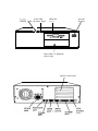
You may want to open this manual’s back cover foldout so you
can refer to the illustrations identifying the different parts.
Setting Up Your System
1-2
1
Choosing a Location
When selecting a place to set up your system, choose a safe,
convenient location that provides the following:
1-2
0
A flat, hard surface. Surfaces like beds and carpets attract
static electricity, which can erase data on your disks,
damage the computer’s circuitry, and prevent proper
ventilation.
0
Good air circulation. Leave several inches of space around
the computer so air can move freely.
Ll
Moderate environmental conditions. Select a cool, dry area
and protect your computer from extremes in temperature,
humidity, dust, and smoke. Avoid direct sunlight or other
sources of heat.
0
No electromagnetic interference. Do not place your system
too close to any electrical device, such as a telephone or
television, which generates an electromagnetic field.
c3
Appropriate power source. Connect all your equipment
with the appropriate power cords for the power source in
your area. If you are operating the computer in a country
other than the one in which you purchased it, see “Power
Source Requirements” in Appendix A of the User’s Guide
for a list of the cords you should use.
Setting Up Your System
2
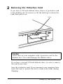
Removing the Protective Card
If you have a 5.25-inch diskette drive, there is a protective card
in the diskette slot. To remove it, lift the latch up to release the
card; then pull it out.
latch
Caution
Never turn on your computer with a protective card in the
diskette slot. You could damage the diskette drive.
If you have a second 5.25-inch diskette drive, be sure to remove
the card from it also.
Save the protective card. If you transport your computer later,
insert the card to protect the drive’s read/write heads during
shipping.
Setting Up Your System
1-3
3
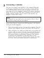
Connecting a Monitor
The way you connect your monitor to the computer depends
on the type of monitor you have. If you have a VGA monitor
(or a multifrequency monitor with an analog connector), you
can connect it to the computer’s built-in VGA port as described
below. If you have any other type of monitor (or if you want to
install a display adapter card to control your monitor), see
Chapter 2 of the User’s Guide.
Note
If a manual was provided with your monitor, refer to those
instructions along with the ones below.
Follow these steps to connect your VGA monitor to the built-in
VGA port on the computer:
1. Place your monitor on top of or near the computer. Turn the
monitor and computer around so the backs are facing you.
2.
1-4
There should be two cables provided with your monitor: the
monitor cable (to connect it to the computer) and the power
cable (to connect it to a power source). On most monitors,
the monitor cable is permanently attached to the monitor,
as shown in the illustration on the next page. If your
monitor does not have an attached cable, connect the cable
to it now. (See your monitor manual for instructions.)
Setting Up Your System
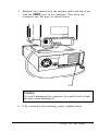
3. Examine the connector on the monitor cable and line it up
with the VIDEO port on the computer. Then insert the
connector into the port, as shown below.
VIDEO
Caution
To avoid damaging the connector, be careful not to bend
the pins when inserting it.
4. If the connector has retaining screws, tighten them.
Setting Up Your System
1-5
5. Plug the monitor power cord into the monitor’s power inlet,
as shown below.
monitor power inlet
6. Plug the other end of the power cord into an appropriate
grounded (earthed) electrical outlet.
1-6
Setting Up Your System
4
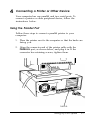
Connecting a Printer or Other Device
Your computer has one parallel and two serial ports. To
connect a printer or other peripheral device, follow the
instructions below.
Using the Parallel Port
Follow these steps to connect a parallel printer to your
computer:
1.
Place the printer next to the computer so that the backs are
facing you.
2. Align the connector end of the printer cable with the
PARALLEL port, as shown below, and plug it in. If the
connector has retaining screws, tighten them.
ML
PARALLEL
Setting Up Your System
1-7
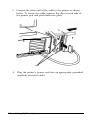
3.
Connect the other end of the cable to the printer as shown
below. To secure the cable, squeeze the clips at each side of
the printer port and push them into place.
clips
4. Plug the printer’s power cord into an appropriate grounded
(earthed) electrical outlet.
1-8
Setting Up Your System
Using the Serial Ports
If you have a printer, a modem, or other peripheral device with
a serial interface, you can connect it to one of the serial
(RS-232C) ports on the back of the computer. These ports use a
DB-9P connector, so be sure you have a compatible cable.
To connect a serial device, insert the connector into one of the
ports, marked SERIAL 1 and SERIAL 2. If you are connecting only
one serial device, use the SERIAL 1 port, as shown below.
SERIAL 1
Setting Up Your System
1-9
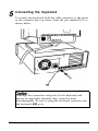
Connecting the Keyboard
To connect the keyboard, hold the cable connector so the arrow
on the connector faces up. Insert it into the port marked K/B, as
shown below.
Although the connectors and ports for the keyboard and
mouse are physically identical, they cannot be used
interchangeably. Be sure to plug the keyboard connector into
the keyboard (K/B) port.
1-10
Setting Up Your System
You can change the angle of the keyboard by adjusting the legs
on the bottom. Turn it over and flip each leg upward until it
locks into place. It is important to select the best angle so you
will prevent wrist fatigue. (You may even want to purchase a
wrist pad--sold at computer stores-for further comfort.)
To lower the keyboard, press each leg back into its slot.
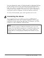
Connecting the Mouse
Your computer has an auxiliary port for an IBM® PS/2™
compatible mouse that uses a round, miniature DIN (6-pin)
connector. If your mouse has this type of connector, you can
connect it to the computer’s built-in port.
Note
If your mouse requires a different interface port, you can
connect it to the built-in serial port or install an option card
that provides the interface. When your system loads the
mouse driver, it will properly identify the location of your
mouse.
Setting Up Your System
1-11
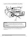
To connect a mouse to the built-in mouse port, plug the
connector into the port marked MOUSE, as shown below.
l
Iris
-
Caution
Although the connectors and ports for the mouse and
keyboard are physically identical, they cannot be used
interchangeably. Be sure to plug the mouse connector into
the MOUSE port.
If your system has not already been configured, you may need
to install a mouse driver. See your mouse manual for
instructions.
1-12
Setting Up Your System
7
Connecting the Power Cord
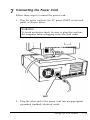
Follow these steps to connect the power cord:
1.
Plug the power cord into the AC power INLET on the back
panel, as shown below.
WARNING
To avoid an electric shock, be sure to plug the cord into
the computer before plugging it into the wall outlet.
2.
Plug the other end of the power cord into an appropriate
grounded (earthed) electrical outlet.
Setting Up Your System
1-13
8
Turning On the Computer
After you set up your system, you’re ready to turn on the
power. Follow these steps:
1.
Turn your computer around so the front panel faces you and
place your other system devices (monitor, printer, etc.) in a
convenient arrangement.
2.
Turn on the monitor, printer, and any other devices connected
to the computer.
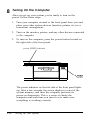
3. To turn on the computer, press the power button located on
the right side of the front panel.
power (SPEED) indicator
button
The power indicator on the left side of the front panel lights
up. After a few seconds, the screen displays a count of the
system memory, and then the computer performs its
power-on diagnostics. This is a series of checks the
computer runs each time you turn it on to make sure
everything is working correctly.
1-14
Setting Up Your System
4. If necessary, use the controls on your monitor to adjust the
brightness and contrast until characters on the screen are
clear and at a comfortable level of intensity. If your monitor
has horizontal and vertical hold controls, you may need to
use them to stabilize the display.
5. The screen displays the following prompt:
Press Del to start SETUP
Do not press any key yet; you just want to make sure the
computer is working. This prompt appears every time you
turn on your computer so you can run SETUP if necessary.
After a few seconds, the prompt disappears.
If there is no operating system installed on your computer, you
then see an error message. Ignore the message for now;
once you install the operating system, you will not see this
message. If MS-DOS® is already installed, you may see the
command prompt (C : \) or the menu screen of a program
such as Windows, if it has been configured to do this.
Where To Go Next
If your system is preconfigured, the only thing you need to do
now is install any additional software and VGA device drivers
you want to use. (See your application program manuals for
instructions on installing software.) If you are using Microsoft
Windows?, be sure to install the appropriate VGA driver(s) for
your monitor. See the VGA Utilities Guide for instructions. Then
see Chapter 1 of the User’s Guide for important information
about operating your computer.
If your system is not preconfigured, follow the instructions in
Chapter 2 to run the SETUP program. Guidelines at the end of
Chapter 2 tell you what to do next.
Setting Up Your System
1-15
Chapter 2
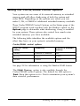
The first time you use your computer, you need to run the
SETUP program to define how your system is set up. You may
need to run it again later if you change your configuration.
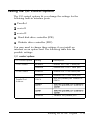
The SETUP program is stored in the computer’s read-only
memory (ROM), so you can run it any time you turn on or reset
your computer. SETUP lets you verify or change the following:
a
Current date and time
a
Type of diskette drive(s) installed
a
Type of video display adapter you are using
cl
Self test error level
a
Cache
a
Shadow RAM and additional extended memory usage
a
Password feature
a
Type of hard disk drive(s) installed
a
System memory
a
System booting sequence
a
virus warning
a
Nun-Lock setting for system startup
a
Bus control options
a
I/O control options.
Running the SETUP Program
2-1
The configuration you define through SETUP is stored in a
special area of memory called CMOS RAM. This memory is
backed up by a battery, so it is not erased when you turn off or
reset the computer. Whenever you reboot the computer, it
checks the settings, and if it discovers a difference between the
information in the CMOS RAM and its actual hardware
configuration, it prompts you to run SETUP. You see a message
such as the following:
FLOPPY DISK TYPE IS SET INCORRECTLY OR
DRIVE ERROR
You also see the following prompt at the bottom of the screen:
Press Fl
to continue or Del
to start SETUP
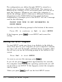
If this happens, press [Ddetbl to run SETUP and correct the
setting.
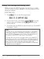
Starting the SETUP Program
To start SETUP, make sure there is no diskette in the diskette
drive; then turn on your computer. (If your computer is already
on, turn it off, wait 20 seconds, and then turn it on again.) After
the self test, you see the following prompt at the bottom of the
screen:
Press Del
to start SETUP
As soon as you see this message, press loektel.
If you do not press m within approximately five seconds,
the computer starts loading the operating system and you will
not be able to run SETUP. If this happens, restart the computer
and try again.
When you press [Iklete), you’ll see the first SETUP screen.
2-2
Running the SETUP Program
Note
If you are using a monochrome monitor and are having
trouble seeing your cursor position, press [F21 to change
the screen colors. Your cursor changes to a solid highlight
bar over the option.
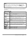
The table below lists the keys you can use to perform SETUP
operations.
Key
Function
Displays a help screen describing some of the keys you
can use with the program
lFIl
Displays a help screen describing the option currently
selected
[nl
Changes screen colors; if you have a color monitor,
pressing this key changes the display from color to
monochrome or monochrome to color
Displays the exit menu so you can exit the SETUP
program
Moves the cursor to the next modifiable option
r;l or FJ
Changes the current setting; for numeric parameters,
increases or decreases the current numeric value
I‘r;ors
Moves the cursor to the next option window
(on numeric
keypad)
Displays the Options Page
Displays the Status Page
Running the SETUP Program
2-3
Setting the Date and Time
The real-time clock in your computer continuously tracks the
date and time-even when the computer is turned off. Once
you set the date and time using SETUP, you should not need to
change them, unless you need to adjust the time for daylight
savings or other seasonal adjustments. (The computer
automatically changes the date for leap years.)
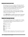
Use the cursor arrow keys to position the cursor over the
portion of the date or time you want to change. For the date
option, you can change the first two digits of the year field
separately from the last two digits.
Use the r;-] or m keys to modify the date or tune. You can also
type numbers into the fields that accept numbers. Change the
tune using a 24-hour clock. For example, 5 pm. would be 17.
Setting the Diskette Drive(s)
Your system probably came with one diskette drive installed
and you may have another drive of a different size or capacity.
The SETUP menu offers five possible selections for your
diskette drives (A and B):
Cl 360KB, 5.25-inch
Cl 1.2MB, 5.25-inch
Cl 720KB, 3.5-inch
Cl 1.44MB, 3.5-inch
Ll None.
Check the settings for both drives and correct them if necessary.
(If you have only one diskette drive, select None for drive B.)
2-4
Running the SETUP Program
Setting the Video Display Type
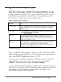
The Video option lets you define the type of adapter you are
using for your primary display. If you connected your monitor
to the computer’s built-in VGA port, select EGA/VGA. If you
installed an optional video card, follow the guidelines in the
table below to select the correct adapter type.
Video display type options
I
l
Select
If
EGA/VGA
You connected your monitor to the built-in VGA port or
you installed a VGA or enhanced graphics adapter
(EGA) card
CGA40
You installed an optional color graphics adapter that is
I set to 4C-column CGA mode
CGA80
You installed a color graphics adapter (CGA) or a
multi-mode graphics adapter (MGA) attached to a
color monitor; be sure to set the color/mono switch on
the MGA card to color
MONO
You Installed a monochrome display adapter (MDA).
an MGA, or a Hercules® MGA attached to a
monochrome monitor; be sure to set the color/mono
switch on the MGA card to mono
Default setting
For a composite color monitor, such as a color television with a
video input, try selecting CGA 80. If the monitor’s resolution is
poor, run SETUP again and select CGA 40.
If you have two display adapters of different types, select the
setting for the one you want to be your primary display
adapter. The other one is your secondary adapter.
If you installed an EGA display adapter card, or another type of
card that you want to be the primary display adapter, you must
set jumper J6 on the main system board to position 2-3 to
disable the built-in VGA interface.
Running the SETUP Program
2-5
If you install one type of display adapter card and then change
the adapter (from VGA to CGA or vice-versa), you also may
need to set jumper J5. If you have two types of cards, set the
jumper to match the adapter controlling your primary display.
See Chapter 2 in the User’s Guide for instructions on changing
jumper settings and the manual that came with your monitor
for additional information.
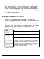
Setting the Self Test Error Level
When you start your system, it performs a self test. The
H a l t on option determines the point at which the system will
stop if it finds an error during the self test.
If your computer is running without a keyboard or diskette
drive or it must always start, you can choose one of the options
in the following table to ensure the computer will boot.
Self test error levels
It
You want your system to stop booting if it encounters
any errors during the self test
You don’t want your system to stop booting, even If it
encounters errors during the self test
You want your system to stop booting if it encounters
any error except a keyboard error during self test
You want your system to stop booting if it encounters
any error except a diskette drive error during self test
You want your system to stop booting if it encounters
any error except either a diskette drive error or a
keyboard error during self test
Default setting
2-6
Running the SETUP Program
Setting the Cache
Your computer comes with an 8KB internal memory cache built
into the microprocessor. The SETUP program allows you to
disable or enable the internal cache, as shown in the following
table.
Cache options
select
If
1
internal Cache
You want to use your system’s internal cache
I
Disabled
You do not want to use the internal cache
It is best to leave the cache enabled so your system performs
most efficiently.
Setting the Shadow RAM
Your computer can access RAM (random access memory) faster
than ROM (read only memory). The Shadow feature allows
your system to copy the contents of its system BIOS and/or
video BIOS into RAM so it can perform certain operations
faster.
Your system automatically enables shadow RAM for both the
system BIOS and the video BIOS. You may need to disable one
or both shadow options, however, if you install an option card
(such as a SCSI card) that locates its RAM in one of these areas.
Running the SETUP Program
2-7
The Shadow options let you choose what to place in the
shadow RAM area.
Shadow RAM options
Select
If
System BIOS
You want to copy only your system BIOS into RAM
Video BIOS
You want to copy your video BIOS into RAM
System &
Video’
You want to copy both your system and video BIOS into
RAM
Disabled
You don’t want to use Shadow RAM
Default setting
If you want to use any but the default settings for the system or
video shadow RAM, you must change the Video and System
cacheable settings on the Status page in addition to changing
the Shadow RAM option here. Use the following table to set
your Shadow RAM feature.
Valid shadowing options
I
Options page
I
Status-page
I
Shadow option
Video cacheable
option
system cacheable
option
Disabled
Disabled
Disabled
System only
Disabled
Enabled
Video only
Enabled
Disabled
System & video
I Enabled
I
Enabled
See page 2-21 for more information on setting the Video and
System cacheable options.
2-8
Running the SETUP Program
I
I
Setting the Password (Security) Options
The SETUP program lets you enter, change, or disable an
optional password to control who can access your system. The
following table lists the available options.
Security options
Select
If
Disable
You do not want to set a password
Setup Access
You want to set a password to use the SETUP program
System Access
You want to set a password to use the system
(computer) including the SETUP program
Default setting
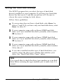
If you select Setup Access, you’ll see the password prompt
only when you use the SETUP program. If you select system
Access, you’ll see the password prompt both for the SETUP
program and whenever the computer boots (loads the
operating system).
Follow these steps to enter a password:
1. Move your cursor to the security option.
2
Use [-I or [+1 to select either Setup Access or
System Access. The menu at the bottom of the screen
now contains the following prompt:
<Enter> to Set/Change Password
3 . Press@@.
4. You’ll see the following prompt in a window at the center of
the screen:
Enter Password:
Running the SETUP Program
2-9
5. Enter the password you want to use. As you type the
password, the screen displays an asterisk for each letter.
Then you see this prompt:
Confirm Password:
Again, you’ll see an asterisk for each letter you type.
If the password you type the second time doesn’t match the
first password you entered, you see the Enter Password:
prompt again.
6.
As you exit the SETUP program, make sure you save the
new settings. If you set the System Access password, when
the system reboots you will see the password prompt.
Changing or Deleting a Password
If you want to change one of the Password options, follow
the same steps as to enter a new one. When you see the
Enter Password : prompt, just type the new password you
want to use.
If you want to delete a password, move your cursor to the
Security option and press I+] or [-) until you see the
Disabledoption.
Whenever you change or delete your password using the
SETUP program, make sure you save the new settings as you
exit the program.
2-10
Running the SETUP Program
Setting the Hard Disk Drive(s)
The SETUP program lets you select the type of hard disk
drive(s) installed in your computer. If you have two hard disk
drives, the first one is C and the second one is D. Be sure to
choose the correct setting for both drives.
Follow these guidelines:
0
If your system does not have a hard disk, select None for
drives C and D. If you have only one hard disk drive, select
None for drive D.
0
If your computer came with an Epson 80MB hard disk
drive (or if you installed this drive yourself), select number
24 for drive C.
0
If your computer came with an Epson 120MB hard disk
drive (or if you installed this drive yourself), select number
39 for drive C.
0
If your computer came with an Epson 240MB hard disk
drive (or if you installed this drive yourself), select number
34 for drive C.
0
If you have installed another type of hard disk drive, you
need to select the drive type number that matches your
drive. See “Hard Disk Drive Types” below.
Note
It is a good idea to check the drive type number on your disk
drive before entering the type number, just to make sure it is
correct.
Running the SETUP Program
2-11
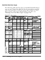
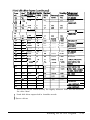
Hard Disk Disk Drive Types
The following table lists the types of standard hard disk drives
you can use. Check this table and the documentation supplied
with your hard disk to find the correct type number for your
drive. If none of the types listed matches your drive, see
“Defining Your Own Drive Type” on page 2-14.
Hard disk drive types
VW She' cyhdea Heacb seclom
(In MB) CW
no.
lmdlng
Drlvenanw/
nKmulactl8eI
(Ius) 6Ec) Precomp z o n e
1
10
306
4
17
128
305
2
20
615
4
17
300
615
615
6
17
300
615
940
8
17
512
940
ST-225,STdM6,
wD-93024
t
940
6
17
512
940
20
615
4
17
norm
615
7
30
462
8
17
256
8
130
l--l-6
none
ST-138At
CP-Xt24,ST-125.
ST-125A,%325A
511
S-4038
1733
none 1 855
16
20
612
4
17
40
977
5
17
18
CPa44t.
CP-2Q44 t.704ot.
8Ck5lAt
56
977
7
-77
19
59
1024
7
17
512
1023
CP-2064
20
30
733
5
17
3ccl
732
MK-133FA
21
42
733
7
17
300
732
MK-134FA,ST-157At
22
30
733
5
17
3al
733
23
10
306
4
17
0
336
I=
t
2-12
0
Running the SETUP Program
none
1
1
Wpe
ad
no.
QnMlD
24
81
cykden
(cn)
903
25
100
t
776
1
26
Drke name/
4
CP-?Jx84 t
8
CP-3104
-reserVd-
27
40
698
28
40
976
- reserved -KlS0IWd-
29
*
732
1023
17
lnone
116
901
34
234
723
35
124
934
16
37
202
683
16
CP-3204F
38
81
548
8
CP-2084
761
8
CP-30104
LPSl2UATt
LP324OATt
MK2124FC
-reserved-
36
39
115
40
81
~ 980
41
84
I1022
5
CDC9421&106
(ESDI)
42
89
1022
15
CDC94216106
68
1024
8
1325,3D%.lAN64.
XT1085,NDRlO%
44
137
828
10
MK-156F
45
42
1024
I5
46
40
615
~ 8
43
l
I1023
33
47
-resewed-
48
-userdefined-
49
-merdefimd-
Actual size when formatted
the drive label
may
be slightly different than the size listed on
t Hard disk drive supported in translate mode
t Epson drives
Running the SETUP Program
2-13
Defining Your Own Drive Type
If the parameters for your hard disk (listed in its
documentation) do not match any of the types listed in the table
above, you can define your own type. Follow these steps:
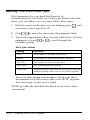
1. With the cursor on the drive you are defining, press [-1 until
you come to drive type 48 or 49.
2.
Press m to move the cursor into the parameter fields.
3. Type in the appropriate values from the table below for these
parameters or press r;] or [-1 to scroll through the
available options.
Drive type options
Heading
Description
CYLS
The number of cylinders on the drive
HEADS
The number of read/write heads in the drive
SECTORS
The number of sectors on the drive
PRECOMP
The precompensation cylinder
LANDZONE
The landing zone (the area on which the computer
parks the heads when you run the HDSlT program)
Press I-1) after typing each number. Check your drive
documentation for the correct value if the SETUP program
does not accept a value you’ve typed.
SETUP provides the hard disk size based on the other values
you entered.
2-14
Running the SETUP Program
Checking System Memory
Your computer comes with 4MB of random access memory.
MS-DOS and application programs that run under MS-DOS use
the first 640KB of memory. You can use the memory above
1MB as extended or expanded memory.
Expanded memory can be used by application programs
conforming to the Lotus~/Intel@‘/Microsoft Expanded Memory
Specification (LIM EMS). Your computer is compatible with
version 4.0 of the LIM EMS.
The Memory portion of the SETUP program’s first screen
displays the total memory available and the amount of memory
contained in each of the following:
Q Basememory
Ll Extended memory
Cl Expanded memory
0
Reserved memory between 640KB and 1MB.
Setting the Booting Sequence
The booting sequence determines the order in which the
computer checks the drives when it looks for the operating
system.
For example, if you select A, C, each time you turn on the
computer it checks drive A for an operating system diskette
and loads the operating system from that diskette. If drive A
does not contain an operating system diskette, the computer
loads the operating system from drive C. This is the default
setting because you may sometimes want to boot the computer
from a system diskette in drive A.
Running the SETUP Program
2-15
If you select C, A, the computer loads the operating system
from drive C. If it doesn’t find the operating system on drive C,
it checks the diskette in drive A. This setting allows the
computer to load the operating system a little faster.
Setting the Virus Warning
Your computer contains a built-in virus warning function to
protect your data should a software virus come in contact with
your system.
If the virus Warning option is enabled, the system displays a
virus warning message when it detects a program attempting
to write to the boot sector on either a diskette or the hard disk
drive. You must respond to a prompt either to allow a
legitimate program (such as the MS-DOS FORMAT command)
to write to the boot sector or to deny access to a program that
shouldn’t be writing to the boot sector.
If you install an operating system, it writes to the boot sector as
you install it. In this case, you probably do not want the virus
warning feature enabled. Therefore, your system initially has the
virus warning feature disabled. This way you won’t need to
respond to the virus warning prompts if you install an
operating system. Once you have installed it, you can enable
this option to take advantage of the virus warning feature.
2-16
Running the SETUP Program
Setting the NumLock Boot Status
The NumLock Boot Status option allows you to select the
initial state of the num lock function when you turn on or reset
your system. When num lock is off, the keypad controls cursor
movement. If num lock is on, the keypad types numbers. You
can also change the num lock function by pressing the [v
key. An indicator light on the keyboard shows when this
function is turned on.
You can select On or Off for the NumLock Boot Status
option; the default setting is on
Setting the Bus Control Options
The Bus Control options determine how your system handles
data processing. Your system default settings have been
selected to provide the most efficient operation; however, you
may want to change certain settings to optimize the
performance of your configuration.
Running the SETUP Program
2-17
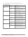
The following table lists the possible optional settings.
Bus control options
Bus control option
Setting
Description
ISA Command
Delay
Normal*
Allows your system to rug at Its
fastest speed
Extended
Provides a delay to correct
timing problems you may have
when your system contains a
slower option card
Normal*
Uses 0 wait states, providing the
fastest processing
Extended
Provides a wait state for when
you are accessing slower option
cards or diskette drives
Enabled
Provides compatibility with
slower memory, for instance,
with some slower LAN cards
Disabled*
Allows your system to access
memory at lts fastest speed
Enabled
Works with the I/O recovery time
to provide compatibility with
slower memory
Disabled*
Allows your system to access
memory at its fastest speed
ISA Wait State
I/O Recovery Time
Extended ALE
Decouple Refresh Enabled
Disables
l
2-18
Default setting
Running the SETUP Program
DRAM operation continues
during ISA bus refresh
DRAM operation is stopped
during ISA bus refresh; this system
uses a fast ISA bus so you’ll want
to keep this option disabled
Setting the l/O Control Options
The I/O control options let you change the settings for the
following built-in interface ports:
0 Parallel
Ll serial1
0 serial2
0
Hard disk drive controller (IDE)
Cl
Diskette drive controller (FDC).
You may need to change these settings if you install an
interface on an option card. The following table lists the
possible settings.
I/O control options
I/O control option
Setting
1 Description
COM1 Select
Enabled*
I Enables the COM 1 serial port
Disabled
I Disables the COM 1 serial part
Enabled*
Enables the COM2 serial part
Disabled
Disables the COM2 serial part
O3BCH
Sets the parallel part address to
03BCH
COM2 Select
Parallel Port
Address
Disabled
I Disables the parallel port
Running the SETUP Program
2-19
I/O control options (continued)
I/O control option
Setting
Description
IDE Select
Enabled
Uses the Internal hard disk
controller
I
Disables the internal hard disk
controller
I
Disabled
FDC Select
Enabled*
Disabled
l
Default setting
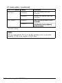
Note
If you want Serial Port 2 to be the primary port, you must
disable COM1 and enable COM2 here.
2-20
Running the SETUP Program
Setting the Cache/DRAM Control Options
Your system can use some of ifs reserved memory as extended
memory and still allow shadowing of both the system and
video BIOS. Depending on the options you select, you can
make 0, 256, or 384KB of additional extended memory available.
Three Cache/DRAM Control Options on the Status page of the
SETUP program work together with the Shadow option on the
Options page to determine what shadowing, if any, is enabled
for your system. These options also control how much extra
extended memory you have available.
The following fable identifies the available options and the
effect they have on your system’s extended memory.
Cache/DRAM control options
256/384 relocate
Shadowing
Increase In extended
memory
Disable
Enabled or Disabled
0KB
Enable
Enable
256KB
Enable
Disable
384KB
setting
See page 2-8 for information on using the Shadow RAM feature.
The DRAM Timing option is also available through the
Cache/DRAM control options. The default for this option is
Fast. Keep this option set to Fast to maximize your system’s
data retrieval performance.
Running the SETUP Program
2-21
Saving Your Settings and Exiting SETUP
When you leave the SETUP program, you can choose to either
save the settings you have changed or exit the program without
saving any changes.
Follow these steps:
1.
Press [F10 You see the following prompt:
PRESS F5 TO SAVE AND EXIT
PRESS F1 TO EXIT W/O SAVE
2.
If you want to save your changes, press m If you don’t
want to save your changes, press b
Either way, the
Fl
system reboots.
3.
If you have just run SETUP for the first time, see “Post-SETUP
Procedures,” below.
Note
You may see an error message and a prompt to run SETUP
when your computer is rebooting if it detects a problem in
your SETUP configuration. If so, follow the instructions on
the screen to run SETUP and correct the problem.
You may also see an error message when your computer is
rebooting if you have not installed your operating system on
the hard disk and you have not inserted a system diskette in
drive A. If you receive this error message, follow the
instructions in your operating system manuals to install the
software on your computer.
2-22
Running the SETUP Program
Post-SETUP Procedures
If you have just run SETUP for the first time and your system
has not been configured, you now need to install the operating
system on your computer. See your operating system manuals
for instructions.
After you have installed your operating system, you can install
any software you plan to use. See your application program
manuals for instructions.
If you are going to install Microsoft Windows, be sure to also
install the Windows VGA driver(s) as appropriate for your
monitor. See the VGA Utilities Guide for instructions.
Running the SETUP Program
2-23
Appendix A
Using Memory
Your computer comes with 4MB of memory, and you may have
installed additional memory. This appendix describes how the
memory in your computer works and gives guidelines for
using the appropriate memory manager program to control
your memory.
Types of Memory
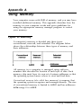
A computer’s memory is divided into three types:
conventional, reserved, and extended. The diagram below
shows the relationships between these types of memory and
their addresses.
All memory in a computer is managed using addressesnumbers that describe the location of each byte of data. Each
memory chip must have its own set of unique addresses so that
the operating system knows where to store and find data.
Conventional memory (also called base memory) is memory that
the operating system recognizes and manages directly. The size
of conventional memory is limited to 640KB and has addresses
in the range 0 to 640KB.
Using Memory A-1
Reserved memory is addressable memory in the range 640KB to
1MB. Normally, a video card or option card must provide the
physical RAM for these addresses. The system can enhance its
performance by using 128KB of this extra memory as shadow
RAM. Some of the remaining memory may be available; see
Appendix A of the User’s Guide for in&nation on how your
computer uses this memory.
Extended memory is memory with addresses in the range 1MB to
the maximum system memory, and can be used only by the
following:
0
Certain operating systems, such as OS/2®
0
Some MS-DOS interfaces, such as Windows
0
Some RAM disk programs, such as VDISK
0
Some hard disk caching programs, such as SMARTDRV
0
Certain specially-written, protected mode MS-DOS
applications.
Most versions of MS-DOS include a standard extended
memory manager. If you are using MS-DOS, Windows, and
other compatible programs, it is best to use one of the memory
managers (such as HIMEM.SYS) that came with your software
because these memory managers have been tested and proven
reliable.
Most MS-DOS commands and application programs cannot use
extended memory directly. They need to use expanded memory.
This type of memory allows some MS-DOS applications to get
around the 640KB limitation. You control expanded memory
with a memory manager (such as EMM386.EXE), which enables
the computer to use your extended memory as expanded
memory.
A-2 Using Memory
For more information about your system’s memory, see the
“System Memory Map” in Appendix A of the User’s Guide.
For instructions on using your memory manager, see the
documentation that came with it.
Note
Microsoft Windows comes with its own memory manager;
be sure to install it if you use Windows and your system is
not preconfigured. (See your Windows documentation for
instructions.)
Using Memory A-3
Index
A
AC power inlet, 1-13
Addresses, 2-19, A-1-2
Air circulation, 1-2
ALE, extended, 2-18
Analog connector, 1-4
Application programs, 1-15,
2-15-16, 2-23, A-2
Auxiliary port, 1-11
B
Base memory, 2-15, A-1
Battery, 2-2
BIOS, 2-7-8, 2-21
Booting sequence, system, 2-1,
2-15-16
Booting system, 2-6, 2-15-16,
see also Turning on computer
Boot sector, 2-16
Built-in port, see Port
Bus control options,
setting, 2-1, 2-17-18
C
Cable,
keyboard, 1-10
modem, 1-9
monitor, 1-4-5
mouse, 1-11-12
power, see Power cord(s)
printer, 1-7-8
serial device, 1-9
Cache/DRAM control options,
setting, 2-21
Cache, setting, 2-1, 2-7
Cards(s),
display adapter, 1-4, 2-1, 2-5-6, A-2
option, 1-11, 2-7, 2-18, 2-19, A-2
protective, 1-3
video, 1-4, 2-1, 2-5-6, A-2
CGA (color graphics adapter),
2-5-6
Changing password, 2-9-10
Checking system memory, 2-15
Choosing location, 1-2
Clock, real-time, 2-4
CMOS RAM, 2-2
Color monitor, 2-3, 2-5-6
Color television, 2-5
COM1 and COM2 , 2-19-20
Command prompt, 1-15
Composite color monitor, 2-5
Configuration, Intro-1, 2-1-2, 2-17,
2-22
Connecting,
keyboard, 1-10-11
modem, 1-9
monitor, 1-4-6
mouse, 1-11-12
power cord(s), 1-2, 1-4, 1-6, 1-8,
1-13
printer, 1-7-9
serial device, 1-9
Connectors,
analog, 1-4
keyboard, 1-10, 1-12
monitor, 1-5
mouse, 1-10, 1-12
printer, 1-7
serial device, 1-9
video, 1-5
Controllers, disk drive, 2-19-20
Conventional memory, A-1
Cursor, 2-3, 2-17
Index
1
D
Date, setting, 2-1, 2-4
DB-9P connector, 1-9
Default settings, SETUP program,
booting sequence, 2-15
bus control, 2-17-18
cache, 2-7
I/O control, 2-19-20
num lock, 2-17
password, 2-9
security, 2-9
self test error level, 2-6
shadow RAM, 2-8
video display type, 2-5
Defining drive type, see Diskette
drive type(s) or Hard disk drive
type(s)
Delay, ISA command, 2-18
Deleting password, 2-10
Diagnostics, power-on, 1-14
Disk drive controllers, 2-19-20
Diskette boot sector, 2-16
Diskette drive,
booting sequence, 2-15-16
controller, 2-19-20
protective card, 1-3
self test error level, 2-6
setting, 2-4
slower, 2-18
type(s), 2-1, 2-4
Display adapter, 1-4, 2-1, 2-5-6, A-2
DRAM, 2-18, 2-21
Driver(s),
mouse, 1-11-12
VGA, 1-15, 2-23
Drives, see Diskette drive or
Hard disk drive
E
EGA (enhanced graphics adapter),
2-5
Electromagnetic interference, 1-2
EMM386.EXE, A-2
2
Index
Environmental conditions, 1-2
Error level, self test, 2-1, 2-6
Error messages, 1-15, 2-2, 2-22
Exiting SETUP, 2-3, 2-10, 2-22
Expanded memory, 2-15, A-2
Extended memory, 2-1, 2-15, 2-21,
A-1-2
F
FDC, 2-19-20
FORMAT command, 2-16
H
Hard disk drive,
booting sequence, 2-15-16
boot sector, 2-16
caching programs, A-2
controller, 2-19-20
defining your own drive type, 2-14
Epson hard disk drives, 2-11
setting, 2-11-14
type(s), 2-1, 2-11-14
type number, 2-11-13
Heads, read/write, 1-3
Help screen, SETUP, 2-3
Hercules MGA, 2-5
Highlight bar, 2-3
HIMEM.SYS, A-2
I
IDE, 2-19-20
Indicator, power, 1-14
Inlet, AC power, 1-13
Installing operating system and
software, Intro-1, 1-15, 2-22-23
Interface, see Port
Interference, electromagnetic, 1-2
Internal cache, 2-7
Internal drive controllers, 2-20
I/O control options, setting, 2-1,
2-19-20
I/O recovery time, 2-18
J
Jumper settings, 2-5-6
K
Keyboard,
adjusting angle, 1-11
cable, 1-10
connecting, 1-10-11
legs, 1-11
num lock, 2-1, 2-17
port, 1-10,1-12
self test error level, 2-6
SETUP function keys, 2-3
Keypad, 2-17
Keys, SETUP function, 2-3
L
LAN cards, 2-18
Leaving SETUP program, 2-22
LIM EMS, 2-15
Location, choosing, 1-2
M
Manager, memory, A-13
Map, memory, A-3
MDA (monochrome display
adapter), 2-5
Memory,
addresses, 2-19, A-1-2
base, 2-15, A-1
cache, 2-1, 2-7, 2-21
CMOS RAM, 2-2
conventional, A-1
count, 1-14
expanded, 2-15, A-2
extended, 2-1, 2-15, 2-21, A-1-2
LIM EMS, 2-15
manager, A-1-3
map, A-3
RAM, 2-7-8, 2-15, A-2
relocate setting, 2-21
reserved, 2-15, 2-21, A-1-2
ROM, 2-1, 2-7
Memory,
shadow RAM, 2-1, 2-7-8, 2-21, A-2
system, Intro-1, 1-14, 2-7-8, 2-15,
2-21, A-1-3
types, A-1-3
Messages, error, 1-15, 2-2, 2-6, 2-22
MGA (multi-mode graphics
adapter), 2-5
Modem, connecting, 1-9
Monitor,
brightness, 1-15
cables, 1-4-6
CGA, 2-5-6
color, 2-3, 2-5-6
connecting, 1-4-6
contrast, 1-15
EGA, 2-5
horizontal and vertical hold, 1-15
monochrome, 2-3, 2-5
multifrequency, 1-4
port, VGA, 1-4-5, 2-5
power cord, 1-4, 1-6
screen colors, SETUP, 2-3
VGA, 1-4-6, 2-5-6
Monochrome monitor, 2-3, 2-5
Mouse, 1-11-12
MS-DOS, 1-15, 2-15-16, A-2
Multifrequency monitor, 1-4
N
Num lock, 2-1, 2-17
O
Operating system,
booting sequence, 2-15-16
command prompt, 1-15
installing, Intro-1, 1-15, 2-16,
2-22-23
loading, 2-2, 2-15-16
Option cards, 1-11, 2-7, 2-18, 2-19,
A-2
Options page, 2-3, 2-8, 2-21
OS/2, A-2
Index
3
P
Parallel port, 1-7-8, 2-19
Password, 2-1, 2-9-10
Port,
addresses, parallel 2-19
built-in VGA, 1-4-5, 2-5
keyboard, 1-10, 1-12
monitor, 1-4-5, 2-5
mouse, 1-11-12
parallel, 1-7-8, 2-19
primary, serial, 2-20
serial, 1-9, 2-19-20
VGA, built-in, 1-4-5, 2-5
VIDEO, 1-5
Post-SETUP procedures, 2-22-23
Power,
button, 1-14
cord(s), 1-2, 1-4, 1-6, 1-8, 1-13
indicator, 1-14
inlet, 1-6, 1-13
source, 1-2, 1-4
Power-on diagnostics, 1-14
Preconfigured system, Intro-1, 1-15
Primary display adapter, 2-5-6
Primary serial port, 2-20
Printer,
connecting, 1-7-9
parallel, 1-7-8, 2-19
serial, 1-9, 2-19-20
Programs, application, 1-15, 2-16,
A-2
Prompt, SETUP, 2-2
Protected mode, A-2
Protective card, 1-3
R
RAM (random access memory),
2-7-8, 2-15, A-2
Read This First card, Intro-1
Read /write heads, 1-3
Real-time clock, 2-4
Rebooting computer, 2-2, 2-10, 2-22
Refresh, decouple, 2-18
4
Index
Removing protective card, 1-3
Reserved memory, 2-15, 2-21,
A-1-2
Resetting computer, 2-1-2, 2-17
Resolution, 2-5
ROM (read only memory), 2-1, 2-7
RS-232C, 1-9
S
Saving SETUP settings, 2-10, 2-22
Screen, see Monitor
SCSI card, 2-7
Secondary display adapter, 2-5
Security options, setting, 2-9-10
Self test, 2-2, 2-6, see also Power-on
diagnostics
Self test error level, setting, 2-1, 2-6
Serial,
COM1 and COM2, 2-19-20
device, connecting, 1-9
ports, 1-9, 2-19-20
Setting up system, Intro-1, 1-1-15
Setup Access password, 2-9
SETUP program,
base memory, 2-15
booting sequence, system, 2-1,
2-15-16
bus control options, 2-1, 2-17-18
cache, 2-1, 2-7, 2-21
clock, real-time, 2-4
controllers, disk drive, 2-19-20
date, 2-1, 2-4
default settings, see Default
settings, SETUP program
disk drive controllers, 2-19-20
diskette drive type(s), 2-1, 2-4
display adapter, 2-1, 2-5-6
error level, self test, 2-1, 2-6
error messages, 2-2, 2-22
exiting, 2-3, 2-10, 2-22
expanded memory, 2-15
extended memory, 2-1, 2-15, 2-21
function keys, 2-3
SETUP program,
hard disk drive type(s), 2-1, 2-11-14
help screen, 2-3
internal cache, 2-7
internal drive controllers, 2-20
I/O control options, 2-1, 2-19-20
keys, function, 2-3
leaving the program, 2-22
memory, 2-1-2, 2-7-8, 2-15, 2-21
num lock, 2-1, 2-17
options page, 2-3, 2-8, 2-21
parallel port, 2-19
password, 2-1, 2-9-10
post-SETUP procedures, 2-22-23
prompt, 1-15, 2-2
RAM, 2-7-8, 2-15
real-time clock, 2-4
ROM, 2-1, 2-7
saving settings, 2-10, 2-22
screen, 2-3
security options, 2-9-10
self test error level, 2-1, 2-6
serial ports, 2-19-20
shadow RAM, 2-1, 2-7-8, 2-21
starting the program, 1-15, 2-2-3
status page, 2-3, 2-8, 2-21
system booting sequence, 2-1,
2-15-16
time, 2-1, 2-4
video display adapter, 2-1, 2-5-6
virus warning, 2-1, 2-16
Shadow RAM, 2-1, 2-7-8, 2-21, A-2
SMARTDRV, A-2
Software, Intro-1, 1-15, 2-16,
2-22-23, A-2
SPEED indicator, 1-14
Status page, 23,2-8,2-21
Surface for computer, 1-2
System,
Access password, 2-9-10
booting sequence, 2-1, 2-15-16
BIOS, 2-7-8, 2-21
cacheable option, 2-8
System,
memory, Intro-1, 1-14, 2-1-2, 2-7-8,
2-15, 2-21, A-1-3
memory map, A-3
preconfigured, Intro-1, 1-15
setting up, Intro-1, 1-1-15
shadow RAM, 2-7-8, 2-21
virus warning, 2-16
T
Time, setting, 2-1, 2-4
Translate mode, 2-13
Transporting computer, 1-3
Turning on computer, 1-3, 1-14-15,
2-2, 2-17
Type, hard disk drive, 2-11-13
V
VDISK, A-2
VGA (video graphics array),
display adapter, 1-4, 2-5-6
drivers, 1-15, 2-23
monitor, 1-4-6, 2-5-6
port, built-in, 1-4-5, 2-5
Video,
BIOS, 2-7-8, 2-21
cacheable option, 2-8
cards, 1-4, 2-1, 2-5-6, A-2
display type, setting, 2-5-6
monitor, see Monitor
port, 1-5
shadow RAM, 2-7-8, 2-21
Virus warning, setting, 2-1, 2-16
W
Wait state, ISA, 2-18
Windows, 1-15, 2-23, A-2-3
index
5
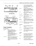
hard disk
WEED) light access light
power
\_
\.
power
button
diskette
drive
.
1.
I
hard disk or diskette
drive bay
optlon card slots