1
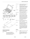
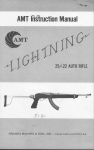
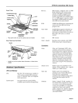
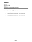
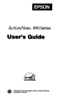
EPSON ActionNote 700 Series
Video RAM
512KB DRAM supports resolutions up to
1024 x 768 in 16 colors or 800 x 600 in 256
colors
Shadow RAM
Supports shadowing of system and video
BIOS ROM into RAM; selectable through
Clock/
calendar
Real-time clock, calendar, and CMOS
RAM; backed up by internal battery
Setup
Controllers
Video
trackball
hard disk drive
Video controller and video modes depend
on the LCD screen installed; 16-bit local
bus interface to the microprocessor;
hardware cursor and color expansion
features; internal timers for backlight
control and standby mode
Supports enhanced video modes on an
external monitor; maximum resolution of
800 x 600 x 256 colors or 1024 x 768 x 16
colors; automatic external monitor
detection; simultaneous display with LCD
screen using Fn F5 command or software
Diskette drive
Built-in super I/O controller for one
internal 3.5-inch diskette drive; supports
720KB and 1.44MB formats
Hard disk
Built-in super I/O controller has interface
to one 2.5-inch, IDE internal hard disk
drive
PCMCIA
Built-in Cirrus Logic CL-PD6710 controller
for PCMCIA version 2.1, Type II card slot;
supports Type I and Type II cards;
JEIDA 4.1 compatible; supports low power
and suspend modes; supports hot
insertion (including ExCA standards)
Computer Specifications
CPU and Memory
CPU
Cyrix 32-bit, 3.3 volt Cx486DX-V33
microprocessor; includes built-in math
coprocessor, 8KB of internal cache, and
APM and SMM power management
features; cache can be enabled or disabled
using Setup
System speed
Maximum speed (33 MHz) and low speed
(8 MHz) available; speed selection
through Setup
Memory
4MB RAM standard on the system board;
expandable to 8MB or 20MB using a 4MB
or 16MB memory expansion module
ROM
128KB Flash ROM device containing the
system and VGA BIOS, Setup program
code, and PCMCIA socket services;
upgradable through Setup using Flash
ROM upgrade diskette
Interfaces
4/94
External VGA
Auto-sensing, 15-pin, D-sub, female
connector for analog monitor; resolutions
of 640 x 480 (VGA), 800 x 600 x 256 colors
or 1024 x 768 x 16 colors
Parallel
Centronics compatible; 25-pin, D-sub,
female connector; standard 8-bit parallel;
supports standard (AT compatible),
bidirectional (PS/2 compatible), enhanced
(EPP), and high-speed (ECP) modes
Serial
RS-232C, programmable, asynchronous,
9-pin, D-sub male connector
Pointing device
or external
keyboard
Auto-sensing, 6-pin, mini-DIN connector
for a PS/2-type pointing device or
external keyboard
EPSON ActionNote 700 Series-l
EPSON ActionNote 700 Series
Phone jack
Fax/Modem
Characteristic
Compatibility
Command set
Data correction
Data compression
Dialing type
Keyboard
Trackball
Standard RJ-11 connector for the internal
fax/modem
Power Supply
AC adapter
Internal 9600/2400 baud send/receive
fax/modem with the following
characteristics:
Fax
Group 3, CCITT G3 V.2.1,
V.27ter, V.29 (send only)
9600, 7200, 4800, 2400,
300 baud
Class 1
MNP 2 to 4, V.42
MNP 5 V.42 bis
Touch-tone or pulse
Lightweight
Characteristic (standard)
AC connection two folding
connectors
6 feet (2 meters)
DC cable
Modem
Bell 103,212A, CCITT
V.22, V.22 bis
2400, 1200, 300 baud
Diskette drive
LCD Screen
Fast charge
cable: 6 feet
(2 meters)
6 feet (2 meters)
Enhanced AT
85 keys; 101-key keyboard compatible;
embedded numeric keypad and Fn key for
hot key commands; international
keyboard also available
DC-IN port
Built-in 16 mm, PS/2 compatible trackball
with two buttons
Battery pack
Rechargeable, internal, 2.3 Ah, 8.4 Volt
NiMH battery pack; current regulation by
thermistor; an internal bridge battery
allows the computer to run while the
battery pack is being changed
Auto adapter
The auto adapter allows the computer to
be powered and charged from the
cigarette lighter connector in an
automobile
Maximum current
Minimum current
Voltage
Mass Storage
Hard disk drive
There are two AC adapters: a lightweight
adapter supplied as standard, and a
larger, fast-charge adapter available as an
option.
One internal IDE hard disk drive, 2.5-inch
form factor; maximum height .5 inches
(12.7 mm); MCC mounting holes on the
base; Setup automatically detects drive
type
One internal, 3.5-inch diskette drive;
720KB or 1 1.44MB format
2.7A
0.6A
15V
Monochrome: 9.5-inch diagonal, 64 gray
shades, 640 x 480, backlit
Dual-scan STN color: 9.5-inch diagonal,
640 x 480 x 256 colors, backlit
Active matrix TFT color: 8.5-inch diagonal,
640 x 480 x 256 colors, backlit
Setup Program Stored in ROM; accessible by pressing F12
Caution
Use only the adapters and batteries designed for use with
the ActionNote 700 (AC adapter model numbers A881291
and A881301, Auto adapter model number A881311, and
battery pack A881281).
at system startup; includes power
management utilities
Software
Latest versions of MS-DOS, Microsoft
Windows, Comit for Windows modem
software, and WinFax Lite; PCMCIA
services and utilities; cursor enhancer;
on-line documentation; video drivers and
utilities for Microsoft Windows, Windows
Battery Monitor, and several MS-DOS
video utilities; all installed on the hard
disk drive
EPSON ActionNote 700 Series-2
Environmental Requirements
4/94
EPSON ActionNote 700 Series
Physical Dimensions
Adding Memory
The ActionNote 700 Series comes with 4MB of memory on
the system board. You can increase the memory to 8MB by
installing a 4MB memory module, or to 20MB by installing a
16MB memory module.
To install the memory module, press the keyboard forward
and lift the front of the keyboard until it tilts back to rest
against the LCD screen.
LEDs
+
Power-Green = power is on;
Yellow = battery is low;
Red = battery is very low, save data;
Red blinking = system is in Suspend mode
8
Hard disk drive-Computer is accessing the hard disk
drive
lr
Num Lock-Num Lock is on, which activates the
embedded numeric keypad
f3
Scroll Lock-Scroll Lock is on
Locate the three sockets near the center front of the board.
Align the three connectors on the memory module with the
three sockets on the system board; then press it firmly into
place.
sockets
Aa Caps Lock-Caps Lock is on
a
DC-IN-Yellow = power is supplied by the adapter
and the battery is charging;
Green = battery is fully charged;
Red = battery is too hot or too cold;
Blinking red = battery is installed incorrectly
or is damaged.
Replace the keyboard; then run Setup to make sure the
computer recognizes the new amount of memory.
System Board Major Components
Accessories
Ll Lightweight AC adapter
The following table lists the major components on the system
board.
Ll Carrying case
System board major components
Optional Equipment
0 4MB memory expansion module
Cl 16MB memory expansion module
Cl External keyboard
Cl External numeric keypad
Cl Additional NiMH battery packs
Cl Extra AC adapter
0 Enhanced, fast-charging AC adapter
Cl Adapter for an automobile cigarette lighter
Cl PCMCIA Type II cards including modems, flash RAM,
RAM, fax/modems, LAN cards, etc.
tl 260MB and higher capacity hard disk drive upgrades
When traveling by airplane, take the computer into the
4/94
EPSON ActionNote 700 Series-3
EPSON ActionNote 700 Series
Main System Board Diagrams
EPSON ActionNote 700 Series-4
EPSON ActionNote 700 Series
4/94
EPSON ActionNote 700 Series-5
EPSON ActionNote 700 Series
LED Connector
Connector Pin Assignments
LED connector pin assignments (J21)
Parallel port connector pin assignments (J8)
Pin 1 Signal
[ BAT_COM
1
Hard disk drive LED
2
3
Num Lock
4
Scroll Lock
5
caps Lock
1 Pin
6
7
8
9
I
1 Signal
+3V
AC_COM
LOW_BTTY
VL_BTTY
Diskette Drive Cable Connector
Diskette drive connector pin assignments (J18)
‘Active low logic
Serial port connector pin assignments (P2)
External keyboard/mouse connector pin assignments (J12)
Pin
1
2
3
Signal
Keyboard Data
Pointing device data
Ground
Pin
4
5
6
Signal
+5 VDC (fused)
clock, keyboard
Clock, pointing device
113
ISTEP
IDE Hard Disk Drive Connector
Video port connector pin assignments (PI)
Hard disk drive connector pin assignments (J11)
Internal Keyboard Connectors
Internal keyboard connector pin assignments (J14)
Pin
1-8
Signal
KINO-KIN7
Hard disk drive connector pin assignments (J10)
Internal keyboard connector pin assignments (J15)
Pin
1-16
[ Pin
1
2
3
4
5
6
7
8
9
10
1 Signal
1 KINO-KIN15
DC-IN Power Connector
DC-IN power connector pin assignments (J4)
Pin
1
2
3
Signal
DC input
Chassis ground
Chassis ground
EPSON ActionNote 700 Series-6
4/94
I Signal
1 IDERST_
I Ground
HDUD7
HDUD8
HDUD6
HDUD9
HDUD5
HDUD10
HDUD4
HDUD11
I Pin
1 11
1 12
13
14
15
16
17
18
19
20
I Signal
1 IHDUD3
1 HDUD12
HDUD2
HDUD13
HDUD1
HDUD14
HDUD0
HDUD15
Ground
Ground
EPSON ActionNote 700 Series
Fax/Modem Connector
DMA Assignments
Fax/Modem connector pin assignments (J20)
Pin
1
2
3
Signal
No connect
No connect
RING
Pin
4
5
6
Level
DMA0
DMA1
DMA2
DMA3
DMA4
DMA5
DMA6
DMA7
Signal
TIP
No connect
No connect
PCMCIA Connector
PCMCIA connector pin assignments (J9)
Assigned device
Available
Available
FDD controller
ECP
Cascade for CTRL 1
Available
Available
Available
Hardware Interrupts
IRQ no.
IRQ0
IRQ1
IRQ2
IRQ3
IRQ4
IRQ5
IRQ6
IRQ7
IRQ8
IRQ9
IRQ10
IRQ11
IRQ12
IRQ13
lRQ14
IRQ15
Function
Timer
Keyboard
Cascade
COM 2 (2F8h)
COM 1 (3F8h)
Available
FDD controller
Parallel port (LPT1)
Clock/calendar
cascade video
Available
AvailabIe
Trackball
Reserved for coprocessor
HDD controller
Available
System l/O Address Map
LCD Panel Connector
LCD connector pin assignments (J1)
LCD connector pin assignments (J2)
Pin
1-8
9
10
11
12
Signal
UD0-UD7
MOD
DEFP ground
FP ground
4/94
EPSON ActionNote 700 Series-7
EPSON ActionNote 700 Series
Diskette Drive Information
Standard diskette drive specifications
Information Reference List
Engineering Change Notices
None.
Technical Information Bulletins
None.
Product Support Bulletins
None.
Related Documentation
TM-AN700
EPSON ActionNote 700 Series Service Manual
PL-AN700
EPSON ActionNote 700 Series Parts Price List
400290700
EPSON ActionNote 700 Series User’s Guide
EPSON ActionNote 700 Series-8
4/94