1
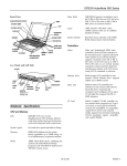
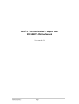
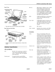
EPSON ActionNote 650
System speed
Maximum speed (50 MHz) and low speed
(12 MHz) available; speed selection
through keyboard commands
Memory
4MB RAM standard on the system board;
expandable to 8MB, 12MB, or 20MB using
a 4MB, 8MB, or 16MB memory module
ROM
128KB Flash ROM device containing the
system and VGA BIOS and System
Configuration utility (SCU) code
Video RAM
512KE DRAM supports resolutions up to
640 x 480 in 256 colors on the color LCD
and up to 1024 x 768 in 16 or 800 x 600 in
256 colors on an external monitor
Shadow RAM
Supports shadowing of 128KB of system
and video BIOS ROM into RAM
Clock /
calendar
Real-time clock, calendar, and CMOS
RAM; backed up by internal battery
Video
Chips and Technology® 32-bit local bus
interface to the microprocessor; supports
enhanced video modes on an external
monitor; supports resolutions up to 640 x
480 in 256 colors on the color LCD and up
to 1024 x 768 in 16 or 800 x 600 in 256
colors on an external monitor; display
mode selectable using the SCU or
Fn F12 command
Diskette drive
Built-in super I/O controller for one
internal 3.5-inch diskette drive; supports
720KB and 1.44MB formats
Hard disk
Built-in super I/O controller has interface
to one 2.5-inch long, 12.5 mm high IDE
internal hard disk drive; drive
compartment can accommodate drives up
to 19 mm high by removing spacer
PCMCIA
Built-in controller for PCMCIA version
2.1, Type I, II, or III cards; supports up to
two stacked Type I and Type II cards or
one Type III card; JEIDA 4.1 compatible;
supports standby and suspend modes;
supports hot insertion (including ExCA
standards)
Interfaces
Notebook Specifications
CPU and Memory
CPU
Cyrix SL-enhanced Cx486DX2-50
microprocessor; includes built-in math
coprocessor, 8KB of internal cache, and
power management features; cache can be
enabled or disabled using the SCU
10/25/94
External VGA
15-pin, D-sub, female connector for analog
monitor
Parallel
Centronics® compatible; 25-pin, D-sub,
female connector; supports normal (S-bit
AT compatible, unidirectional) and
bidirectional (16-bit PS/2 compatible)
modes
AN650-1
EPSON ActionNote 650
Serial
RS-232C, programmable, asynchronous,
9-pin, D-sub male connector
External
keyboard /
mouse
Auto-sensing, 6-pin, mini-DIN connector
for a PS/2-type external keyboard,
keypad, mouse, or other pointing device
Keyboard
85 / 86 keys; 101/102-key keyboard
compatible; embedded keypad; support
for hot key commands
Trackball
LCD Indicator The ActionNote 650 has the indicators
shown in the table below
Panel
Built-in 16 mm, PS/2 compatible trackball
with two buttons
Mass Storage
Hard disk drive
Meaning
Icon
One internal 2.5 inch long by .5 to .75 inch
(12.5 mm to 19 mm) high IDE hard disk
drive; SCU automatically detects standard
IDE drive types
Caps Lock
Caps Lock is on.
Num Lock
Num Lock is on.
Scroll Lock
Scroll Lock is on.
Keypad Lock
The embedded keypad
is locked.
Hard Disk
Activity
The computer is
accessing the hard disk
drive.
Diskette Drive
Activity
The computer is
accessing the diskette
drive.
PCMCIA
Card Activity
The computer is
accessing a PCMCIA
card.
The following table shows the
characteristics for the Toshiba
MK1724FCV drive.
Capacity
262MB
Heads
16
Cylinders
842
Diskette drive
1 Sectors
38
One internal, 3.5-inch, low power
consumption, diskette drive; 720KB or
1.44MB format
Stored in ROM; accessible by pressing
Ctrl Alt S at system startup or at MS-DOS
prompt; includes power management
features
Software
Latest versions of MS-DOS and Microsoft
Windows; Borland SideKick for Windows;
ClarisWorks for Windows; trial versions of
CompuServe WinCIM, America Online,
and OAG FlightDisk; PCMCIA services,
drivers, and utilities; on-line Windows
and other manuals; video drivers and
utilities for Microsoft Windows; power
management utilities; all installed on the
hard disk drive
Shows battery charge
status by displaying
from zero to four vertical
bars inside the battery
symbol.
Battery
Charging
The AC adapter is
charging the battery.
AC Power
The computer is running
on AC power rather
than the battery.
Power Sources
AC adapter
Battery
Monochrome: 9.5-inch diagonal, 64 gray
shades, 640 x 480, backlit
Dual-scan STN color: 10.3-inch diagonal,
640 x 480 x 256 colors, backlit
AN650-2
Battery Status
I
System
Configuration
Utility
LCD Screen
The system is in
suspend mode
Rechargeable, 12 Volt, 2.6Ah NiMH
battery; current regulation and automatic
charge stop by thermistor
Caution
Use only the adapters and replacement batteries designed
for use with the ActionNote 650 series (AC adapter model
number TSA3 and battery model number 10HR-4/3AU).
10/25/94
EPSON ActionNote 650
Power
Management
You can access the power management
features through Setup or by pressing Ctrl
Alt P in text mode or Fn Esc in graphics
mode.
Power Management Options in Setup
Option
Power savings
Alarm resume
Description
Always*, Battery,
Physical Dimensions
Always = power management active
Disable
Battery = active only from battery.
Suspend*, Warn
Suspend puts computer into suspend mode
Only
when battery charge IS low.
Disable*, Enable
Enable lets you set a time after which he
Model
Monochrome
STN color
going into Suspend mode.
4*, 8, 6, Disable
Global standby
1, 2, 4, 8, 12, 16,
Sets timeout in minutes before computer
Disable
slows CPU and turns off all devices.
Sets timeout in seconds before computer
Sets timeout in minutes before computer
enters Suspend mode.
Disk suspend
Disable*, Enable
Enables Suspend of the hard drive
Video monitoring
Disable*, Enable
“Enable” causes any screen activity (e.g., a
8.6
8.6
219
219
11
11
44.5
51
5.8
6.8
u Additional NiMH batteries
entering Standby or Suspend mode.
u External battery charger
u Auto adapter
1, 2, 4, 8, 12, 16,
Sets timeout in minutes for screen inactivity
Always on
before he LCD backlight IS turned off.
1,
Sets timeout in minutes for HDD inactivity
u Extra AC adapter
before drive IS turned off.
u PCMCIA Type II cards including Flash RAM, SRAM,
modem, fax/modem, and LAN cards, etc.
Built in Power Management Options
Connector Pin Assignments
Mode
Entry
Description
Exit
CPU
When system IS inactive
Reduces CPU clock speed
When CPU IS required, full
standby
279 1.75
279 2.0
u External numeric keypad
flashing cursor) to prevent the system
8, 12, 16,
Weight
u External keyboard
1, 5, 10*, 20, 30, 40,
Always on
Height
u 4MB, 8MB, and 16MB memory expansion modules
60, Disable
Hard disk
Width
Optional Equipment
slows CPU.
Auto suspend
Depth
inches mm inches mm inches mm lb
computer will resume full operation after
CPU standby
Caution
When traveling by airplane, take the computer into the
passenger compartment as carry-on luggage to prevent it
from being stored in an unpressurized storage
compartment.
LCD Connector 2 (JP201)
performance returns
Global
When system IS inactive for
Reduces CPU speed
If there IS activity
Standby
timeout period set for Global
further; turns off LCD
keyboard or pointing
Standby
backlight; puts HDD and
device, resumes full
other components in
performance in a few
low-power state.
seconds.
When system IS inactive for
CPU clock stopped; LCD
If the Suspend/Resume
timeout period set for
and HDD turned off; other
button IS pressed the
Suspend, or Suspend/
components suspended.
system resumes.
Pin No.
1
Signal
Pin No.
Signal
Pin No.
Signal
1
LCDVDD
6
P11
11
DE
2
GND
7
P12
12
GND
3
1
P8
1 P10
1
8
1 10
1
P13
1 P15
1
13
1 15
1
GND
1 GND
LCD Connector 1 (JP202)
Resume IS pressed, or battery
IS low.
Suspend to
When system IS inactive for
Saves contents of system
Press power on to start
disk
timeout period set for
and video memory to a file
system Full performance
Suspend, or Suspend/
on disk; then turns system
Resume IS pressed, or battery
off completely
30 seconds.
IS low.
Environmental Requirements
Line In Connector (JP203)
10/25 94
AN650-3
1
EPSON ActionNote 650
External Keyboard/Mouse Connector (JP204)
Internal Keyboard Connector (JP209)
Trackball/ Speaker Connector (JP205)
VGA Connector for an External Monitor (JP206)
Serial Port Connector (JP211)
On/ Off Button Connector (JP213)
Status LCD Display Board Connector (JP207)
Battery Connector (JP215)
Parallel Port Connector (JP208)
Phone Jack (JP218)
AN650-4
10/25/94
EPSON ActionNote 650
PCMCIA Socket B Connector (JP219)
Memory Connector 1 (JP221)
Memory Connector 2
Signal
MA5
t
L
L
L
L
L
c
L
MA6
MA7
MA8
MA9
DRAMWE
DRAMWE
FDD Connector (JP223)
10/25/94
AN650-5
EPSON ActionNote 650
CPU Selection Connector (JP224)
1 Pin No.
Pin No.
3
Signal
CURR:
2.1A/1.05A
current
source
Inverter Connector (P2)
System I/O Addresses, DMA Assignments, and
Hardware Interrupts
I/O Addresses
Hex
Address
PCMCIA Socket A Connector (JP225)
Device
Hex
Address
Device
Hex
Address
Device
DMA controller 1
0F0-0F1
Clear
math coprocessor
busv
27F-2F8
Reserved
020-040
Interrupt
controller
0F1-0F8
Reset
math coprocessor
2F8-2FF
Serial
port 2
040-060
Timer/
counter
Math coprocessor
2FF-3B0
Keyboard
controller
100-1F0
Reserved
3B0-3F0
Video
system
RTC NMI
1F0-200
Hard disk
drive
3BC-3BE
3
Parallel
port 1
DMA
page
register
200-208
Game port
3F0-3F8
Diskette
drive
controller
0A0-0C0
Interrupt
controller
2
208-278
Reserved
3F8-3FF
Serial
port 1
0C0-0F0
DMA controller 2
240-24F
PCMCIA
controller
070-080
DMA Assignments
Level
Device
Level
Device
Level
Device
DMA0
Available
DMA3
ECP
DMA6
Available
DMA1
Available
DMA4
Cascade for
Ctrl 1
DMA7
Available
Diskette
Controller
AN650-6
10l25l94
Available
EPSON ActionNote 650
Hardware Interrupts
Related Documents
Engineering Change Notices
None.
Technical Information Bulletins
None.
Product Support Bulletins
None.
Related Documentation
400387400
EPSON ActionNote 600 Series User’s Guide
400390500
For Software Support
PL-AN650
EPSON ActionNote 650 Parts Price List
TM-AN650T
EPSONActionNote 600 Series Service Manual
10l25l94
AN650-7