1
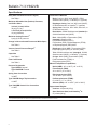
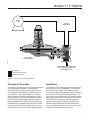
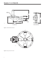
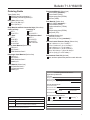
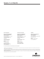
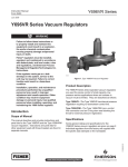
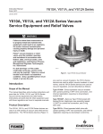
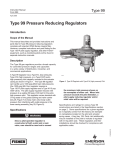
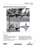
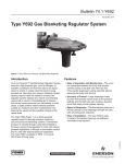
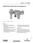
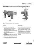
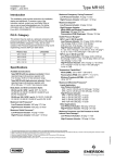
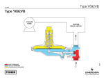
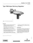
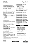
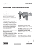
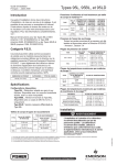
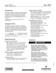
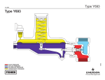
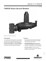
Bulletin 71.3:Y692VB
June 2009
Y692VB Series Vacuum Breaker
W7429
Figure 1. Type Y692VB Vacuum Breaker
Introduction
Features
The Y692VB Series direct-operated vacuum breakers
are used for the precise control of small capacity and
low-pressure service applications where an increase
in vacuum must be limited. The Type Y692VB has
internal pressure registration. The Type Y692VBM has
a control line connection and an O-ring stem seal to
block the throat for external pressure registration.
• Precision Control of Low-Pressure Settings—
Large diaphragm area provides more accurate
control at low-pressure settings.
• Installation Adaptability—Four-position vent
mounting and 360° adjustability of the union nut
connection permit flexibility in vent positioning and
installation in awkward positions or limited spaces.
D102663X012
• Corrosion Resistance—Constructions are
available in a variety of materials for compatibility
with corrosive process gases.
www.emersonprocess.com/regulators
Bulletin 71.3:Y692VB
Specifications
Body Sizes and End Connection Styles(1)
Construction Materials
Body: Cast iron, WCC steel (NACE), CF8M
Stainless steel (NACE), or Hastelloy® C (optional)
Diaphragm Casing: Cast iron, WCC steel (NACE), CF8M Stainless steel, or Hastelloy® C (optional)
Spring Case: Cast iron, WCC steel, Aluminum, or CF8M Stainless steel
Disk Holder: S30200 Stainless steel (standard) or
S31600 Stainless steel (NACE)
Disk: Nitrile (NBR) or Fluorocarbon (FKM) (standard), Neoprene (CR),
Polytetrafluoroethylene (PTFE),
Fluorocarbon (FKM), Perfluoroelastomer (FFKM),
or Ethylenepropylene (EPR) NACE
Diaphragm: Nitrile (NBR), Fluorocarbon (FKM), Ethylenepropylene (EPR), or Silicone (VMQ)
Trim: S30200 stainless steel (standard), S31600
Stainless steel (NACE), or Hastelloy® C (optional)
O-rings: Nitrile (NBR), Fluorocarbon (FKM), Perfluoroelastomer (FFKM), or
Ethylenepropylene (EPR)
See Table 1
Maximum Allowable Inlet (Positive) Pressure(2)
and Orifice Sizes
3/4-inch (19 mm) Orifice:
30 psig (2,1 bar)
1-3/16-inch (30 mm) Orifice:
13 psig (0,89 bar)
Maximum Casing Pressure(2)
8 psig (0,55 bar) vacuum
Change in Vacuum Control Pressure to Wide-Open(2)
See Table 2
Vacuum Control Pressure Ranges(2)
See Table 2
Capacities
See Table 5
Flow Coefficients
See Table 3
Pressure Registration
Type Y692VB: Internal
Type Y692VBM: External
Spring Case Connection
3/4 NPT
Type Y692VB Gauge Tap Connection
1/4 NPT
Type Y692VBM Control Line Connection
1/2 NPT
Material Temperature Capabilities(2)
Nitrile (NBR): -40° to 180°F (-40° to 82°C)
Fluorocarbon (FKM):
40° to 300°F (4° to 149°C)
Ethylenepropylene (EPR):
-20° to 200°F (-29° to 93°C)
Perfluoroelastomer (FFKM):
0° to 300°F (-17° to 149°C)
Silicone (VMQ): -40° to 400°F (-40° to 204°C)
Approximate Weights
Cast Iron: 45 pounds (20 kg)
Steel, Stainless Steel, and Hastelloy® C:
57 pounds (26 kg)
1. End connections for other than U.S. standards can usually be provided; consult the local Sales Office.
2. The pressure/temperature limits in this bulletin and any applicable standard or code limitation should not be exceeded.
2
Bulletin 71.3:Y692VB
Type Y692VB
Type Y69
VACUUM
VACUUM
PUMP
PUMP
VACUUM
VACUUM
BEINGLIMITED
LIMITED
BEING
VACUUM
PUMP
VACUUM
BEING LIMITED
TYPE Y692VB
VACUUM BREAKER
INLET PRESSURE
CONTROL PRESSURE (VACUUM)
ATMOSPHERIC PRESSURE
B2579
INLET PRESSURE
INLET
PRESSURE
CONTROL PRESSURE
(VACUUM)
CONTROL
PRESSURE
(VACUUM)
ATMOSPHERIC PRESSURE
ATMOSPHERIC
PRESSURE
POSITIVE PRESSURE, ATMOSPHERE,
OR A LESSER VACUUM THAN THE
VACUUM BEING LIMITED
B2579
Figure 2. Type Y692VB Operational Schematic
Principle of Operation
Installation
An increase in vacuum (decrease in absolute pressure)
beyond the setpoint registers on the diaphragm,
opening the disk. This permits body inlet pressure to
enter the system and restore the controlled vacuum
to the setpoint. On the Type Y692VB, the pressure
at the regulator body outlet registers directly into the
diaphragm casing. The Type Y692VBM has a control
line connecting the diaphragm casing to the vacuum
being controlled and an O-ring stem seal blocking the
throat allowing for registration only through the control
line connection (outlet body pressure may or may not
be the same as the pressure in the diaphragm casing).
The versatility of the Y692VB Series vacuum breakers
permits a wide variety of installations. The body may
be mounted in any position (360° rotation possible)
relative to the spring and diaphragm cases by loosening
the union nut and rotating the diaphragm casing. The
spring case can be rotated to fit the orientation required.
Any mounting position provides excellent performance.
When exposed to the weather, the spring case port
should be protected by an optional umbrella vent or
should be pointed downward to allow condensate to
drain. On indoor installations, this port should be piped
outdoors if used in hazardous gas service.
3
Bulletin 71.3:Y692VB
Table 1. Body Sizes and End Connection Styles
CONSTRUCTION MATERIAL AND END CONNECTION STYLE(1)
BODY SIZE,
NPS (DN)
Cast Iron
Steel or Stainless Steel
Hastelloy® C
1-1/2 (40)
NPT
2 (50)
NPT or CL125 FF
NPT, SWE, CL150 RF,
CL300 RF, or PN 16/25/40
NPT or CL150 RF
1. All flanges are welded on to the body and have a face-to-face dimension of 14-inches (356 mm).
Table 2. Vacuum Control Pressure Ranges and Spring Part Numbers
Vacuum CONTROL
PRESSURE RANGE(1)
change in vacuum control pressure to reach wide-open
SPRING Part NUMBEr
SPRING
COLOR
SPRING Wire diameter
1 to 3-inches w.c.
1.5 to 5-inches w.c.
3 to 8-inches w.c.
(2 to 7 mbar)(2)
(4 to 12 mbar)(2)
(7 to 20 mbar)(2)
1.2-inches w.c.
2.2-inches w.c.
4.0-inches w.c.
(3 mbar)
(5 mbar)
(10 mbar)
1D892527022
1D7654000A2
0B0197000A2
Brown
Unpainted
Purple
0.109-inches
0.120-inches
0.148-inches
(2,77 mm)
(3,05 mm)
(3,76 mm)
8 to 16-inches w.c.
16 to 32-inches w.c.
0.25 to 3 psig
(20 to 40 mbar)
(40 to 80 mbar)
(17 to 207 mbar)
5.0-inches w.c.
10.5-inches w.c.
2 psig
(13 mbar)
(26 mbar)
(138 mbar)
1B766270622
1B883327022
1A630627022
Gray
Unpainted
Black
0.156-inches
0.187-inches
0.275-inches
(3,96 mm)
(4,75 mm)
(6,99 mm)
1. Pressure ranges are based on the spring case pointing up. Pointing the spring case down increases the pressure range 1.7-inches w.c. (4 mbar).
(Example: 1 to 3-inches w.c. (2 to 7 mbar) changes to 2.7 to 4.7-inches w.c. (7 to 12 mbar)).
2. Do not use Fluorocarbon (FKM) with these springs at diaphragm temperatures lower than 40°F (4°C).
Table 3. Flow Coefficients
ORIFICE SIZE, INCHES (mm)
3/4
1-3/16
(19)
(30)
WIDE-OPEN
Cg
WIDE-OPEN
Cv
C1
Km
260
720
7.4
20.6
35
35
0.79
Table 4. IEC Sizing Coefficients
4
XT
FD
FL
0.76
0.50
0.89
Bulletin 71.3:Y692VB
Table 5. Y692VB Series Capacities (based on atmospheric inlet pressure)
Vacuum CONTROL
PRESSURE RANGE
vacuum CONTROL
Pressure SETTING
1 to 3-inches w.c. (2 to 7 mbar)
1.5 to 5-inches w.c. (4 to 12 mbar)
3 to 8-inches w.c. (7 to 20 mbar)
8 to 16-inches w.c. (20 to 40 mbar)
16 to 32-inches w.c. (40 to 80 mbar)
0.25 to 3 psig (17 to 207 mbar)
Change in Vacuum
2-inches w.c. (5 mbar)
4-inches w.c. (10 mbar)
7-inches w.c. (17 mbar)
1-inch w.c. (2 mbar)
1-inch w.c. (2 mbar)
1-inch w.c. (2 mbar)
14-inches w.c. (35 mbar)
28-inches w.c. (70 mbar)
2 psig (138 mbar)
2-inches w.c. (5 mbar)
6-inches w.c. (15 mbar)
0.4 psig (28 mbar)
Maximum Allowable Vacuum
pressure
8 psig
(0,55 bar)
CAPACITIES IN SCFH (Nm3/h) OF AIR
3/4-inch
(19 mm) Orifice
1-3/16-inch
(30 mm) Orifice
500 (13,4)
700 (18,8)
900 (24,1)
1000 (26,8)
1400 (37,5)
1800 (48,2)
900 (24,1)
1000 (26,8)
1300 (34,8)
1800 (48,2)
1900 (50,9)
2500 (67,0)
Conversion Factors
Note
Downstream piping will vary with the
installation, but to obtain the calculated
characteristics, the pipe should be the
same size as the outlet and should be
straight for the first 18-inches (460 mm).
Capacity Information
To determine equivalent capacities of 0.6 specific
gravity natural gas, propane, butane, or nitrogen,
multiply the calculated capacity by the following
appropriate conversion factor: 1.29 for 0.6 natural
gas, 0.810 for propane, 0.707 for butane, or 1.018 for
nitrogen. For gases of other specific gravities, divide
by the square root of the appropriate specific gravity.
To determine flow capacities for the Y692VB Series
vacuum breakers, use the following formula:
Ordering Information
Q
where,
= P1abs Cg sin
)
3415
P
C1
P1abs
)
When ordering, specify:
deg
Q = flow capacity in scfh (60°F, 14.7 psia) of air
P1abs= absolute inlet pressure, psia (P1 psig + 14.7)
Cg = flow coefficient (from Table 3)
C1 = 35 (from Table 3)
P = pressure drop across the vacuum breaker
If the actual change in control pressure (from the
service conditions) is less than the change in control
pressure required to reach wide-open (Table 2), the Cg
in the formula must be reduced accordingly. To obtain
the correct reduced Cg, multiply the Cg (Table 3) by the
ratio of the actual change in control pressure to the
change in control pressure to reach wide-open.
Application
1. Composition and specific gravity of gas (including
chemical analysis if possible)
2. Temperature range
3. Inlet pressures (maximum, minimum, nominal)
4. Pressure drops
5. Desired pressure setting or range
6. Flow rates (minimum, maximum, normal)
7. Piping size(s)
Construction
Refer to the Specifications section and to each
referenced table; specify the desired selection
whenever there is a choice to be made. Be sure to
specify spring case port location from Figure 4.
5
Bulletin 71.3:Y692VB
1/4 NPT
gauge Tap
9.68
(246)
5.88
(149)
14
(356)
2.94
(75)
10.38
(264)
W5930_1
INCHES
(mm)
17.44
(443)
NPT Dimensions
Flanged Dimensions
Figure 3. Y692VB Series Dimensions
F
C
E
CJ4598-B
D
Figure 4. Spring Case Port Location
6
Bulletin 71.3:Y692VB
Ordering Guide
Type (Select One)
Y692VB (internal registration)***
Y692VBM (external registration)***
Body Size (Select One)
NPS 1-1/2 (DN 40)***
NPS 2 (DN 50)***
Body Material and End Connection Style (Select One)
Hastelloy® C
Cast Iron Body
NPT*
NPT***
CL150 RF***
CL125 FF***
WCC Steel
NPT***
CL150 RF**
CL300 RF**
PN 16/25/40*
CF8M Stainless Steel
NPT***
CL150 RF**
CL300 RF**
PN 16/25/40*
Spring Case Material (Select One)
Cast Iron***
WCC Steel***
CF8M Stainless Steel**
Diaphragm Case Material (Select One)
Cast Iron***
WCC Steel***
CF8M Stainless Steel**
Hastelloy® C*
Diaphragm Material (Select One)
Nitrile (NBR) (standard)***
Fluorocarbon (FKM)**
Ethylenepropylene (EPDM)*
Silicone (VMQ)*
Disk Material (Select One)
Nitrile (NBR) (standard)***
Fluorocarbon (FKM)**
Perfluoroelastomer (FFKM)*
PTFE*
Ethylenepropylene (EPDM)*
Neoprene (CR)*
Orifice Size (Select One)
3/4-inch (19 mm)***
1-3/16-inch (30 mm) (standard)***
Vacuum Control Pressure Range (Select One)
1 to 3-inches w.c. (2 to 7 mbar)***
1.5 to 5-inches w.c. (4 to 12 mbar)***
3 to 8-inches w.c. (7 to 20 mbar)***
8 to 16-inches w.c. (20 to 40 mbar)***
16 to 32-inches w.c. (40 to 80 mbar)***
0.25 to 3 psig (17 to 207 mbar)***
Replacement Parts Kit (Optional)
Yes, send one replacement parts kit to match this order.
Trim Material (Select One)
302 Stainless Steel***
316 Stainless Steel**
Hastelloy® C*
Vacuum Specification Worksheet
Application Specifications:
Tank Size
Pump In Rate
Pump Out Rate
Blanketing Gas (Type and Specific Gravity)
Regulators Quick Order Guide
***
**
*
Readily Available for Shipment
Allow Additional Time for Shipment
Pressure Requirements:
Upstream Pressure
Downstream Pressure
Control Pressure:
Upstream
Downstream
Maximum Flow
Special Material Requirements:
Iron Steel Stainless Steel Hastelloy® C
Other
Other Requirements: Special Order, Constructed from Non-Stocked Parts.
Consult Your local Sales Office for Availability.
Availability of the product being ordered is determined by the component with the
longest shipping time for the requested construction.
7
Bulletin 71.3:Y692VB
Industrial Regulators
Natural Gas Technologies
TESCOM
Emerson Process Management
Regulator Technologies, Inc.
Emerson Process Management
Regulator Technologies, Inc.
Emerson Process Management
Tescom Corporation
USA - Headquarters
McKinney, Texas 75069-1872 USA
Tel: 1-800-558-5853
Outside U.S. 1-972-548-3574
USA - Headquarters
McKinney, Texas 75069-1872 USA
Tel: 1-800-558-5853
Outside U.S. 1-972-548-3574
USA - Headquarters
Elk River, Minnesota 55330-2445 USA
Tel: 1-763-241-3238
Asia-Pacific
Shanghai, China 201206
Tel: +86 21 2892 9000
Asia-Pacific
Singapore, Singapore 128461
Tel: +65 6777 8211
Europe
Bologna, Italy 40013
Tel: +39 051 4190611
Europe
Bologna, Italy 40013
Tel: +39 051 4190611
Gallardon, France 28320
Tel: +33 (0)2 37 33 47 00
Middle East and Africa
Dubai, United Arab Emirates
Tel: +971 4811 8100
Europe
Selmsdorf, Germany 23923
Tel: +49 (0) 38823 31 0
For further information visit www.emersonprocess.com/regulators
The Emerson logo is a trademark and service mark of Emerson Electric Co. All other marks are the property of their prospective owners. Fisher is a mark owned by Fisher Controls, Inc., a
business of Emerson Process Management.
The contents of this publication are presented for informational purposes only, and while every effort has been made to ensure their accuracy, they are not to be construed as warranties or
guarantees, express or implied, regarding the products or services described herein or their use or applicability. We reserve the right to modify or improve the designs or specifications of such
products at any time without notice.
Emerson Process Management does not assume responsibility for the selection, use or maintenance of any product. Responsibility for proper selection, use and maintenance of any Emerson
Process Management product remains solely with the purchaser.
©Emerson Process Management Regulator Technologies, Inc., 1999, 2009; All Rights Reserved