1
Bulletin 74.1:Y692
November 2014
Type Y692 Gas Blanketing Regulator System
W5930-1
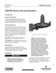
Figure 1. Type Y692 Low-Pressure Gas Blanketing Regulator
Introduction
Features
An Accu-Pressure™ Gas Blanketing Regulator System
reduces a high-pressure gas, such as Nitrogen, to
maintain a protective environment above any liquid
stored in a tank or vessel when the liquid is being
pumped out. Also when the vessel is suddenly cooled,
causing vapors inside the vessel to contract, the
regulator system replaces the volume of contracting
vapors with a volume of blanketing gas to prevent
the internal vessel pressure from decreasing. In both
cases, a slight positive vessel pressure prevents
outside air, moisture and other contaminants from
entering the vessel and the possible collapse of the
vessel walls.
• Accuracy of Control—Large diaphragm areas
provide more precise control even at low-pressure
settings and the pitot tube also creates a dynamic
boost that helps provide greater capacity.
• Speed of Response—The downstream pressure is
sensed directly by the diaphragm through the pitot
tube providing quick response.
• Ease of Installation—The Type Y692 is easy
to install in the pipeline because no additional
connections are required.
D102032X012
The Type Y692 (Figure 1) is a direct-operated
regulator used for accurate pressure control on
very low-pressure blanketing systems. Downstream
pressure is sensed through a pitot tube installed in
the lower casing of the regulator for units with internal
pressure registration or through a downstream control
line for units with external pressure registration.
The Type Y692 is available in NPS 1-1/2 and 2 /
DN 40 and 50 body sizes.
• Ease of Inspection and Maintenance—The union
nut connection between the body and actuator
permits access to the disk and orifice by only
removing the diaphragm casing assembly without
removing the body from the line.
www.fisherregulators.com
Bulletin 74.1:Y692
Specifications
This section lists the specifications of theType Y692 Gas Blanketing Regulator System. Factory specification,
such as spring range and orifice size are stamped on the nameplate fastened on the regulator at the factory.
Available Configurations
Direct-operated pressure reducing regulator with
external or internal pressure registration with
seven outlet (control) pressure ranges from
1 in. w.c. to 7 psig / 2 mbar to 0.48 bar. Available in
NPS 1-1/2 and 2 / DN 40 and 50 body sizes.
Body Sizes and End Connection Styles(1)
Cast Iron: NPS 1-1/2 / DN 40, NPT,
NPS 2 / DN 50, NPT or CL125 FF
Steel: NPS 1-1/2 or 2 / DN 40 or 50, NPT, SWE,
CL150 RF, CL300 RF or PN 16/25/40
Stainless steel: NPS 1-1/2 or 2 / DN 40 or 50,
NPT, CL150 RF, CL300 RF or PN 16/25/40
Maximum Inlet Pressure(2)
150 psig / 10.3 bar
Maximum Outlet (Casing) Pressure(2)
15 psig / 1.0 bar
Maximum Operating Outlet (Control) Pressure to
Avoid Internal Part Damage(2)
3 psig / 0.21 bar above outlet (control)
pressure setting
Control Pressure Ranges(2)
See Table 1
Flow Capacities
See Table 5
Relief Sizing Coefficients
See Table 6
Orifice Size
See Table 6
Pressure Registration
Internal (standard) or External
Spring Case Connection
1/4 NPT
Temperature Capabilities(2)
Nitrile (NBR):
-20 to 180°F / -29 to 82°C
Fluorocarbon (FKM):
0 to 300°F / -18 to 149°C
Perfluoroelastomer (FFKM):
-20 to 300°F / -29 to 149°C
EthylenePropylene (EPDM):
-20 to 275°F / -29 to 135°C
IEC Sizing Coefficients
XT: 0.775
FD: 0.50
FL: 0.89
Approximate Weights
Cast Iron Body: 45 lbs / 20 kg
Steel/Stainless steel Body: 57 lbs / 26 kg
Canadian Registration Number (CRN)
Approved
PED (Pressure Equipment Directive) Category
The Type Y692 may be used as a safety
accessory with pressure equipment in the
PED 97/23/EC Category I.
Construction Materials
Body, Union Nut, Spring Case and Lower
Casing Assembly: Cast iron, WCC steel,
CF8M Stainless steel
Control Spring, Control Spring Seat, Split Ring
and Diaphragm Plate: Plated steel
Diaphragm: Nitrile (NBR) (standard),
Fluorocarbon (FKM), Ethylenepropylene (EPDM),
Silicone (VMQ)
O-rings: Nitrile (NBR), Fluorocarbon (FKM),
Perfluoroelastomer (FFKM),
Ethylenepropylene (EPDM)
Orifice, Pusher Post, Pusher Post Connector,
Lever Assembly, Stem and Pitot Tube:
Stainless steel
Gasket: Composition
Disk Assembly: Nitrile (NBR) and Stainless steel,
Fluorocarbon (FKM) and Stainless steel,
Polytetrafluoroethylene (PTFE) and Stainless steel
or Ethylenepropylene (EPDM) and Stainless steel
1. Fabricated by using slip-on flanges and socket welding nipples into body.
2. The pressure/temperature limits in this Bulletin and any applicable standard limitation should not be exceeded.
2
Bulletin 74.1:Y692
Table 1. Control Pressure Ranges
CONTROL PRESSURE RANGE WITH
CASE BARREL POINTED DOWN
Light Spring
Assembly
Heavy spring
Assembly
1 to 3 in. w.c. / 2 to 7 mbar(2)(3)
3 to 11 in. w.c. / 7 to 27 mbar(2)(4)
6.5 in. w.c. to 1.2 psig / 16 mbar to 83 mbar(5)
0.7 to 2 psig / 48 mbar to 0.14 bar
1 to 3.2 psig / 69 mbar to 0.22 bar
2 to 5.5 psig / 0.14 to 0.38 bar
4 to 10 psig / 0.28 to 0.69 bar
CONTROL SPRING
COLOR CODE
CONTROL SPRING
PART NUMBER
Brown
Iridite
Green
Blue
Orange
Silver with green stripe
Silver
1D892527022
0B019727052
0B019427052
0B019627032
0A081127202
0Y066427022
1H802427032
SPRING WIRE
DIAMETER
In.
mm
0.109
2.77
0.148
3.76
0.187
4.75
0.225
5.71
0.250
6.35
0.363
9.22
0.406
10.3
SPRING FREE
LENGTH
In.
mm
6.12
155
6.00
152
6.00
152
6.00
152
6.00
152
6.00
152
6.00
152
1. Install with spring case pointing down to achieve low setpoints in these spring ranges.
2. Do not use Fluorocarbon (FKM) diaphragm with these springs at diaphragm temperature lower than 60°F / 16°C.
3. Installation with spring case pointing up will change outlet (control) pressure range to 3 to 5 in. w.c. / 7 to 12 mbar.
4. Installation with spring case pointing up will change outlet (control) pressure range to 5.75 to 14 in. w.c. / 14 to 35 mbar.
5. Installation with spring case pointing up will change outlet (control) pressure range to 7.5 in. w.c. to 1.3 psig / 19 to 90 mbar.
Table 2. Flow Rate Conversion(1)
MULTIPLY MAXIMUM PUMP RATE OUT
BY
TO OBTAIN
U.S. GPM
U.S. GPH
m3/hr
Barrels/hr
Barrels/day
8.021
0.1337
1.01
5.615
0.2340
SCFH
SCFH
Nm3/H
SCFH
SCFH
1. Gas flow of blanketing gas to replace liquid pumped out.
Table 3. Conversion Factors (for converting Nitrogen flow rates to other gas flow rates)
BLANKET GAS
SPECIFIC GRAVITY
CORRECTION FACTOR
Natural Gas
0.60
1.270
Air
1.00
0.985
Dry CO2
1.52
0.797
Correction Factor =
0.985
SG
Table 4. Gas Flow Required for Thermal Heating (Outbreathing) or Cooling (Inbreathing) per API 2000 (Interpolate for Intermediate size)
VESSEL CAPACITY
AIR FLOW RATE REQUIRED
Barrel
Gallon
Liter
SCFH
Nm3/h
60
100
500
1000
2000
2500
4200
21,000
42,000
84,000
9500
16,000
79,500
159,000
318,000
60
100
500
1000
2000
1.6
2.7
1.3
26.8
53.6
3000
4000
5000
10,000
15,000
126,000
168,000
210,000
420,000
630,000
477,000
636,000
795,000
1,590,000
2,385,000
3000
4000
5000
10,000
15,000
80.4
107
134
268
402
20,000
25,000
30,000
35,000
40,000
840,000
1,050,000
1,260,000
1,470,000
1,680,000
3,180,000
3,975,000
4,769,000
5,564,000
6,359,000
20,000
24,000
28,000
31,000
34,000
536
643
750
831
911
45,000
50,000
60,000
70,000
80,000
1,890,000
2,100,000
2,520,000
2,940,000
3,360,000
7,154,000
7,949,000
9,539,000
11,129,000
12,718,000
37,000
40,000
44,000
48,000
52,000
992
1072
1179
1286
1394
90,000
100,000
120,000
140,000
160,000
3,780,000
4,200,000
5,040,000
5,880,000
6,720,000
14,308,000
15,898,000
19,078,000
22,437,000
25,437,000
56,000
60,000
68,000
75,000
82,000
1501
1608
1822
2010
2198
180,000
7,560,000
28,616,000
90,000
2412
3
Bulletin 74.1:Y692
Type Y692
Type Y692
VENT
VALVE
BLOCK
VALVE
SUPPLY
PRESSURE
VENT
VALVE
VENT
POINTED
DOWNWARD
BLOCK
VALVE
T
GAS BLANKETING PRESSURE
July 2007
Type Y692
INLET PRESSURE
OUTLET PRESSURE
ATMOSPHERIC PRESSURE
LIQUID
TYPE Y692 WITH INTERNAL REGISTRATION
Type Y692
VENT
VALVE
BLOCK
VALVE
INLET PRESSURE
CONTROL PRESSURE
SUPPLY (OUTLET PRESSURE)
PRESSURE
ATMOSPHERIC
PRESSURE
VENT
VALVE
VENT
POINTED
DOWNWARD
BLOCK
VALVE
GAS BLANKETING PRESSURE
LIQUID
TYPE Y692 WITH EXTERNAL REGISTRATION
A6340
INLET PRESSURE
CONTROL PRESSURE (OUTLET PRESSURE)
ATMOSPHERIC PRESSURE
INLET PRESSURE
PRESSURE
Figure OUTLET
2. Type Y692
Operational Schematics
ATMOSPHERIC PRESSURE
ONTROL PRESSURE (OUTLET PRESSURE)
LET PRESSURE
TMOSPHERIC PRESSURE
4
Bulletin 74.1:Y692
Principle of Operation
Installation
The Type Y692 Gas Blanketing Regulator reduces a
high-pressure gas to maintain a positive low-pressure
of blanket gas over a stored liquid when the liquid
is being pumped out of the vessel (see Figure 2).
Also when the vessel (or tank) is suddenly cooled,
causing vapors to contract, the regulator replaces
the volume of contracting vapors with a volume of
blanketing gas to prevent the internal vessel pressure
from decreasing. In both cases, a positive vessel
pressure prevents outside air from entering the vessel
and reduces the possibility of atmospheric pressure
collapsing the vessel.
Install the Type Y692 regulator with the spring case
barrel pointed down. This will assure that the lowest
set pressure shown in Table 1 is achieved. Flow
through the regulator body is indicated by the flow
arrow cast on the body. If a block valve is required,
install a full flow valve between the regulator and the
blanketed vessel.
Gas blanketing regulators respond to a slight decrease
in internal vessel pressure by throttling open to
increase the flow rate of gas into the vessel. When the
vessel’s liquid level has been lowered to the desired
point and the vapor pressure re-established, the
regulator throttles closed.
When the liquid level drops and vessel pressure
decreases below the setting of the control spring,
the spring force on the diaphragm opens the disk
assembly to supply the required flow of gas to the
vessel. When vessel pressure has been satisfied,
control pressure tends to increase slightly, acting on
the diaphragm. When the control (vessel) pressure
exceeds the control spring setting, the diaphragm
moves to close the disk assembly.
The Type Y692 Gas Blanketing Regulator provides
a constant set pressure for accurate gas blanketing.
When vessel pressure decreases below the control
spring setpoint, the force of the spring moves the disk
away from the orifice allowing gas to flow into the
vessel. As the vessel pressure increases, the increase
is sensed by the diaphragm through the pitot tube or
control line. This movement of the diaphragm causes
the disk to move toward the orifice, decreasing the
flow of blanketing gas. When the vessel pressure
reaches the system setpoint, the disk will seat against
the orifice shutting off the flow of gas.
Sizing Tank Blanketing Systems
When sizing a gas blanketing regulator system for a
low pressure blanketing application, you must consider
the replacement of blanketing gas required for the
liquid loss during pump out of the vessel and also
the condensation/contraction of vessel vapors during
atmospheric thermal cooling.
Direct Displacement
The direct displacement method should be used
with extreme caution. The direct displacement
method determines the amount of blanketing gas
required to replace liquid pumped out of the tank.
Direct displacement does not allow for fluctuating
temperature or other factors that may affect pressure
in the vapor space. This method is typically applied
to tanks operating at constant temperature and
containing non-flammable, non-volatile products.
Qtotal = Qpump
where,
Qtotal = Required Flow Rate
Qpump = Required Flow Rate to replace pumped out
liquid from Table 1
5
Bulletin 74.1:Y692
API 2000
The American Petroleum Institute Standard 2000
(API 2000) sizing method accounts for liquid pump-out
as well as contraction of tank vapors due to cooling.
When using API methods:
Qtotal = Qpump + Qthermal
where,
tank, product and personnel in cases of equipment
failure, fire exposure or other conditions that could
cause the tank pressure or vacuum to exceed
operating limits.
Sizing can be done by following these steps:
1. D
etermine the gas flow rate required to replace the
liquid being pumped out (see Table 2).
Qpump = R
equired Flow Rate to replace pumped out
liquid from Table 1
2. U
sing the established procedures from the
American Petroleum Institute Standard 2000
(API 2000), determine the gas flow rate due to
“inbreathing” caused by atmospheric thermal
cooling (see Table 4).
Qthermal = Required Flow Rate due to thermal cooling.
See Thermal Equations 1 to 4 below or
Table 2.
3. A
dd the requirements of 1 and 2 and select the
regulator size, based on total capacity required from
Table 6.
Qtotal
= Required Flow Rate
Thermal Equations
For tanks up to 840,000 gallons / 3179 m3 capacity,
use one of the following equations:
Equation 1:
Qthermal [SCFH Air] = Vtank x 0.0238
Equation 2:
Qthermal [SCFH Nitrogen] = Vtank x 0.0238 x 1.015
Equation 3:
Qthermal [Nm /h Air] = Vtank x 0.169
3
Equation 1:
Qthermal [Nm3/h Nitrogen] = Vtank x 0.169 x 1.015
where,
For Equations 1 and 2: Vtank = tank volume, gallons
For Equations 3 and 4: Vtank = tank volume, m3
For tanks greater than 840,000 gallons / 3179 m3
capacity: See Table 2.
Depending on the method, there can be a significant
difference in the calculated required capacity. No
matter which method is used, the tank must be
equipped with supplemental venting to protect the
6
Sample sizing problem for blanketing applications:
Service Conditions:
Vessel Capacity . . . . . . . . . 42,000 gallons / 159,000 L
Pump In/Out Capacity . . 150 gallons/minute / 570 L/m
Inlet Pressure Source . . . . . 20 psig / 1.4 bar Nitrogen
Desired Blanket Setpoint . . . . . . . . 1 in. w.c. / 2 mbar
Sizing and Selection Methodology:
1. From Table 2 the desired air flow rate due to pump
out equals 150 GPM x 8.021 = 1203 SCFH /
32.2 Nm3/h air.
2. From Table 4, the required air flow due to thermal
cooling = 1000 SCFH / 26.8 Nm3/h air.
3. Total flow required for pump out and thermal
cooling is 1203 + 1000 = 2203 SCFH /
59.0 Nm3/h air.
4. Convert to nitrogen by dividing the total air flow by
the square root of the specific gravity of nitrogen:
2203 ÷ 0.97 = 2248 SCFH / 60.2 Nm3/h nitrogen
(See Table 3 for the conversion).
5. From Table 5, a Type Y692 in either an NPS 1-1/2
and 2 / DN 40 and 50 body sizes and a 3/8 in. /
9.5 mm orifice will flow 3620 SCFH / 97.0 Nm3/h
nitrogen at 20 psig / 1.4 bar inlet pressure. This
satisfies the required flow of 2248 SCFH /
60.2 Nm3/h nitrogen.
Bulletin 74.1:Y692
Capacity Information
Ordering Information
Table 5 gives the typical regulating capacities at
selected inlet pressures and outlet (control) pressure
settings. Flows are in SCFH (60°F and 14.7 psia)
of 0.97 specific gravity nitrogen. For gases of other
specific gravities, multiply the given capacity of nitrogen
by 0.985 and divide the given capacity by the square
root of the appropriate specific gravity of the gas
required. Then, if capacity is desired in normal cubic
meters per hour at 0°C and 1.01325 bar, multiply
SCFH by 0.0268.
When ordering, specify:
To determine wide-open flow capacities for relief
sizing, use the following formula:
1. Type of gas being controlled (nitrogen fuel gas,
etc.); list any factors such as impurities in the gas
that may affect compatibility of the gas with the
regulator trim parts.
2. Specific gravity of the gas
3. Temperature of the gas
4. Range of flowing inlet pressures to regulator
5. Flow rates
a) Minimum controlled flow
b) Normal flow
Q =
520 CgP1SIN
GT
3417
C1
P
P1
DEG
where,
Cg = gas sizing coefficient from Table 6
C1 = Cg /Cv or 35 from Table 6
G = gas specific gravity (air = 1.0)
P1abs = inlet pressure, psia (add 14.7 psi to gauge inlet pressure to obtain absolute inlet pressure)
Q = flow rate, SCFH
T = absolute temperature in °Rankine of gas at inlet
c) Maximum flow
6. Line size and end connection size of adjacent piping.
Adjacent downstream piping must be the same
size as the regulator body or longer.
7. Vessel size
7
Bulletin 74.1:Y692
Table 5. Blanketing Regulating Capacities in SCFH / Nm3/h of 0.97 Specific Gravity Nitrogen
BODY SIZE
OUTLET PRESSURE
RANGE(1), ACCURACY
AND SPRING COLOR
OUTLET
PRESSURE
SETTING
1 in. w.c. /
2 mbar
1 to 3 in. w.c. /
2 to 7 mbar
-1 to 2 in. w.c. /
-2 to 5 mbar
Brown
3 in. w.c. /
7 mbar
3 to 11 in. w.c. /
7 to 27 mbar
-1 to 2 in. w.c. /
-2 to 5 mbar
7 in. w.c. /
17 mbar
Iridite
6.5 in. w.c to 1.2 psig /
16 to 83 mbar, Green or
0.7 to 2 psig /
48 mbar to 0.14 bar, Blue
NPS 1-1/2 /
DN 40
0.2 psig / 14 mbar
1 to 3.2 psig /
69 mbar to 0.22 bar
0.6 psig / 41 mbar
1.5 psig /
0.10 bar
3 psig /
0.21 bar
Orange
2 to 5.5 psig /
0.14 to 0.38 bar
0.5 psig / 34 mbar
5 psig /
0.34 bar
Silver with green stripe
2 to 5.5 psig /
0.14 to 0.38 bar
1 psig / 69 mbar
5 psig /
0.34 bar
Silver with green stripe
4 to 10 psig /
0.28 to 0.69 bar
1 psig / 69 mbar
10 psig /
0.69 bar
Silver
4 to 10 psig /
0.28 to 0.69 bar
2 psig / 0.14 bar
Silver
10 psig /
0.69 bar
INLET
PRESSURE
ORIFICE SIZE, IN. / mm
1/4 / 6.4
3/8 / 9.5
3/4 / 19
1 / 25
1-3/16 / 30
bar
SCFH
Nm3/h
SCFH
Nm3/h
SCFH
Nm3/h
SCFH
Nm3/h
SCFH
Nm3/h
SCFH
Nm3/h
2
5
10
20
40
60
80
100
125
150
2
5
10
20
40
60
80
100
125
150
0.5
1
2
5
13
25
50
100
150
2
6
14
30
50
150
3
7
14
30
50
150
10
15
20
35
60
75
100
10
15
20
35
60
75
100
15
20
25
40
60
75
100
15
20
25
40
60
75
100
0.14
0.34
0.69
1.4
2.8
4.1
5.5
6.9
8.6
10.3
0.14
0.34
0.69
1.4
2.8
4.1
5.5
6.9
8.6
10.3
0.03
0.07
0.14
0.34
0.9
1.7
3.4
6.9
10.3
0.14
0.41
0.97
2.1
3.4
10.3
0.21
0.48
0.97
2.1
3.4
10.3
0.69
1.0
1.4
2.4
4.1
5.2
6.9
0.69
1.0
1.4
2.4
4.1
5.2
6.9
1.0
1.4
1.7
2.8
4.1
5.2
6.9
1.0
1.4
1.7
2.8
4.1
5.2
6.9
360
680
1030
1580
2500
3410
4320
4510
4510
4510
360
680
1030
1580
2500
3410
4320
4510
4510
4510
9.7
18.2
27.6
42.3
67.0
91.4
116
121
121
121
9.7
18.2
27.6
42.3
67.0
91.4
116
121
121
121
970
1560
2350
3620
3620
3620
26.0
41.8
63.0
97.0
97.0
97.0
1750
2800
4210
4900
4900
46.9
75.0
113
131
131
3280
3880
3880
3700
87.9
104
104
99.2
4750
3650
3650
127
97.8
97.8
3650
2840
97.8
76.1
970
1560
2350
3620
3620
3620
26.0
41.8
63.0
97.0
97.0
97.0
1750
2800
4210
4900
4900
46.9
75.0
113
131
131
3280
3880
3880
3700
87.9
104
104
99.2
4750
3650
3650
127
97.8
97.8
3650
2840
97.8
76.1
330
470
770
1270
1850
3040
5370
6100
8.8
12.6
20.6
34.0
49.6
81.5
144
163
630
950
1580
2590
4100
6100
6100
16.9
25.5
42.3
69.4
110
163
163
870
1300
2520
4900
6100
6100
23.3
34.8
67.5
131
163
163
950
1340
2260
6070
6100
6100
25.5
35.9
60.6
163
163
163
1180
1810
3160
6100
6100
31.6
48.5
84.7
163
163
1330
2290
4730
6100
35.6
61.4
127
163
789
1740
3156
4890
7120
18,030
21.1
46.6
84.6
131
191
483
1260
2760
5050
8050
11,990
33.8
74.0
121
216
321
2050
4730
9470
13,360
54.9
127
254
358
2660
9790
12,500
71.3
182
335
3220
7530
86.3
202
1550
2370
4500
7020
17,250
950
1030
1380
1970
2920
3470
5130
1500
1890
2200
3310
5290
6390
8680
1023
1377
1652
2203
3148
3541
5193
1731
2125
2675
3934
5351
6531
8656
41.5
63.5
121
188
462
25.5
27.6
97.0
52.8
78.3
93.0
137
40.2
50.7
59.0
88.7
142
171
233
27.4
36.9
44.3
59.0
84.4
94.9
139
46.4
57.0
71.7
105
143
175
232
2370
3700
7380
10,750
63.5
99.2
198
288
3950
7020
11,680
106
188
313
2450
5130
7470
64.7
137
200
2840
6312
76.1
169
1180
1580
2200
2920
4730
5680
31.6
42.3
59.0
78.3
127
152
1810
2370
2920
4020
48.5
63.5
78.3
108
2200
2840
3310
59.0
76.1
88.7
2370
3310
63.5
88.7
2050
2760
3790
5130
7890
10,260
54.9
74.0
102
137
211
275
3230
4100
5130
7730
86.6
110
137
207
4100
5520
6310
110
148
169
4580
6310
123
169
1338
1967
2203
2912
4643
5666
35.9
52.7
59.0
78.0
124
152
1810
2597
3148
4720
48.5
69.9
84.4
127
2518
3148
4013
67.5
84.4
108
2990
4564
80.1
122
2518
3384
3777
5272
8656
10,230
67.5
90.7
101
141
232
274
3620
5115
6453
8656
97.0
137
173
232
4721
6295
7082
127
169
190
6295
7869
169
211
590
789
950
1420
2210
2760
3550
950
1180
1380
1970
3160
4100
5130
708
944
1102
1810
2361
2754
3541
1023
1259
1574
2282
2990
4013
5115
15.8
21.1
25.5
38.1
59.2
74.0
95.1
25.5
31.6
37.0
52.8
84.7
110
137
19.0
25.3
29.5
48.5
63.3
73.8
94.9
27.4
33.7
42.2
61.2
80.1
108
137
1. Spring ranges based on regulator installation with the spring case pointed down.
- Light shaded areas show where indicated droop would be exceeded regardless of capacity.
- Dark shaded areas show where maximum operating inlet pressure for a given orifice size is exceeded.
- continued -
8
1/2 / 13
psig
Bulletin 74.1:Y692
Table 5. Blanketing Regulating Capacities in SCFH / Nm3/h of 0.97 Specific Gravity Nitrogen (continued)
BODY SIZE
OUTLET PRESSURE
RANGE(1), ACCURACY
AND SPRING COLOR
OUTLET
PRESSURE
SETTING
SCFH
Nm3/h
SCFH
Nm3/h
SCFH
Nm3/h
SCFH
Nm3/h
0.14
0.34
0.69
1.4
2.8
4.1
5.5
6.9
8.6
10.3
320
680
1030
1580
2500
3410
3650
3650
3650
3650
8.6
18.2
27.6
42.3
67.0
91.4
97.8
97.8
97.8
97.8
930
1560
2350
3620
4420
4420
24.9
41.8
63.0
97.0
118
118
1750
2800
4210
3450
3450
46.9
75.0
113
92.5
92.5
4000
6050
3650
3650
107
162
97.8
97.8
5010
4630
4060
134
124
109
5930
4260
159
114
1 in. w.c. /
2 mbar
2
5
10
20
40
60
80
100
125
150
0.14
0.34
0.69
1.4
2.8
4.1
5.5
6.9
8.6
10.3
320
680
1030
1580
2500
3410
3650
3650
3650
3650
8.6
18.2
27.6
42.3
67.0
91.4
97.8
97.8
97.8
97.8
930
1560
2350
3620
4420
4420
24.9
41.8
63.0
97.0
118
118
1750
2800
4210
3450
3450
46.9
75.0
113
92.5
92.5
4000
6050
3650
3650
107
162
97.8
97.8
5010
4630
4060
134
124
109
5930
4260
159
114
3 in. w.c. /
7 mbar
2
5
10
20
40
60
80
100
125
150
7 in. w.c. /
17 mbar
0.5
1
2
5
13
25
50
100
150
0.03
0.07
0.14
0.34
0.90
1.7
3.4
6.9
10.3
330
470
770
1270
1850
3040
5370
7890
8.8
12.6
20.6
34.0
49.6
81.5
144
211
630
950
1580
2590
4100
6700
7890
16.9
25.5
42.3
69.4
110
180
211
870
1300
2520
4900
7180
7890
23.3
34.8
67.5
131
192
211
950
1340
2260
6080
7890
7890
25.5
35.9
60.6
163
211
211
1180
1810
3160
7890
7890
31.6
48.5
84.7
211
211
1330
2290
4730
7890
36.5
61.4
127
211
1 psig /
69 mbar
2
6
14
30
50
150
0.14
0.41
0.97
2.1
3.4
10.3
1030
1970
3390
5130
7120
27.6
52.8
90.9
137
191
1340
2840
5130
8130
11,990
35.9
76.1
137
218
321
2450
5680
10,650
16,730
65.7
152
285
448
3230
7730
13,490
86.6
207
362
3390
8760
90.9
235
3 psig /
0.21 bar
3
7
14
30
50
150
0.21
0.48
0.97
2.1
3.4
10.3
1740
3310
5130
7500
19,820
46.6
88.7
137
201
531
2600
4180
7930
11,400
69.7
112
213
306
4730
770
14,480
127
206
388
2550
5880
10,450
68.3
158
280
3050
7140
81.7
191
0.69
1.0
1.4
2.4
4.1
5.2
6.9
590
789
950
1420
2210
2760
3550
15.8
21.1
25.5
38.1
59.2
74.0
95.1
950
1030
1380
1970
2920
3470
5130
25.5
27.6
37.0
52.8
78.3
93.0
137
1180
1580
2200
2920
4730
5680
31.6
42.3
59.0
78.3
127
152
1810
2370
2920
4020
48.5
63.5
78.3
108
2200
2840
2920
59.0
76.1
78.3
2370
3310
63.5
88.7
5 psig /
0.34 bar
10
15
20
35
60
75
100
0.69
1.0
1.4
2.4
4.1
5.2
6.9
950
1180
1380
1970
3160
4100
5130
25.5
31.6
37.0
52.8
84.7
110
137
1500
1890
2200
2050
5290
6390
8680
40.2
50.7
59.0
54.9
142
171
233
2050
2760
3790
5130
7890
10,260
54.9
74.0
102
137
207
275
4100
5520
6310
110
148
169
4100
5520
6310
110
148
169
4580
6310
123
169
5 psig /
0.34 bar
10
15
20
35
60
75
100
1.0
1.4
1.7
2.8
4.1
5.2
6.9
708
944
1102
1810
2361
2754
3541
19.0
25.3
29.5
48.5
63.3
73.8
94.9
1023
1377
1652
2203
3148
3541
5193
27.4
36.9
44.3
59.0
84.4
94.9
139
1338
1967
2203
2912
4643
5666
35.9
52.7
59.0
78.0
124
152
2518
3148
4013
67.5
84.4
108
2518
3148
4013
67.5
84.4
108
2990
4564
80.1
122
10 psig /
0.69 bar
15
20
25
40
60
75
100
1.0
1.4
1.7
2.8
4.1
5.2
6.9
1023
1259
1574
2282
2990
4013
5115
27.4
33.7
42.2
61.2
80.1
108
137
1731
2125
2675
3934
5351
6531
8656
46.4
57.0
71.7
105
143
175
232
2518
3384
3777
5272
8656
10,230
67.5
90.7
101
141
232
274
4721
6295
7082
127
169
190
4721
6295
7082
127
169
190
6295
7869
169
211
10 psig /
0.69 bar
15
20
25
40
60
75
100
1 to 3.2 psig /
69 mbar to 0.22 bar
Orange
2 to 5.5 psig /
0.14 to 0.38 bar
Silver with green stripe
2 to 5.5 psig /
0.14 to 0.38 bar
Silver with green stripe
4 to 10 psig /
0.28 to 0.69 bar
1 psig / 69 mbar
Silver
4 to 10 psig /
0.28 to 0.69 bar
2 psig / 0.14 bar
Silver
1-3/16 / 30
Nm3/h
0.2 psig / 14 mbar
1 psig / 69 mbar
1 / 25
SCFH
Iridite
0.5 psig / 34 mbar
3/4 / 19
Nm3/h
3 to 11 in. w.c. /
7 to 27 mbar
0.6 psig / 41 mbar
1/2 / 13
SCFH
Brown
NPS 2 /
DN 50
3/8 / 9.5
bar
-1 to 2 in. w.c. /
-2 to 5 mbar
6.5 in. w.c to 1.2 psig /
16 to 83 mbar, Green or
0.7 to 2 psig /
48 mbar to 0.14 bar, Blue
ORIFICE SIZE, IN. / mm
1/4 / 6.4
psig
1 to 3 in. w.c. /
2 to 7 mbar
-1 to 2 in. w.c. /
-2 to 5 mbar
INLET
PRESSURE
1. Spring ranges based on regulator installation with the spring case pointed down.
- Light shaded areas show where indicated droop would be exceeded regardless of capacity.
- Dark shaded areas show where maximum operating inlet pressure for a given orifice size is exceeded.
9
Bulletin 74.1:Y692
8.94 /
227
5.88 /
149
2.94 /
75
1/4 NPT
DOWNSTREAM
CONTROL LINE
CONNECTION
10.38 /
264
17.44 /
443
NPT DIMENSIONS
8.94 /
227
A
10.38 /
264
IN. /
mm
17.44 /
443
A - CAST IRON FLANGES ARE 10 IN. / 254 mm FACE-TO-FACE; STEEL, STAINLESS STEEL AND HASTELLOY® C FLANGES ARE 14 IN. / 356 mm FACE-TO-FACE.
FLANGED DIMENSIONS
Figure 3. Dimensions
Table 6. Orifice Sizes and Coefficients for Relief Valve Sizing
BODY SIZE
NPS
1-1/2 and 2
ORIFICE SIZE
DN
In.
mm
40 and 50
1/4
3/8
1/2
3/4
1
1-3/16
6.4
9.5
13
19
25
30
Hastelloy® C is a mark owned by Haynes International, Inc.
10
WIDE-OPEN Cv
WIDE-OPEN Cg
C1
1.51
3.14
5.43
11.9
20
26
53.0
111
190
415
700
910
35
Bulletin 74.1:Y692
Ordering Information
Carefully review the Specifications section, then specify
the desired selection on the Ordering Guide. If a pilot
setpoint is not requested, the regulator will be factory set
at the approximate midrange.
Ordering Guide
Body Size (Select One)
NPS 1-1/2 / DN 40
NPS 2 / DN 50
Body Material and End Connection Style (Select One)
Cast Iron NPT***
CL125 FF (NPS 2 / DN 50 body only)*
WCC Steel
CF8M Stainless Steel
NPT*** NPT***
SWE** CL150 RF**
CL150 RF** CL300 RF**
CL300 RF** PN 16/25/40 RF*
PN 16/25/40*
Spring Case Material (Select One)
Cast iron***
WCC steel***
CF8M Stainless steel**
Diaphragm Case Material (Select One)
Cast iron***
WCC steel***
CF8M Stainless steel**
Trim Material (Select One)
304 Stainless steel*** 316 Stainless steel**
Diaphragm Material (Select One)
Nitrile (NBR) (standard)***
Fluorocarbon (FKM)***
Ethylenepropylene (EPDM)***
Silicone (VMQ)***
Orifice Size (Select One)
1/4 in. / 6.4 mm***
3/4 in. / 19 mm***
3/8 in. / 9.5 mm***
1 in. / 25 mm***
1/2 in. / 13 mm***
1-3/16 in. / 30 mm***
Outlet Pressure Range (Select One)
1 to 3 in. w.c. / 2 to 7 mbar, Brown***
3 to 11 in. w.c. / 7 to 27 mbar, Iridite***
6.5 in. w.c. to 1.2 psig / 16 to 83 mbar, Green***
0.7 to 2 psig / 48 mbar to 0.14 bar, Blue***
1 to 3.2 psig / 69 mbar to 0.22 bar, Orange***
2 to 5.5 psig / 0.14 to 0.38 bar,
Silver with Green stripe***
4 to 10 psig / 0.28 to 0.69 bar, Silver***
Pressure Registration (Select One)
Internal***
External**
PTFE Diaphragm Protector (Optional)
Yes
CRN (Canadian Registration Number)
Required (Optional)
Yes
PED (Pressure Equipment Directive)
Conformity (Optional)
Yes
Replacement Parts Kit (Optional)
Yes, send one replacement parts kit to match
this order.
Disk Material (Select One)
Nitrile (NBR) (standard)***
Fluorocarbon (FKM)***
Polytetrafluoroethylene (PTFE)***
Ethylenepropylene (EPDM)***
11
Bulletin 74:1:Y692
Ordering Guide (continued)
Tank Blanketing Specification Worksheet
Regulators Quick Order Guide
***
**
*
Readily Available for Shipment
Allow Additional Time for Shipment
Special Order, Constructed from Non-Stocked Parts.
Consult your local Sales Office for Availability.
Availability of the product being ordered is determined by the component with the
longest shipping time for the requested construction.
Application Specifications:
Tank Size________________________________________________
Pump In Rate____________________________________________
Pump Out Rate__________________________________________
Blanketing Gas (Type and Specific Gravity)________________
Pressure Requirements:
Maximum Inlet Pressure (P1max)___________________________
Minimum Inlet Pressure (P1min)____________________________
Control Pressure Setting (P2)______________________________
Maximum Flow (Qmax)_____________________________________
Accuracy Requirements:
0.25 in. w.c. / 0.6 mbar
0.5 in. w.c. / 1 mbar
1 in. w.c. / 2 mbar
2 in. w.c. / 5 mbar
Other
Other Specifications:
Is a vapor recovery regulator required? Yes No
Special Material Requirements: Ductile Iron
Steel
Stainless steel
Other ____________________________
Other Requirements:______________________________________
_________________________________________________________
Industrial Regulators
Natural Gas Technologies
TESCOM
Emerson Process Management
Regulator Technologies, Inc.
Emerson Process Management
Regulator Technologies, Inc.
Emerson Process Management
Tescom Corporation
USA - Headquarters
McKinney, Texas 75070 USA
Tel: +1 800 558 5853
Outside U.S. +1 972 548 3574
USA - Headquarters
McKinney, Texas 75070 USA
Tel: +1 800 558 5853
Outside U.S. +1 972 548 3574
USA - Headquarters
Elk River, Minnesota 55330-2445, USA
Tels: +1 763 241 3238
+1 800 447 1250
Asia-Pacific
Shanghai 201206, China
Tel: +86 21 2892 9000
Asia-Pacific
Singapore 128461, Singapore
Tel: +65 6770 8337
Europe
Selmsdorf 23923, Germany
Tel: +49 38823 31 287
Europe
Bologna 40013, Italy
Tel: +39 051 419 0611
Europe
Bologna 40013, Italy
Tel: +39 051 419 0611
Chartres 28008, France
Tel: +33 2 37 33 47 00
Asia-Pacific
Shanghai 201206, China
Tel: +86 21 2892 9499
Middle East and Africa
Dubai, United Arab Emirates
Tel: +971 4811 8100
Middle East and Africa
Dubai, United Arab Emirates
Tel: +971 4811 8100
For further information visit www.fisherregulators.com
The Emerson logo is a trademark and service mark of Emerson Electric Co. All other marks are the property of their prospective owners. Fisher is a mark owned by Fisher Controls International LLC,
a business of Emerson Process Management.
The contents of this publication are presented for informational purposes only, and while every effort has been made to ensure their accuracy, they are not to be construed as warranties or
guarantees, express or implied, regarding the products or services described herein or their use or applicability. We reserve the right to modify or improve the designs or specifications of such
products at any time without notice.
Emerson Process Management Regulator Technologies, Inc. does not assume responsibility for the selection, use or maintenance of any product. Responsibility for proper selection, use and
maintenance of any Emerson Process Management Regulator Technologies, Inc. product remains solely with the purchaser.
©Emerson Process Management Regulator Technologies, Inc., 1994, 2014; All Rights Reserved