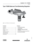
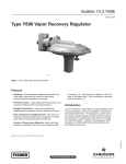
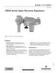
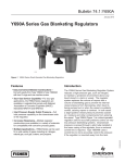
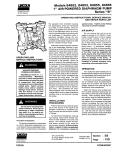
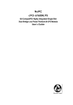
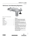
1
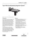
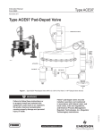
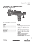
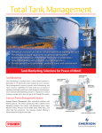
Bulletin 74.3:ACE97
June 2013
type aCe97 Pad-Depad valve
• Bubble Tight Shutoff
• Frictionless Pilot Valve
• Pilot Controlled
• Maximum Vapor
Space Control
• Stainless Steel
• Self-Contained
• Diagnostics
• Fully Balanced
W8161
D102721X012
Figure 1. Type ACE97 Pad-Depad Valve
www.fisherregulators.com
Bulletin 74.3:ACE97
Specifications
Pad Specifications
General Type ACE97 Specifications
Pad Body Sizes
NPS 1/2, 1, and 2 / DN 15, 25, and 50
Pressure Registration
External
Maximum Operating Inlet Pressure(1)
200 psig / 13.8 bar
Temperature Capabilities
Nitrile (NBR):
-20 to 180°F / -29 to 82°C
Fluorocarbon (FKM):
0 to 212°F / -18 to 100°C
Ethylenepropylene (EPDM - FDA):
-20 to 212°F / -29 to 100°C
Perfluoroelastomer (FFKM):
-20 to 212°F / -29 to 100°C
Maximum Main Valve Inlet Pressure(1)
200 psig 13.8 bar
Control Pressure Ranges(1)
See Table 1
Maximum and Minimum Differential Pressures(1)
Minimum: 25 psig / 1.7 bar
Maximum: 200 psig / 13.8 bar
Maximum Backpressure(1)
20 psig / 1.4 bar
Flow Coefficients for Relief Valve Sizing
(110% of rated Cv)
Cv = 0.2 use Cv = 0.22
Cv = 7.5 use Cv = 8.25
Cv = 0.4 use Cv = 0.44
Cv = 10 use Cv = 11
Cv = 1 use Cv = 1.1
Cv = 20 use Cv = 22
Cv = 45 use Cv = 50
Cv = 2 use Cv = 2.2
Cv = 4 use Cv = 4.4
Cv = 60 use Cv = 66
Depad Specifications
Depad Body Sizes
NPS 1, 2, 3, and 4 / DN 25, 50, 80, and 100
Depad Pressure Ranges(1)
See Table 1
Valve Coefficients
NPS 1 / DN 25 body: Cv = 3, Cv = 12, or Cv = 17
NPS 2 / DN 50 body: Cv = 20, Cv = 35, or Cv = 70
NPS 3 / DN 80 body: Cv = 6, Cv = 90, Cv = 115, or Cv = 140
NPS 4 / DN 100 body: Cv = 150, Cv = 200, or Cv = 280
Construction Materials
Pad Body and Bonnet
NPS 1/2 and 1 / DN 15 and 25; Cv = 0.2 and Cv = 0.4:
316L Stainless steel
NPS 1 and 2 / DN 25 and 50; Cv = 1 to 4 and Cv = 5 to 10:
316 Stainless steel
NPS 2 / DN 50; Cv = 20 to 60:
CF3M/CF8M Stainless steel
Depad Body and Bonnet: 316 Stainless steel
Cage: 316 Stainless steel
Actuator: 316 Stainless steel
Trim: stainless steel
Elastomers: Nitrile (NBR), Fluorocarbon (FKM),
Perfluoroelastomer (FFKM), or
Ethylenepropylene (EPDM - FDA)
Diaphragm: Nitrile (NBR), Fluorocarbon (FKM), or
Ethylenepropylene (EPDM - FDA)
Approximate Weights
NPS 1/2 x 1 x 1 / DN 15 x 25 x 25:
70 pounds / 32 kg
NPS 1 x 2 x 2 / DN 25 x 50 x 50:
105 pounds / 48 kg
NPS 2 x 3 x 3 / DN 50 x 80 x 80: 175 pounds / 79 kg
1. The pressure/temperature limits in this Bulletin or any applicable standard limitation should not be exceeded.
Introduction
Features and Benefits
The Type ACE97 Pad-Depad valve is a self-contained, pilotoperated valve that maintains a blanket of inert gas on top of a
stored product to protect it from atmospheric contamination. It
reduces combustibility, decreases vaporization, controls vapor
space pressure during pump-in and pump-out operations, and helps
prevent the tank from entering a vacuum condition and collapsing
upon itself. The Type ACE97 valve provides excellent and accurate
pressure control of the vapor space in the tank. Blanketing pressure
is kept to a minimum in order to conserve the use of blanketing gas.
Pilot Controlled: Type ACE97 valves (NPS 1 / DN 25 and larger)
are pilot-operated for a higher degree of accuracy and control.
Pad (Tank Blanketing) – ensures a minimum pressure is maintained
in the tank vapor space during normal operation.
Depad (Vapor Recovery) – limits tank pressure to a maximum value
during normal operation.
Tank and vapor recovery connections are available to meet most
customer requirements. A Single Array Manifold (SAM) provides
a single tank and sensing connection and is required for tanks
having a single nozzle. Accessories include gauges, purge meters,
pressure switches, and check valves.
2
Fully Balanced: A fully balanced valve eliminates setpoint changes
caused by variations in inlet pressure.
Options and Accessories
Inlet Pressure Gauge: Displays pressure of blanketing gas supply
to the blanketing valve.
Control Pressure Gauge: Low-pressure gauge measures
tank pressure.
Pressure Switch: Allows for the installation of an alarm system to
indicate either low or high-pressure on the tank.
Flow Indicator: Provides a visual indication of blanketing gas flow.
Outlet Check Valve: Prevents corrosive gases and vapors from
flowing back into the blanketing system.
Diagnostic Gauge: Allows analysis of valve operation in the field,
simplifying service and reliability. (Only available on NPS 1 and 2 /
DN 25 and 50 pad valve.)
Bulletin 74.3:ACE97
depad pilot valve
Depad main valve
vent
actuator
gas inlet
pad valve
inlet
filter
E0673
to AND FROM tank
Figure 2. Type ACE97 Pad-Depad Valve Parts
Single Array Manifold (SAM): Provides sense line connection and
main valve connection through a single tank nozzle.
Purge Meters: Prevents corrosive tank vapors from damaging
upstream equipment.
Principle of Operation Pad (Figure 3)
NPS 1 and 2 / DN 25 and 50 Pad Valves (Figure 3)
When tank pressure decreases below the pad setpoint (due to pump
out operations or thermal cooling), the actuator diaphragm moves
downward pushing open the pad pilot. This creates flow from the
pad loading chamber to downstream. When pad loading pressure
decreases, the force created by inlet pressure on the pad main valve
plug overcomes the main spring force and opens the main valve
plug allowing flow through the pad valve to the tank. Once tank
pressure reaches pad setpoint, the pad pilot closes, pad loading
pressure equalizes with inlet pressure and the pad valve closes.
NPS 1/2 / DN 15 Pad Valves (Not Shown)
moves downward pushing the valve plug open and allowing flow
through the pad valve to the tank.
Depad (Figure 4)
When tank pressure increases above the depad setpoint (due to
pump-in operations or thermal heating), the actuator diaphragm
moves upward and pushes open the depad pilot. This releases
depad loading pressure (nitrogen or other supply gas). When depad
pilot loading pressure decreases, the depad main valve opens by a
spring and allows flow from the tank to the vent or recovery system.
Diagnostics
Tank blanketing valves are often installed in locations that are
difficult to access. Type ACE97 valves are available with a
diagnostics feature that allows analysis of valve operation in the
field, making maintenance easier and more reliable.
The diagnostics feature relies uses relationship of pressure in
the pilot and main valve chambers to analyze valve performance.
The NPS 1/2 / DN 15 Pad valve has a main valve only. When tank
pressure decreases below the pad setpoint the actuator diaphragm
3
Bulletin 74.3:ACE97
loading pressure
exhausted back to tank
on/off
diagnostic
gauge
depad pilot
adjustable
deadband
poppet
cage
controlled
pressure
range spring
regulator
depad
main
valve
o-ring seat
inlet
vent
actuator
inlet
bleed
rolling
diaphragm
sensing
connection
open pilot
E0005
diagnostic
port
main valve
spring
INLET PRESSURE
ATMOSPHERIC PRESSURE
TANK PRESSURE
PILOT LOADING PRESSURE
inert gas in
VENT HEADER PRESSURE
tank
connection
pad valve
INLET BLEED PRESSURE
Figure 3. Type ACE97 Pad On / Depad Off
loading pressure
exhausted back to tank
depad pilot
controlled
pressure
range spring
regulator
cage
poppet
depad
main
valve
Vent
actuator
o-ring
seat
inlet
on/off
diagnostic
gauge
rolling
diaphragm
sensing
connection
diagnostic
port
closed pilot
main valve
spring
E0004
INLET PRESSURE
ATMOSPHERIC PRESSURE
TANK PRESSURE
PILOT LOADING PRESSURE
VENT HEADER PRESSURE
Figure 4. Type ACE97 Pad Off / Depad On
4
inert gas in
pad valve
tank
connection
Bulletin 74.3:ACE97
Table 1. Control Pressure Ranges
Controlled Pressure RANGEs
Pad Setpoint
Depad Setpoint (Above Pad)
SPRING FREE LENGTH
SPRING WIRE DIAMETER
Inch w.c.
mbar
Inch w.c.
mbar
Inch
mm
Inch
mm
0.5 to 3
1 to 7
4 to 10
10 to 25
3.08
78.2
0.105
2.67
0.5 to 7
1 to 17
4 to 6
10 to 15
4.00
102
0.092
2.34
3 to 13
7 to 32
4 to 16
10 to 40
3.73
94.7
0.156
3.96
4 to 10
10 to 25(1)
16 to 78
40 to 194(1)
3.73
94.7
0.156
3.96
2.90
73.7
4 to 10
10 to 25(1)
16 to 78
40 to 194(1)
0.5 to 1.4 psig
0.03 to 0.10 bar
0.25 to 1 psig
0.02 to 0.07 bar
1.0 to 2.2 psig
0.07 to 0.15 bar
0.25 to 2.0 psig
0.02 to 0.14 bar
3.80
96.5
0.250
6.35
0.250
6.35
0.313
7.95
1. Two nested springs are used.
System Sizing
Tank Blanketing systems must be properly sized to have
capacity to supply enough blanketing gas to maintain the
setpoint pressure, yet large enough to vent excess gas without
having tank vapor space pressure rise above allowable limits. Pad valves must not be so large that they cause overpressure. Sizing must also take into account applicable codes and
standards as they apply to the installation.
For proper sizing of the pad and depad valves, certain
information is required. Proper sizing is essential to protect the
product, the tank, the environment, and personnel.
Sizing Information
The following list contains all necessary information to properly size
a valve once system parameters are determined. The customer
must provide the following:
•
•
•
•
•
•
•
•
•
•
•
Pump-in rate (for depad calculation)
Pump-out rate (for pad calculation)
Inert (blanketing) gas specific gravity
Inert gas supply pressure (for pad selection)
Tank volume (for API sizing both pad and depad)
Stored fluid flash point (for API sizing depad)
Stored fluid boiling point (for API sizing depad)
Vent gas specific gravity (SG) (for API sizing depad)
Depad setpoint
Vent piping backpressure
Sizing method (Direct Displacement or API 2000)
Direct Displacement
The direct displacement method should be used with extreme
caution. The direct displacement method determines the amount
of blanketing gas required to replace liquid pumped out of the tank
and the amount of gas that must be removed due to liquid pump in. Direct displacement does not account for fluctuating temperature
or other factors that may affect pressure in the vapor space. This
method is typically applied to tanks containing non-flammable,
non-volatile products.
Pad Sizing
Qpad = Qpump-out
where,
Qpad = Required Pad Flow Rate
Qpump-out = Required Flow Rate for displacement due to
pump-out (See Table 2)
Depad Sizing
Qdepad = Qpump-in
where,
Qdepad = Required Depad Flow Rate
Qpump-out = Required Flow Rate for displacement due to
liquid pump-in. (See Table 2)
API 2000
The American Petroleum Institute Standard 2000 (API 2000)
sizing criteria accounts for liquid pump-in and pump-out as well
as contraction and expansion of tank vapors due to heating and
cooling. When using API 2000 methods:
Pad Sizing
Qpad = Qpump-out + Qthermal
where,
Qpad = Required Pad Flow Rate
Qpump-out = Required Flow Rate for displacement due to
pump-out (See Table 5)
Qthermal = Required Flow Rate due to thermal cooling
(See Table 6)
Depad Sizing
Qdepad = Qpump-in + Qthermal
where,
Qpad = Required Depad Flow Rate
Qpump-in = Required Pump-In Rate (See Table 5)
Qthermal = Required Flow Rate due to thermal expansion
(See Table 6)
Supplemental Venting
Depending on the method, there can be a significant difference
in the calculated required capacity. No matter which method is
used, the tank must be equipped with supplemental venting to
protect the tank, product, and personnel in cases of equipment
failure, fire exposure, or other conditions that could cause the
tank pressure or vacuum to exceed operating limits.
Capacity Information
Pad Valves
In the case of pad valves, the tables are based on 0.97 specific
gravity nitrogen. If it is desired to convert nitrogen flow rates of
another gas, multiply the flow rate value from the capacity table by the
following correction factor in Table 3.
Depad Valves
In the case of depad valves, the tables are based on air (1.0 specific
gravity). Always use the differential pressure between tank pressure
(depad setpoint) and vent header (vapor recovery) pressure to
calculate flow through the depad valve.
5
Bulletin 74.3:ACE97
Table 2. Flow Rate Conversion
multiply maximum pump rate
U.S. GPM
U.S. GPH
m3/hr
Barrels/hr
Barrels/day
by
8.021
0.1337
1.01
5.615
0.2340
to obtaiN:
SCFH
SCFH
Nm3/h
SCFH
SCFH
Table 3. C
orrection Factors (For Converting Nitrogen Flow Rates to Other Gas Flow Rates)
BLANKET GAS
Natural Gas
Air
Dry CO2
SPECIFIC GRAVITY
0.60
1.00
1.52
Correction Factor =
CORRECTION FACTOR
1.27
0.99
0.80
0.985
SG
Table 4. C
orrection Factors (For Converting Air Flow Rates to Other Gas Flow Rates)
VENT GAS SPECIFIC GRAVITY
0.60
0.80
1.20
1.40
1.60
1.80
2.00
3.00
CORRECTION FACTOR
1.29
1.19
0.91
0.85
0.79
0.75
0.71
0.58
Correction Factor =
1.00
SG
Table 5. Flow Rate Requirements for Liquid Pump-In Pump-Out per API 2000
Pump-Out (Inbreathing)
Pump-In (Outbreathing)
Flashpoint > 100°F / 38°C or
Normal Boiling Point > 300°F / 149°C
5.6 SCFH / 0.15 Nm3/h of air per barrel/hour of liquid
8.0 SCFH / 0.21 Nm3/h of air per GPM of liquid
35.1 SCFH / 0.94 Nm3/h of air per m3/hr of liquid
6 barrels/hour of SCFH air per barrel/hour of liquid
8.6 SCFH / 0.23 Nm3/h of air per GPM of liquid
37.7 SCFH / 1.01 Nm3/h of air per m3/hr of liquid
Flashpoint < 100°F / 38°C or
Normal Boiling Point < 300°F / 149°C
5.6 SCFH / 0.15 Nm3/h of air per barrel/hour of liquid
8.0 SCFH / 0.21 Nm3/h of air per GPM of liquid
35.1 SCFH / 0.94 Nm3/h of air per m3/hr of liquid
12 SCFH / 0.32 Nm3/h of air per barrel/hour of liquid
17 SCFH / 0.46 Nm3/h of air per GPM of liquid
75.3 SCFH / 2.02 Nm3/h of air per m3/hr of liquid
Table 6. Gas Flow Required for Thermal Cooling (Inbreathing) or Heating (Outbreathing) per API 2000 (Interpolate for Intermediate Sizes)
VESSEL CAPACITY
6
Barrels
Gallons
Liters
60
100
500
1000
2000
3000
4000
5000
10,000
15,000
20,000
25,000
30,000
35,000
40,000
45,000
50,000
60,000
70,000
80,000
90,000
100,000
120,000
140,000
160,000
180,000
2520
4200
21,000
42,000
84,000
126,000
168,000
210,000
420,000
630,000
840,000
1,050,000
1,260,000
1,470,000
1,680,000
1,890,000
2,100,000
2,520,000
2,940,000
3,360,000
3,780,000
4,200,000
5,040,000
5,880,000
6,720,000
7,560,000
9500
16,000
79,500
159,000
318,000
477,000
636,000
795,000
1,590,000
2,385,000
3,180,000
3,975,000
4,769,000
5,564,000
6,359,000
7,154,000
7,949,000
9,539,000
11,129,000
12,719,000
14,309,000
15,899,000
19,079,000
22,258,000
25,438,000
28,618,000
Inbreathing
SCFH
60
100
500
1000
2000
3000
4000
5000
10,000
15,000
20,000
24,000
28,000
31,000
34,000
37,000
40,000
44,000
48,000
52,000
56,000
60,000
68,000
75,000
82,000
90,000
Nm³/h
1.61
2.68
13.4
26.8
53.6
80.4
107
134
268
402
536
643
750
831
911
992
1072
1179
1286
1394
1501
1608
1822
2010
2198
2412
AIR FLOW RATE REQUIRED
Outbreathing
Flashpoint < 100°F / 38°C or
Flashpoint > 100°F / 38°C or
Normal Boiling Point
Normal Boiling Point
< 300°F / 149°C
> 300°F / 149°C
SCFH
Nm³/h
SCFH
Nm³/h
1.61
40
1.07
60
1.61
100
2.68
60
300
8.04
500
13.4
26.8
600
16.1
1000
32.2
2000
53.6
1200
80.4
1800
48.2
3000
2400
64.3
4000
107
3000
80.4
5000
134
268
6000
161
10,000
9000
241
15,000
402
20,000
536
12,000
322
15,000
402
24,000
643
17,000
456
28,000
750
31,000
831
19,000
509
911
21,000
563
34,000
616
37,000
992
23,000
24,000
643
40,000
1072
27,000
724
44,000
1179
777
48,000
1286
29,000
1394
31,000
831
52,000
34,000
911
56,000
1501
36,000
965
60,000
1608
41,000
1099
68,000
1822
45,000
1206
75,000
2010
50,000
1340
82,000
2198
54,000
1447
90,000
2412
Bulletin 74.3:ACE97
Table 7. NPS 1/2 / DN 15 Pad Valve Capacities of 0.97 Specific Gravity Nitrogen
INLET PRESSURE
psig
25
30
40
50
60
70
80
90
100
120
140
160
180
200
bar
1.7
2.1
2.8
3.4
4.1
4.8
5.5
6.2
6.9
8.3
9.7
11.0
12.4
13.8
kg/cm2
1.8
2.1
2.8
3.5
4.2
4.9
5.6
6.3
7.0
8.4
9.8
11.2
12.7
14.1
kPa
172
207
276
345
414
483
552
621
690
828
966
1103
1241
1379
SCFH
250
290
370
450
530
610
690
780
860
1020
1180
1340
1500
1660
CAPACITIES IN SCFH / Nm3/h OF NITROGEN
Cv = 0.2
Cv = 0.4
Nm3/h
SCFH
6.7
550
7.8
630
9.9
780
12.1
930
14.2
1070
16.3
1230
18.5
1390
20.9
1560
23.0
1720
27.3
2040
31.6
2360
35.9
2680
40.2
3000
44.5
3330
Nm3/h
14.7
16.9
20.9
24.9
28.7
33.0
37.3
41.8
46.1
54.7
63.2
71.8
80.4
89.2
Table 8. NPS 1 / DN 25 Pad Valve Capacities of 0.97 Specific Gravity Nitrogen
INLET PRESSURE
CV = 1
psig
bar
kg/cm2
kPa
SCFH
Nm3/h
25
1.7
1.76
172
1330
35.6
30
2.1
2.11
207
1510
40.5
40
2.8
2.81
276
1870
50.1
50
3.4
3.52
345
2280
61.1
2690
72.1
60
4.1
4.22
414
70
4.8
4.92
483
3090
82.8
93.5
5.5
5.62
552
3490
80
6.2
6.33
621
3900
105
90
690
4300
115
100
6.9
7.03
759
4700
126
7.73
110
7.6
137
8.3
8.44
827
5100
120
5510
148
9.14
897
130
9.0
158
9.84
965
5910
140
9.7
169
1034
6310
150
10.3
10.55
1103
6710
180
11.0
11.25
160
7120
191
11.7
11.95
1172
170
7520
202
12.65
1241
180
12.4
212
13.1
13.36
1310
7920
190
8320
223
1379
200
13.8
14.06
Typical accuracy when flowing 5 to 70% of table value is ± 0.5 inch w.c. / 1 mbar.
CV = 2
SCFH
2670
3020
3750
4570
5380
6180
6990
7800
8600
9410
10,200
11,000
11,800
12,600
13,400
14,200
15,000
15,800
16,600
CAPACITIES IN SCFH / Nm3/h OF NITROGEN
CV = 4
CV = 7.5
Nm3/h
SCFH
Nm3/h
SCFH
Nm3/h
71.6
5350
143
10,000
268
80.9
6050
162
11,300
303
101
7510
201
14,000
375
122
9140
245
17,100
458
20,100
539
144
10,700
287
23,200
622
166
12,300
330
187
13,900
373
26,200
702
783
209
15,600
418
29,200
230
17,200
461
32,200
863
504
35,300
946
252
18,800
38,300
1026
273
20,400
547
590
41,300
1107
22,000
295
1187
316
23,600
632
44,300
47,300
1268
25,200
675
338
26,800
718
50,300
1348
359
1431
53,400
381
28,400
761
804
56,400
1512
402
30,000
59,400
1592
423
31,700
850
62,400
1672
33,300
892
445
CV = 10
SCFH
Nm3/h
13,000
348
15,100
405
18,700
501
22,800
611
26,900
721
30,000
804
34,900
935
39,000
1045
1152
43,000
47,000
1260
51,000
1367
1477
55,100
59,100
1584
63,100
1691
67,100
1798
71,200
1908
2015
75,200
79,200
2123
2230
83,200
Table 9. NPS2 / DN 50 Pad Valve Capacities of 0.97 Specific Gravity Nitrogen
INLET PRESSURE
psig
bar
kg/cm2
kPa
SCFH
25
1.7
1.76
172
26,700
30
2.1
2.11
207
30,200
40
2.8
2.81
276
37,500
50
3.4
3.52
345
45,700
53,800
60
4.1
4.22
414
70
4.8
4.92
483
61,800
80
5.5
5.62
552
69,900
90
6.2
6.33
621
78,000
6.9
7.03
690
86,000
100
125
8.6
8.79
862
102,100
150
10.3
10.55
1034
126,300
175
12.1
12.31
1207
142,400
200
13.8
14.06
1379
166,500
Typical accuracy when flowing 5 to 70% of table value is ± 0.5 inch w.c. / 1 mbar.
CV = 20
Nm3/h
716
809
1005
1225
1442
1656
1873
2090
2305
2736
3385
3816
4462
CAPACITIES IN SCFH / Nm3/h OF NITROGEN
CV = 45
CV = 60
SCFH
Nm3/h
SCFH
60,200
1613
80,000
68,100
1825
90,800
84,500
2265
112,700
102,800
2755
137,100
121,000
3243
161,400
139,200
3731
185,600
154,400
4138
209,800
175,500
4703
234,000
258,200
193,600
5188
238,900
6403
306,500
284,200
7617
378,900
329,400
8828
427,200
347,700
9318
499,600
Nm3/h
2144
2433
3020
3674
4326
4974
5623
6271
6920
8214
10,155
11,449
13,389
7
Bulletin 74.3:ACE97
Table 10. NPS 1 / DN 25 Depad Valve Capacities of 1.0 Specific Gravity Air
flow capacity in scfh / Nm3/h of 1.0 specific gravity air
differential
pressure(1)
Cv = 3
Cv = 6
Cv = 12
Cv = 17
Inch w.c.
mbar
SCFH
Nm /h
SCFH
Nm /h
SCFH
Nm /h
SCFH
Nm3/h
2
3
4
5
5
7
10
12
180
220
250
280
4.8
5.9
6.7
7.5
360
440
510
570
9.6
11.8
13.7
15.3
730
890
1030
1150
19.6
23.9
27.6
30.8
1030
1260
1460
1630
27.6
33.8
39.1
43.7
6
7
8
9
10
15
17
20
22
25
310
340
360
380
400
8.3
9.1
9.6
10.2
10.7
630
680
730
770
810
16.9
18.2
19.6
20.6
21.7
1260
1360
1460
1540
1630
33.8
36.4
39.1
41.3
43.7
1790
1930
2060
2190
2310
48.0
51.7
55.2
58.7
61.9
12
14
16
18
20
30
35
40
45
50
440
480
510
540
570
11.8
12.9
13.7
14.5
15.3
890
960
1030
1090
1150
23.9
25.7
27.6
29.2
30.8
1780
1930
2060
2190
2300
47.7
51.7
55.2
58.7
61.6
2530
2730
2920
3100
3270
67.8
73.2
78.3
83.1
87.6
22
24
26
28
30
55
60
65
70
75
600
630
650
680
700
16.1
16.9
17.4
18.2
18.8
1210
1260
1310
1360
1410
32.4
33.8
35.1
36.5
37.8
2420
2520
2630
2730
2820
64.9
67.5
70.5
73.2
75.6
3430
3580
3720
3870
4000
91.9
95.9
99.7
104
107
1.0 psig
1.1 psig
1.2 psig
1.3 psig
1.4 psig
69
76
83
90
97
670
710
740
770
800
18.0
19.0
19.8
20.6
21.4
1350
1420
1480
1540
1600
36.2
38.1
39.7
41.3
42.9
2710
2840
2970
3090
3210
72.6
76.1
79.6
82.8
86.0
3840
4030
4210
4380
4550
103
108
113
117
122
1.5 psig
1.6 psig
1.7 psig
1.8 psig
1.9 psig
103
110
117
124
131
830
850
880
910
930
22.2
22.8
23.6
24.4
24.9
1660
1710
1770
1820
1870
44.5
45.8
47.4
48.8
50.1
3320
3430
3540
3640
3740
89.0
91.9
94.9
97.6
100
4710
4870
5020
5160
5300
126
130
134
138
142
2.0 psig
2.1 psig
2.2 psig
2.3 psig
2.4 psig
138
145
152
159
165
960
980
1000
1030
1050
25.7
26.3
26.8
27.6
28.1
1920
1970
2010
2060
2100
51.5
52.8
53.9
55.2
56.3
3840
3940
4030
4120
4210
103
106
108
110
113
5440
5580
5710
5840
5970
146
149
153
156
160
2.5 psig
2.6 psig
2.7 psig
2.8 psig
172
179
186
193
1070
1090
1110
1130
28.7
29.2
29.7
30.3
2150
2190
2230
2270
57.6
58.7
59.8
60.8
4300
4380
4470
4550
115
117
120
122
6090
6210
6330
6450
163
166
170
173
3
3
3
1. Always use the differential pressure between tank pressure (depad setpoint) and vent header (vapor recovery) pressure to calculate flow through the depad valve.
8
Bulletin 74.3:ACE97
Table 11. NPS 2 / DN 50 Depad Valve Capacities of 1.0 Specific Gravity Air
flow capacity in scfh / Nm3/h of 1.0 specific gravity air
differential pressure(1)
Cv = 20
Cv = 35
Cv = 70
Inch w.c.
mbar
scfh
Nm /h
scfh
Nm /h
scfh
Nm3/h
2
3
4
5
5
7
10
12
1210
1490
1720
1920
32.4
39.9
46.1
51.5
2130
2600
3010
3360
57.1
69.7
80.7
90.0
4260
5210
6020
6730
114
140
161
180
6
7
8
9
10
15
17
20
22
25
2100
2270
2430
2580
2720
56.3
60.8
65.1
69.1
72.9
3680
3980
4260
4510
4760
98.6
107
114
121
128
7370
7970
8520
9030
9520
198
214
228
242
255
12
14
16
18
20
30
35
40
45
50
2980
3220
3440
3650
3840
79.9
86.3
92.2
97.8
103
5210
5630
6020
6380
6730
140
151
161
171
180
10,430
11,270
12,040
12,770
13,470
280
302
323
342
361
22
24
26
28
30
55
60
65
70
75
4030
4210
4380
4550
4710
108
113
117
122
126
7060
7370
7670
7960
8240
189
198
206
213
221
14,120
14,750
15,350
15,930
16,490
378
395
411
427
442
1.0 psig
1.1 psig
1.2 psig
1.3 psig
1.4 psig
69
76
83
90
97
4520
4740
4960
5160
5350
121
127
133
138
143
7920
8310
8680
9030
9370
212
223
233
242
251
15,800
16,600
17,300
18,000
18,700
423
445
464
482
501
1.5 psig
1.6 psig
1.7 psig
1.8 psig
1.9 psig
103
110
117
124
131
5540
5720
5900
6070
6240
148
153
158
163
167
9700
10,000
10,300
10,600
10,900
260
268
276
284
292
19,400
20,000
20,600
21,200
21,800
520
536
552
568
584
2.0 psig
2.1 psig
2.2 psig
2.3 psig
2.4 psig
138
145
152
159
165
6400
6560
6720
6870
7020
172
176
180
184
188
11,200
11,400
11,700
12,000
12,200
300
306
314
322
327
22,400
22,900
23,500
24,000
24,500
600
614
630
643
657
2.5 psig
2.6 psig
2.7 psig
2.8 psig
172
179
186
193
7170
7310
7450
7590
192
196
200
203
12,500
12,700
13,000
13,200
335
340
348
354
25,000
25,500
26,000
26,500
670
683
697
710
3
3
1. Always use the differential pressure between tank pressure (depad setpoint) and vent header (vapor recovery) pressure to calculate flow through the depad valve.
9
Bulletin 74.3:ACE97
Table 12. NPS 3 / DN 80 Depad Valve Capacities of 1.0 Specific Gravity Air
flow capacity in scfh / Nm3/h of 1.0 specific gravity air
differential pressure(1)
Cv = 90
Cv = 115
Cv = 140
Inch w.c.
mbar
scfh
Nm /h
scfh
Nm /h
scfh
Nm3/h
2
3
4
5
5
7
10
12
5400
6700
7700
8600
145
180
206
230
7000
8500
9800
11,000
188
228
263
295
8500
10,400
12,000
13,400
228
279
322
359
6
7
8
9
10
15
17
20
22
25
9400
10,200
10,900
11,600
12,200
252
273
292
311
327
12,100
13,000
13,900
14,800
15,600
324
348
373
397
418
14,700
15,900
17,000
18,000
19,000
394
426
456
482
509
12
14
16
18
20
30
35
40
45
50
13,400
14,400
15,400
16,400
17,300
359
386
413
440
464
17,100
18,500
19,700
20,900
22,100
458
496
528
560
592
20,800
22,500
24,000
25,500
26,900
557
603
643
683
721
22
24
26
28
30
55
60
65
70
75
18,100
18,900
19,700
20,400
21,200
485
507
528
547
568
23,200
24,200
25,200
26,100
27,100
622
649
675
699
726
28,200
29,500
30,700
31,800
32,900
756
791
823
852
882
1.0 psig
1.1 psig
1.2 psig
1.3 psig
1.4 psig
69
76
83
90
97
20,300
21,300
22,300
23,200
24,100
544
571
598
622
646
26,000
27,300
28,500
29,600
30,800
697
732
764
793
825
31,600
33,200
34,700
36,100
37,500
847
890
930
967
1005
1.5 psig
1.6 psig
1.7 psig
1.8 psig
1.9 psig
103
110
117
124
131
24,900
25,700
26,500
27,300
28,100
667
689
710
732
753
31,800
32,900
33,900
34,900
35,900
852
882
909
935
962
38,800
40,100
41,300
42,500
43,700
1040
1074
1107
1139
1171
2.0 psig
2.1 psig
2.2 psig
2.3 psig
2.4 psig
138
145
152
159
165
28,800
29,500
30,200
30,900
21,600
772
791
809
828
579
36,800
37,700
38,600
39,500
40,300
986
1010
1034
1059
1080
44,800
45,900
47,000
48,100
49,100
1201
1230
1260
1289
1316
2.5 psig
2.6 psig
2.7 psig
2.8 psig
172
179
186
193
32,200
32,900
33,500
34,100
863
882
898
914
41,200
42,000
42,800
43,600
1104
1126
1147
1168
50,100
51,100
52,100
53,100
1343
1369
1396
1423
3
3
1. Always use the differential pressure between tank pressure (depad setpoint) and vent header (vapor recovery) pressure to calculate flow through the depad valve.
10
Bulletin 74.3:ACE97
Table 13. NPS 4 / DN 100 Depad Valve Capacities of 1.0 Specific Gravity Air
flow capacity in scfh / Nm3/h of 1.0 specific gravity air
differential pressure(1)
Cv = 150
Cv = 200
Cv = 280
Inch w.c.
mbar
SCFH
Nm /h
SCFH
Nm /h
SCFH
Nm3/h
2
3
4
5
5
7
10
12
9100
11,100
12,900
14,400
244
297
346
386
12,100
14,900
17,200
19,200
324
399
461
515
17,000
20,800
24,100
26,900
456
557
646
721
6
7
8
9
10
15
17
20
22
25
15,800
17,000
18,200
19,300
20,400
423
456
488
517
547
21,000
22,700
24,300
25,800
27,200
563
608
651
691
729
29,500
31,800
34,000
36,100
38,100
791
852
911
967
1021
12
14
16
18
20
30
35
40
45
50
22,300
24,100
25,800
27,300
28,800
598
646
691
732
772
29,800
32,200
34,400
36,500
38,400
799
863
922
978
1029
41,700
45,000
48,100
51,100
53,800
1118
1206
1289
1369
1442
22
24
26
28
30
55
60
65
70
75
30,200
31,600
32,900
34,100
35,300
809
847
882
914
946
40,300
42,100
43,800
45,500
47,100
1080
1128
1174
1219
1262
56,500
59,000
61,400
63,700
65,900
1514
1581
1646
1707
1766
1.0 psig
1.1 psig
1.2 psig
1.3 psig
1.4 psig
69
76
83
90
97
33,900
35,600
37,200
38,700
40,100
909
954
997
1037
1075
45,200
47,400
49,600
51,600
53,500
1211
1270
1329
1383
1434
63,300
66,400
69,400
72,200
75,000
1696
1780
1860
1935
2010
1.5 psig
1.6 psig
1.7 psig
1.8 psig
1.9 psig
103
110
117
124
131
41,600
42,900
44,300
45,500
46,800
1115
1150
1187
1219
1254
55,400
57,200
59,000
60,700
62,400
1485
1533
1581
1627
1672
77,600
80,200
82,600
85,100
87,400
2080
2149
2214
2281
2342
2.0 psig
2.1 psig
2.2 psig
2.3 psig
2.4 psig
138
145
152
159
165
48,000
49,200
50,400
51,500
52,600
1286
1319
1351
1380
1410
64,000
65,600
67,200
68,700
70,200
1715
1758
1801
1841
1881
89,700
91,900
94,100
96,200
98,300
2404
2463
2522
2578
2634
2.5 psig
2.6 psig
2.7 psig
2.8 psig
172
179
186
193
53,700
54,800
55,900
56,900
1439
1469
1498
1525
71,700
73,100
74,500
75,900
1922
1959
1997
2034
100,300
102,300
104,300
106,200
2688
2742
2795
2846
3
3
1. Always use the differential pressure between tank pressure (depad setpoint) and vent header (vapor recovery) pressure to calculate flow through the depad valve.
11
Bulletin 74.3:ACE97
18.7 / 174
12.5 / 318
1/2 NPT
SENSING
CONNECTION
NPS 1 / DN 25,
CL150 RF VAPOR
RECOVERY
CONNECTION
22.5 / 572
C
6.0 / 152
B
TANK
CONNECTION
1 NPT
BLANKETING GAS
CONNECTION
A
1/2 NPT
SENSING
CONNECTION
7.2 / 183
3.0 / 76
2.5 / 64
NPS 1 x 1 x 1 OR 2 / DN 25 x 25 x 25 OR 50 with options
12.5 / 318
24.1 / 612
12.3 / 312
VAPOR
RECOVERY
CONNECTION
1/2 NPT
SENSING
CONNECTION
C
1/2 NPT
SENSING
CONNECTION
B
8.1 / 206
TANK
CONNECTION
1 NPT
BLANKETING GAS
CONNECTION
2.5 / 64
7.2 / 183
6.3 / 160
A
INCHES / mm
NPS 1 x 3 x 3 OR 4 / DN 25 x 80 x 80 OR 100 with options
Figure 5. Type ACE97 Pad/Depad Valve Dimensions
Table 14. Type ACE97 Pad/Depad Valve Dimensions
DIMENSIONS IN INCH / mm FOR NPS 1 x 1 x 1 OR 2 / DN 25 x 25 x 25 OR 50 BODy WITH OPTIONS
A
B
C
NPT
CL150 RF
NPT
CL150 RF
NPT
CL150 RF
9.4 / 239
11.5 / 292
0.3 / 7.6
2.8 / 71
6.3 / 160
8.8 / 224
DIMENSIONS IN INCH / mm FOR NPS 1 x 3 x 3 or 4 / DN 25 x 80 x 80 OR 100 BODy WITH OPTIONS
A
12
B
C
4 NPT
NPS 3 or 4 /
DN 80 or 100,
CL150 RF
5.8 / 147
15.6 / 396
1 NPT
NPS 1 / DN 25,
CL150 RF
NPS 1-1/2 / DN 40,
CL150 RF
NPS 2 / DN 50,
CL150 RF
3 NPT
NPS 3 or 4 /
DN 80 or 100,
CL150 RF
11.5 / 292
16.9 / 429
17.2 / 437
17.4 / 442
5.3 / 135
4.9 / 124
Bulletin 74.3:ACE97
12.5 / 318
13.3 / 337
BLANKETING GAS
CONNECTION
VAPOR
RECOVERY
CONNECTION
1/2 NPT
SENSING
CONNECTION
C
B
7.3 / 185
TANK
CONNECTION
A
8.0 / 203
3.0 / 76
2.5 / 64
NPS 1/2 x 1 x 1 OR 2 / DN 15 x 25 x 25 OR 50 with options
12.5 / 318
NPS 1 or 2 /
DN 25 or 50,
CL150 RF VAPOR
RECOVERY
CONNECTION
BLANKETING GAS
CONNECTION
13.3 / 337
C
B
A
8.0 / 203
3.0 / 76
INCHES / mm
TANK
CONNECTION
NPS 1/2 x 1 x 2 / DN 15 x 25 x 50 WITH SINGLE ARRAY MANIFOLD
Figure 5. Type ACE97 Pad/Depad Valve Dimensions (continued)
Table 14. Type ACE97 Pad/Depad Valve Dimensions (continued)
DIMENSIONS IN INCH / mm FOR NPS 1/2 x 1 x 1 OR 2 / DN 15 x 25 x 25 OR 50 BODy WITH OPTIONS
A
B
1/2 NPT
Without Filter
1/2 NPT
With Filter
NPS 1/2 / DN 15,
CL150 RF
Without Filter
10.4 / 264
14.2 / 360
14 / 356
NPS 1/2 / DN 15,
CL150 RF
With Filter
15.9 / 404
C
1 NPT
NPS 1 or 2 /
DN 25 or 50,
CL150 RF
1 NPT
NPS 1 or 2 /
DN 25 or 50,
CL150 RF
3.7 / 93
8 / 203
6.3 / 160
10.6 / 269
DIMENSIONS IN INCH / mm FOR NPS 1/2 x 1 x 2 / DN 15 x 25 x 50 BODY WITH SINGLE ARRAY MANIFOLD
A
B
1/2 NPT
Without Filter
1/2 NPT
With Filter
NPS 1/2 or 1 /
DN 15 or 25,
CL150 RF
Without Filter
10.4 / 264
14.2 / 360
14 / 356
C
NPS 1/2 or 1 /
DN 15 or 25,
CL150 RF
With Filter
1 NPT
NPS 1 or 2 /
DN 25 or 50,
CL150 RF
NPS 2 /
DN 50,
CL150 RF
15.9 / 404
3.7 / 93
8 / 203
12.6 / 320
13
Bulletin 74.3:ACE97
Information Required
In order to complete the specification worksheet, the following information must be provided. Operating pressures and temperatures
must be within the ranges listed within this bulletin.
Please specify measurement units: Imperial (USA) _____ or Metric _____
Pad Information
1. Maximum Inert Gas Flow - SCFH or Nm3/hr: _____________ or Pad Valve Cv: _____________
2. Inert Gas: _____________ or Inert Gas Specific Gravity: _____________
3. Supply Pressure, Inert Gas - Maximum: _____________ Minimum: _____________
4. Operating Temperature - °F: _____________ or °C: _____________
5. Pad Setpoint: _____________ inches w.c. or mbar
Depad Information
6. Maximum Vent Gas Flow - SCFH or Nm3/hr: _____________ or Depad Valve Cv: _____________
7. Vent Gas Specific Gravity: _____________
8. Vent Gas Temperature - °F: _____________ or °C: _____________
9. Depad Setpoint: _____________ inches w.c. or mbar
10. Relief Header Pressure at Depad Outlet, Flowing Conditions, Maximum: _________ inches w.c. or mbar
11. Stored Liquid Flash Point - °F: _____________ or °C: _____________ or
Stored Liquid Boiling Point - °F: _____________ or °C: _____________ (Require at least one for API sizing)
12. Storage Temperature of Product - °F: _____________ or °C: _____________
13. Depad Materials of Construction Compatible with Stored Liquid and Vapors Metals: 316 SST or _____________
Elastomers: Nitrile (NBR) _____, Fluorocarbon (FKM) _____, Ethylenepropylene (EPDM-FDA) _____, Perfluoroelastomer (FFKM) _____, or Other __________________
14. Product to be Blanketed: _____________
15. Optional Equipment Required: _____________
16. Emergency Pressure Vent Setpoint: _____________ inches w.c. (separate device)
Connections
17. Inert Gas Supply - NPT: ___________
Flanged: ___________ Other (specify): ___________
18. Tank Connection - NPT: ___________
Flanged: ___________ Other (specify): ___________
19. Header Connection - NPT: ___________
Flanged: ___________ Other (specify): ___________
Notes
If the required Pad or Depad valve Cv value is unknown, refer to the Sizing section for more details or contact your local Sales Office. If the required Pad or Depad valve Cv value is known, continue with the Ordering worksheet.
14
Bulletin 74.3:ACE97
Ordering Guide
Pad and Depad Valve Bodies (Select One)
CF8M Stainless steel
CF3M Stainless steel
Body Size and Coefficient (Select One from Each Category)
Pad Valve Body
NPS 1/2 / DN 15
NPS 1 / DN 25
NPS 2 / DN 50
Cv = 0.4 Cv = 1 Cv = 20
Cv = 2 Cv = 45
Cv = 0.2 Cv = 4 Cv = 60
Cv = 7.5
Cv = 10
Depad Valve Body
NPS 1 / DN 25
NPS 2 / DN 50
Cv = 20
Cv = 3 Cv = 6 Cv = 35
Cv = 70
Cv = 12 Cv = 17
NPS 3 / DN 80
NPS 4 / DN 100
Cv = 150
Cv = 90 Cv = 115 Cv = 200
Cv = 140 Cv = 280
Pad Inlet Connection (Select One)
NPS 1/2 / DN 15 Body Size
NPT
CL150 RF threaded flange and nipple
NPS 1 / DN 25 Body Size
NPT
CL150 RF threaded flange and nipple
NPS 2 / DN 50 Body Size
NPT
CL150 RF threaded flange and nipple
Tank Connection (Must Match or be Larger than the Largest Pad or
Depad Valve Body Size)
NPS 1 / DN 25, CL150 RF
NPS 2 / DN 50, CL150 RF
NPS 3 / DN 80, CL150 RF
NPS 4 / DN 100, CL150 RF
Diaphragm (Select One)
Nitrile (NBR)
Ethylenepropylene (EPDM - EPA)
Fluorocarbon (FKM)
Other Elastomers (Select One)
Nitrile (NBR)
Ethylenepropylene (EPDM - EPA)
Fluorocarbon (FKM)
Perfluoroelastomer (FFKM)
Control Pressure Ranges - Pad Setpoint and Depad Setpoint
(above Pad Setpoint) (Select One)
Pad Setpoint: 0.5 to 3-inches w.c. / 1 to 7 mbar
Depad Setpoint: 4 to 10-inches w.c. / 10 to 25 mbar
Pad Setpoint: 0.5 to 7-inches w.c. / 1 to 17 mbar
Depad Setpoint: 4 to 6-inches w.c. / 10 to 15 mbar
Pad Setpoint: 3 to 13-inches w.c. / 7 to 32 mbar
Depad Setpoint: 4 to 16-inches w.c. / 10 to 40 mbar
Pad Setpoint: 4 to 10-inches w.c. / 10 to 25 mbar
Depad Setpoint: 16 to 78-inches w.c. / 40 to 194 mbar
Pad Setpoint: 0.5 to 1.4 psig / 0.03 to 0.10 bar
Depad Setpoint: 0.25 to 1 psig / 0.02 to 0.07 bar
Pad Setpoint: 1 to 2.2 psig / 0.07 to 0.15 bar
Depad Setpoint: 0.25 to 2 psig / 0.02 to 0.14 bar
S.A.M. (Single Array Manifold) Tank Connection for a Single
Nozzle Tank Connection (Optional)
Yes No
Options (Select as many as Desired)
Pad inlet pressure gauge, stainless steel
Dwyer® control pressure gauge, 15 psig / 1.0 bar max
2 Dwyer® control pressure gauges (to span pad and
depad setpoints)
Control pressure gauge, above 4-inch w.c. / 10 mbar range,
4-inch / 102 mm diameter (max pressure limited to 130% of
gauge span) with shutoff valve, stainless steel
2 control pressure gauges, same as above (to span pad and
depad setpoints)
Sensing line purge, stainless steel
Main line purge, stainless steel
Dwyer® XP pressure switch, aluminum housing
Pad main line check valve for pad valve, stainless steel
Diagnostic and inlet gauges (NPS 1 or 2 / DN 25 or 50 pad
valve only)
Note: Standard sense line connection is 1/2 NPT.
Dwyer® is a mark owned by Dwyer Instruments Inc.
15
Bulletin 74.3:ACE97
Industrial Regulators
Natural Gas Technologies
TESCOM
Emerson Process Management
Regulator Technologies, Inc.
Emerson Process Management
Regulator Technologies, Inc.
Emerson Process Management
Tescom Corporation
USA - Headquarters
McKinney, Texas 75069-1872, USA
Tel: +1 800 558 5853
Outside U.S. +1 972 548 3574
USA - Headquarters
McKinney, Texas 75069-1872, USA
Tel: +1 800 558 5853
Outside U.S. +1 972 548 3574
USA - Headquarters
Elk River, Minnesota 55330-2445, USA
Tels: +1 763 241 3238
+1 800 447 1250
Asia-Pacific
Shanghai 201206, China
Tel: +86 21 2892 9000
Asia-Pacific
Singapore 128461, Singapore
Tel: +65 6770 8337
Europe
Selmsdorf 23923, Germany
Tel: +49 38823 31 287
Europe
Bologna 40013, Italy
Tel: +39 051 419 0611
Europe
Bologna 40013, Italy
Tel: +39 051 419 0611
Chartres 28008, France
Tel: +33 2 37 33 47 00
Asia-Pacific
Shanghai 201206, China
Tel: +86 21 2892 9499
Middle East and Africa
Dubai, United Arab Emirates
Tel: +971 4811 8100
For further information visit www.fisherregulators.com
The Emerson logo is a trademark and service mark of Emerson Electric Co. All other marks are the property of their prospective owners. Fisher is a mark owned by Fisher Controls International LLC,
a business of Emerson Process Management.
The contents of this publication are presented for informational purposes only, and while every effort has been made to ensure their accuracy, they are not to be construed as warranties or
guarantees, express or implied, regarding the products or services described herein or their use or applicability. We reserve the right to modify or improve the designs or specifications of such
products at any time without notice.
Emerson Process Management Regulator Technologies, Inc. does not assume responsibility for the selection, use or maintenance of any product. Responsibility for proper selection, use and
maintenance of any Emerson Process Management Regulator Technologies, Inc. product remains solely with the purchaser.
©Emerson Process Management Regulator Technologies, Inc., 2002, 2013; All Rights Reserved