1
Type 92W
Instruction Manual
Form 5237
February 2009
Type 92W Liquid Regulator
Introduction
Scope of the Manual
This instruction manual provides installation, maintenance,
and parts ordering information for the Type 92W liquid
pressure-reducing regulator, which includes the Type 6492H
or 6492L pilot. Accessories used with this regulator, including
any pressure-loading device for a Type 6492H or 6492L
pilot with tapped spring case, are covered in other
manuals for those accessories.
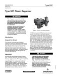
W4086-3
NPS 1, NPT
STEEL MAIN VALVE WITH TYPE 6492H PILOT
Product Description
The Type 92W pressure-reducing regulator for liquid
service includes either a Type 6492H or a Type 6492L
pilot (Figure 1). Both pilots have a friction-reducing
bellows seal on the stem. They offer precise
pressure-setting adjustment plus high sensitivity to
downstream pressure changes.
These pilots are available in either a standard version
with a drilled spring case vent, or an optional version
with a tapped spring case vent and a sealed adjusting
screw for pressure-loading service. A Fisher® 67 or
1301 Series regulator or a 670 Series panel-mounted
regulator may be used to load the pilot of a version for
pressure-loading service.
Specifications
Specifications for the Type 92W regulator are found in
the Specifications section.
W4088-1
NPS 3 (DN 80), FLANGED
CAST IRON MAIN VALVE WITH TYPE 6492L PILOT
Installation
Figure 1. Typical Connections
!
Warning
D101268X012
Personal injury, equipment damage,
or leakage due to escaping liquid
or bursting of pressure-containing
parts may result if this regulator is
overpressured or is installed where
service conditions could exceed the limits
given in the Specifications section and
on the appropriate nameplates, or where
conditions exceed any ratings of the
adjacent piping or piping connections.
www.emersonprocess.com/regulators
Type 92W
Specifications
Main Valve Body Sizes and End Connection Styles
BODY SIZE,
NPS (DN)
END CONNECTION STYLE AND RATING(1)
Cast Iron Body
Steel Body
1, 1-1/2, and 2
NPT
NPT
1, 1-1/2, 2, 2-1/2,
3, and 4
(25, 40, 50, 65,
80, and 100)
Flat-faced CL125B
or raised-faced
CL250B flanged
Raised-faced CL150,
CL300, or CL600 flanged
Maximum Inlet and Pilot Supply Pressure(1)
Cast Iron Main Valve and Pilot: 250 psig
(17,2 bar) or body rating limit, whichever is lower
Steel Main Valve and Pilot: 300 psig (20,7 bar)
or body rating limit, whichever is lower
Maximum Differential Pressure(1)
150 psig (10,3 bar) or body rating limit, whichever
is lower
Minumum Differential Pressure
20 psig (1,4 bar)
(1)
Outlet (Control) Pressure Ranges
See Table 1
Maximum Outlet Pressures(1)
See Table 2
Maximum Allowable Loading Pressure for Pilot with
Tapped Spring Case(1)
Combination of pilot control spring setting and spring
case loading pressure must not exceed 150 psig
(10,3 bar) for Type 6492H pilot or 25 psig (1,7 bar)
for Type 6492L pilot
Main Valve Port Diameters and Flow Coefficients
port diameter
body size,
NPS (DN)
Inches
mm
regulating
capacities
km
1 (25)
1-1/2 (40)
2 (50)
7/8
1-1/8
1-29/64
22,2
28,6
36,9
10
20
35
0.62
0.62
0.62
2-1/2 (65)
3 (80)
4 (100)
1-5/8
2-1/16
2-3/8
41,3
52,4
60,3
48
66
78
0.71
0.71
0.71
Maximum Material Temperature Capabilities(1)
Cast Iron Construction: 406°F (208°C)
Steel Construction: 500°F (260°C)
Pressure Registration
External through downstream control line
Downstream Control Line Connection
NPS 1, 1-1/2, or 2 (DN 25, 40, or 50) Body Size:
1/4 NPT female in main valve cylinder spacer
NPS 2-1/2, 3, or 4 (DN 65, 80, or 100) Body Size:
1/4 NPT female in pilot body
Pilot Spring Case Vent
1/8-inch (3,18 mm) drilled hole (standard pilot) or
1/4 NPT female tapping for pressure loading service
(optional pilot)
Approximate Weights
BODY SIZE,
NPS (DN)
1 (25)
1-1/2 (40)
2 (50)
2-1/2 (65)
3 (80)
4 (100)
END CONNECTION
APPROXIMATE WEIGHTS
Pounds
kg
NPT or flanged
NPT or flanged
32
44
14
20
NPT
Flanged
55
67
25
30
Flanged
Flanged
Flanged
90
115
165
41
52
75
1. The pressure/temperature limits in this Instruction Manual, or any applicable code or standard limitations, must not be exceeded.
To avoid such injury or damage, provide
pressure-relieving or pressure-limiting
devices to prevent service conditions from
exceeding those limits.
Additionally, the pilot could be broken
off the main valve by physical damage,
causing personal injury and property
damage due to escaping liquid. To avoid
such injury and damage, install the
regulator in a safe location where it is
protected from physical damage.
2
caution
Liquid pressure control systems should
be designed using good engineering
practices to eliminate quick starting or
stopping of the flow stream, which can
produce water hammer.
.
1. Only personnel qualified through training and
experience should install, operate, and maintain
a Type 92W regulator. Before installation, make
sure that there is no damage to, or debris in, the
regulator. Also make sure that all tubing and piping
are clean and unobstructed.
Type 92W
Table 1. Outlet (Control) Pressure Ranges
OUTLET (CONTROL) PRESSURE RANGES
Psig
PILOT CONTROL SPRING
COLOR CODE (SEE PARTS
LIST FOR PART NUMBER)
bar
Type 6492L Pilot
Type 6492H Pilot
Type 6492L Pilot
Type 6492H Pilot
2 to 6
5 to 15
13 to 25
10 to 30
25 to 75
70 to 150
0,14 to 0,41
0,34 to 1,0
0,90 to 1,7
0,69 to 2,1
1,7 to 5,2
4,8 to 10,3
Yellow
Green
Red
Table 2. Maximum Outlet Pressures
MAXIMUM OPERATING
OUTLET PRESSURE
CONSTRUCTION
MAXIMUM EMERGENCY OUTLET PRESSURE
(IF EXCEEDED, PRESSURE VESSEL INTEGRITY MAY NOT
BE RETAINED AND PERSONAL INJURY OR PROPERTY
DAMAGE COULD RESULT)
Cast Iron Main Valve
and Pilot Body
Steel Main Valve
and Pilot Body
With Type 6492H pilot
150 psig
(10,3 bar)
250 psig (17,2 bar) or main valve
body rating limit, whichever is lower
300 psig (20,7 bar) or main valve
body rating limit, whichever is lower
With Type 6492L pilot
25 psig
(1,7 bar)
50 psig (3,4 bar)
125 psig (8,6 bar)
2. A Type 92W regulator may be installed in any
orientation, as long as flow through the regulator
matches the direction of the arrow on the main
valve body.
3. Apply liquid-compatible pipe compound to the male
pipeline threads for an NPT body, or use suitable
line gaskets for a flanged body. Use acceptable piping
procedures when installing the regulator.
.
4. If continuous operation of the system is required during
inspection and maintenance, install a three-valve
bypass around the regulator. If the flowing medium
contains solids, install a properly sized strainer
upstream of the regulator.
Note
A regulator that has the Type 6492H or
6492L pilot with a 1/8-inch (3,2 mm) drilled
hole in the spring case may function
improperly if this spring case vent hole
becomes clogged. Install and maintain
such regulator so that the spring case vent
hole stays clear.
5. As shown in Figure 2, connect a control line as
large as possible but no smaller than 3/8-inch
(9,5 mm) diameter bushed down to the 1/4 NPT
connection in the cylinder spacer (NPS 1, 1-1/2,
or 2 body size) (DN 25, 40, or 50) or the pilot body
(NPS 2-1/2, 3, or 4 body size) (DN 65, 80, or 100).
With the NPS 2-1/2, 3, or 4 (DN 65, 80, or 100
body size, the pilot may be mounted as shown in
Figure 6 so that the control line connection faces
either upstream or downstream.
7. Do not locate the control line connection in a gate,
plug, or check valve; or in an elbow, swage, or
other area of the pipeline where turbulence or
abnormal velocities may occur; or in a large-volume
vessel that can cause noticeable control lag.
8. Install a shutoff valve (not a needle valve) in the control
line to isolate the pilot during maintenance.
9. Install a pressure gauge in the control line, or near the
regulator, to aid in setting the outlet pressure.
10. With a pressure-loaded or on-off pilot, connect
the pressure-loading or on-off piping or tubing to
the 1/4 NPT connection in the tapped pilot
spring case.
11. The pressure setting of the regulator is determined by:
• The pilot control spring adjustment on a standard
pilot, or .
• The pressure-loading device in conjunction with the
control spring adjustment on a pressure-loaded
pilot. In both cases, check these settings to make
sure they are correct for the application.
Startup and Adjustment
Note
The maximum inlet pressure for a specific
construction is stamped on the main
valve nameplate. Use pressure gauges
to monitor upstream and downstream
pressures during startup.
.
6. Locate the control line connection at least 10 pipe
diameters away from the regulator or swage and in a
section of straight pipe.
.
3
Type 92W
air
loading
regulator
control line
connection
needle
valve
control line
shutoff valve
bleed restriction (required only
if the loading regulator does
not have internal relief)
control line
connection
control line
shut off valve
strainer
strainer
block
valves
block
valve
vent valve
block
valves
bypass line
block
valve
vent valve
bypass line
16A7958-B
A2607-1
16A7958-B
16A1547-A
A3334
with standard pilot
WITH PRESSURE-LOADED PILOT
Figure 2. Typical Installations
Adjustment
On a regulator with a standard or pressure-loaded
Type 6492H or 6492L pilot, loosen the hex nut
(key 16, Figure 4). Turn the adjusting screw (key 15,
Figure 4) into the spring case to increase the downstream
pressure. Turn the adjusting screw out of the spring
case to decrease the downstream pressure. When
the required downstream pressure is maintained
for several minutes, tighten the hex nut to lock the
adjusting screw in position.
On a regulator with a pressure-loaded Type 6492H
or 6492L pilot, also refer to the instruction manual of
the pressure-loading device for downstream pressure
adjustment procedures. Make sure that the combined pilot
control spring setting pressure and spring case loading
pressure does not exceed 150 psig (10,3 bar) for the
Type 6492H pilot or 25 psig (1,7 bar) for the Type 6492L
pilot. For example, combining a 5 psig (0,34 bar) spring
setting pressure and a 10 psig (0,69 bar) spring case loading
pressure results in a regulator pressure of 15 psig (1,0 bar).
Startup with New Regulator Installation
1. Remove all pilot control spring compression by turning
the adjusting screw out of the spring case according to
the adjustment procedure.
2. Slowly open the upstream block valve.
4. Open the control line shutoff valve.
.
6. Perform the adjustment procedure until the downstream
pressure reaches the desired setting.
4
1. Open the upstream and downstream block valves and
let the regulator take over control at the existing pilot
control spring setting.
.
2. If a bypass line is used, slowly control the bypass line
block valve.
.
Shutdown
1. If a bypass line is used, slowly open the bypass line
block valve while monitoring the downstream pressure.
2. Close the control line shutoff valve.
3. Close the downstream block valve.
4. Close the upstream block valve.
5. If a pressure-loaded or on-off pilot is used, close the
needle valve to the pilot.
.
6. Vent the regulator and control line to release any
trapped pressure.
Principle of Operation
Pilot supply pressure is piped from the main valve inlet
(Figure 3) to the pilot inlet connection. Downstream
pressure registers on the main valve pistons through the
downstream control line and then on the pilot diaphragm.
3. Open the downstream block valve.
5. If a bypass is used, slowly close the bypass line
block valve.
Startup with Existing Regulator
Installation After Normal Shutdown
When increased downstream demand lowers the
downstream pressure to a value below the setting of the
pilot control spring, this spring forces the pilot valve plug
open to increase the loading pressure on the main valve
Type 92W
Type 92S
August 2007
Type 92S Self-Powered Control Valve
Type 92S
September 2006
A6553
Type 92S 2-1/2 thru 6 x 4-Inch (DN 65 thru 150 x 100)
inlet pressure
inlet pressure
OUTLET pressure
OUTLET pressure
ATMOSPHERIC pressure
ATMOSPHERIC pressure
LOADING pressure
LOADING pressure
A6552
A6553
Type 92W with Type 6492L Pilot
NPS 1 THROUGH 2 (DN 25 THROUGH 50) MAIN VALVE
Type 92W with Type 6492H Pilot
NPS 2-1/2 THROUGH 6 X 4 (DN 65 THROUGH 150 X 100) MAIN VALVE
Figure 3. Operational Schematics
pistons. At the same time, the increased demand lowers
the downstream pressure on the main valve piston(s).
This opens the main valve plug, increasing flow to the
downstream system to satisfy the increased demand and
to restore downstream pressure to the setting of the pilot
control spring.
Decreased downstream demand increases the downstream
pressure registered on the pilot diaphragm. The increased
pressure overcomes the force of the pilot control spring
and allows the pilot valve plug spring to close the pilot
valve plug. As the pilot valve plug closes, excess loading
pressure bleeds to the downstream system through the pilot
bleed restriction. At the same time, decreased downstream
demand increases the downstream pressure registered
on the main valve piston(s). This allows the main valve
spring to close the main valve plug, reducing flow to the
downstream system in response to the decreased demand.
With a pressure-loaded or on-off pilot, the operation is the
same as for a standard pilot except that the pilot control
spring force on the pilot valve plug is aided by pneumatic
pressure from the loading device or solenoid valve.
Maintenance
Regulator parts are subject to normal wear and must be
inspected periodically and replaced as necessary. The
frequency of inspection and replacement depends upon
the severity of service conditions and upon applicable
codes and government regulations.
!
Warning
Avoid personal injury or damage to
property from sudden release of pressure
or uncontrolled process fluid. Before
starting to disassemble:
• Isolate the regulator from the process,
• Release process pressure, and
.
• Vent the pilot supply and main valve
loading pressures.
.
Types 6492H and 6492L Pilots
These procedures are to be performed if inspecting,
cleaning, or replacing any pilot parts, or if cycling, erratic
control, or too high or too low an outlet (control) pressure
is noted. Perform only those procedures in this section
required to correct the problem. Key numbers refer to
Figure 4 unless otherwise noted.
Note
Before performing any maintenance,
loosen the hex nut (key 16), if used,
and turn the adjusting screw (key 15)
counterclockwise until all compression is
removed from the control spring (key 12).
Remove the pilot from the pipe nipple and
connectors (keys 82 and 83, Figure 6).
.
5
Type 92W
1. Unscrew the plug guide (key 2). Remove the screen
(key 77), plug (key 4), plug spring (key 3), and stem
(key 7). Unscrew the seat ring (key 5). Examine the
seat ring and plug seating surfaces for damage.
2. Clean and replace parts as necessary. Apply Led-Plate
Number 250(1) sealant or equivalent to the seat ring
threads. Thread the seat ring into place and tighten it
to between 19 and 25 foot-pounds (26 and 34 N•m)
of torque.
3. Handle the parts carefully, and place the plug spring
(key 3) in the plug guide (key 2). Slide the plug (key 4)
over the spring and into the plug guide. Place the
screen (key 77) onto the plug guide. Place the stem
(key 7) in the center hole of the plug guide. Apply
Led-Plate Number 250 sealant or equivalent to the plug
guide threads, and screw the guide plus attached parts
into the body (key 1).
4. Remove the pipe plug and bleed restriction (keys 74 and
76). Clean or replace the restriction as necessary.
5. Sparingly apply Led-Plate Number 250 sealant or
equivalent to the threads of the restriction, and thread
the restriction into place.
6. Apply Led-Plate Number 250 sealant or equivalent to the
threads of the pipe plug. Thread the pipe plug into place
and tighten it to between 5 and 15 foot-pounds (7,0 and
20 N•m) of torque.
7. Remove the cap screws (key 17), spring case (key 14),
control spring (key 12), and upper spring seat (key 13)
from the body.
8. Remove the lower spring seat (key 11, Type 6492H
pilot only) or diaphragm assembly (key 24, Type 6492L
pilot only), diaphragms (key 10), and diaphragm gasket
(key 18) from the body. Inspect and clean the
diaphragm gasket, and replace it if necessary.
9. Unscrew the bellows retainer (key 8) and remove the
bellows (key 9). Replace worn parts as necessary, and
install the bellows and bellows retainer. Tighten the
bellows retainer to between 19 and 25 foot-pounds (26
and 34 N•m).
10. Install the diaphragm gasket. Install both diaphragms
with their raised preformed centers facing toward the
spring case.
11. Lubricate the upper spring seat and the exposed
threads of the adjusting screw with Never-Seez(2)
lubricant or equivalent. Install the lower spring seat
(key 11, Type 6492H pilot only) or diaphragm assembly
(key 24, Type 6492L pilot only), control spring
(key 12), upper spring seat (key 13), and spring case
(key 14). Insert and tighten the cap screws (key 17)
to between 12 and 18 foot-pounds (16,0 and
24,00 N•m) of torque, using a crisscross bolting pattern.
1. Trademark of Armite Laboratories.
2. Trademark of Never-Seez Corp.
6
12. When pilot maintenance is complete, refer to the
startup and adjustment procedure to put the regulator
back in operation and adjust the pressure setting.
Type 92W Main Valve
Perform these procedures if replacing the piston(s),
cylinder(s), stem(s), seals, valve plug, or seat ring. All
key numbers are referenced in Figure 5 except where
otherwise indicated. Instructions are given for complete
disassembly and assembly. Disassemble the main
valve only as far as necessary to complete the required
maintenance. Then, begin the assembly procedure at the
appropriate step. .
Note
The regulator may remain in the pipeline
during maintenance procedures unless the
main valve body is replaced or removed
for repairs.
.
Whenever a gasket seal is disturbed by
removing or shifting gasketed parts, a
new gasket should be installed upon
reassembly. This is necessary to ensure a
good gasket seal.
.
Disassembly
1. Disconnect all tubing and remove the pilot from the
main valve.
.
2. Remove the cap screws (key 3, not shown) from a cast
iron body, or stud nuts (key 4) from a steel body, and lift
off the body flange.
3. For the NPS 1, 1-1/2, and 2 sizes (DN 25, 40, and 50),
remove the top cylinder (key 17), and pull out the top
piston with attached stem and other parts. Remove
the hex nut (key 41), lock washer (key 40), top ring
retainer (key 26), and top piston ring (key 25) from the
top piston (key 24).
4. For the NPS 1, 1-1/2, and 2 sizes (DN 25, 40, and 50),
lift off the cylinder spacer (key 21), and remove the
stem seal retainer (key 23) and stem seal (key 22) from
the spacer.
5. Remove the cylinder (key 17), piston (key 24) with
attached parts, and spiral wound gasket (key 8).
6. Remove the cotter pin (key 16, NPS 1, 1-1/2, and 2
sizes only) (DN 25, 40, and 50), stem nut (key 15),
bottom stem (key 9) with hex head, valve plug (key 6),
piston ring retainer (key 26), piston ring (key 25), bottom
piston ring retainer (key 26, NPS 1, 1-1/2, and 2
sizes only) (DN 25, 40, and 50), piston (key 24), spring
(key 12), piston spacer (key 11), cage (key 5), and seat
ring (key 7).
Type 92W
7. Either remove the retaining ring (key 14), or, if it is
necessary to remove the baffle (key 13), remove the
spring seat, washer, and O-ring (keys 32, 34, and 38).
With an NPS 2-1/2 through 4 (DN 65 through 100) sizes
only, also remove the plug spacer (key 33).
Assembly
1. Inspect and replace parts as necessary, making
sure that the hollow passage in the top stem (NPS 1,
1-1/2, and 2 sizes only) (DN 25, 40, and 50) is free
from debris.
2. Install a spiral wound gasket (key 8) into the
body (key 1).
3. If installing a new valve plug and/or a new seat ring,
lap the seating surfaces together outside the body. Use
a commercial lapping compound or a mixture of
solidified vegetable oil and 600-grit or finer silicon
carbide or aluminum oxide.
4. Install the baffle (key 13), plug spacer (key 33) if used,
and either the retaining ring (key 14) or the O-ring,
washer, and spring seat (keys 38, 34, and 32), and then
install the seat ring (key 7), valve plug (key 6), and stem
(key 9) into the cage (key 5). Then, install the piston
spacer (key 11) down through the baffle until it contacts
the valve plug. Install the spring (key 12), and secure
with the piston (key 24), piston ring (key 25) with its open
end pointing out, piston ring retainer (key 26), and stem
nut (key 15).
For the NPS 1, 1-1/2, and 2 sizes (DN 25, 40, and 50),
lock the stem nut in place with a cotter pin (key 16), but
do not fold the pin ends up on top of the stem since this
can interfere with loading pressure registration through
the top stem passage.
5. Install the main piston cage assembly with attached
parts into the body. Coat one of the serrated edges
of the main cylinder (key 17) with Led-Plate Number 250
sealant or equivalent, install a new cylinder gasket
(key 18) onto this edge, and install the cylinder gasketside-up on the cage.
6. Install a new body gasket (key 19) onto the appropriate
edge of the body.
7. For NPS 1, 1-1/2, and 2 sizes (DN 25, 40, and 50),
install the stem seal (key 22) onto the cylinder spacer
(key 21) in the orientation shown in Figure 5, and secure
with the stem seal retainer (key 23). Coat the serrated
edge of the spacer with Led-Plate Number 250 sealant
or equivalent, and install the spacer edge-side-down
over the bottom cylinder.
8. For NPS 1, 1-1/2, and 2 sizes (DN 25, 40, and 50),
install the top piston ring (key 25) with its open end
pointing out, ring retainer (key 26), and stem (key 20) on
the top piston. Secure these parts with the lock washer
and hex nut (keys 40 and 41). Install the top piston plus
attached parts stem-first through the stem seal until the
top stem contacts the bottom stem.
.
9. For NPS 1, 1-1/2, and 2 sizes (DN 25, 40, and 50), coat
both serrated edges of the top cylinder (key 17) with
Led-Plate Number 250 sealant or equivalent, install
new cylinder gaskets (key 18) on these edges, and
install the cylinder down over the top piston into the
cylinder spacer.
10. Install the body flange (key 2) on the body, and secure
with the cap screws (key 3, not shown) for a cast iron
body or with the stud nuts (key 4) for a steel body.
11. Install the pilot and connect all tubing as shown
in Figure 6.
.
12. When all maintenance is complete, refer to the startup
and adjustment procedure to put the regulator back into
operation and adjust the pressure setting.
Parts Ordering
When corresponding with a local Sales Office about
this equipment, always reference the equipment serial
number as found on the regulator nameplates.
When ordering replacement parts, reference the
complete 11-character part number of each needed part
as found in the following parts list.
Parts List
Types 6492L and 6492H Pilots (Figure 4)
Key
Description
Repair Kits (included are keys 4, 5, 7
8, 9, 10, and 18)
Type 6492L pilot
Type 6492H pilot
1
Body
Cast Iron
Type 6492L pilot
Type 6492H pilot
Steel
Type 6492L pilot
Type 6492H pilot
2
Plug Guide, Stainless steel
3
Plug Spring, 302 Stainless steel
4*
Plug, 302 Stainless steel
5*
Seat Ring, 416 Stainless steel
7*
Stem, 416 Stainless steel
8*
Bellows Retainer, Brass
9*
Bellows, Brass
10* Diaphragm, 302 Stainless steel (2 required)
Type 6492L pilot
Type 6492H pilot
Part Number
R6492LX0012
R6492HX0012
32A0404X012
22A0403X012
32A0404X052
22A0403X052
1E391835132
1E392437022
1F967446172
1H564446172
1F967835132
1F971214012
1F971318992
1E396936012
1E395836012
*Recommended spare part.
7
Type 92W
Key
Description
11 Lower Spring Seat, Aluminum
(Type 6492H pilot only)
12 Control Spring, Steel, Cadmium Plate
(see Table 1 for outlet pressure ranges)
Yellow color code
Green color code
Red color code
13 Upper Spring Seat Steel, Cadmium Plate
14 Spring Case
Standard cast iron
Type 6492L pilot
Type 6492H pilot
Tapped cast iron
Type 6492L pilot
Type 6492H pilot
Standard steel
Type 6492L pilot
Type 6492H pilot
Tapped steel
Type 6492L pilot
Type 6492H pilot
15 Adjusting Screw (standard spring
case only) steel, Cadmium Plate
16 Hex Nut (standard spring case only),
steel, Cadmium Plate
17 Cap Screw, steel, plate (10 required for
Type 6492L pilot and 8 required for
Type 6492H pilot)
18* Diaphragm Gasket, Encapsulated
Fiber Asbestos
Type 6492L pilot
Type 6492H pilot
19 Drive Screw, SST (2 required)
20 Nameplate, Aluminum
24 Diaphragm Plate Assembly,
Aluminum/Steel/Stainless steel
(Type 6492L pilot only)
74 Pipe Plug, Steel
76 Bleed Restriction, 304 Stainless steel
77 Screen, 304 Stainless steel
78 Reducing Bushing, Carbon steel
79 Never-Seez Lubricant, 1 gallon (3,8 L)
can (not furnished)
80 Led-Plate No. 250 Sealant, 5 pounds
(2 kg) can (not furnished)
87 Sealing Washer, Carbon steel
(tapped spring case only)
Part Number
1E395408012
1E395627022
1D745527142
1E395727192
1D667125072
3J496319012
2J496219012
3L442119012
2L441919012
3L416122012
2L416322012
3L442222012
2L442022012
1D995448702
1A353724122
1A381624052
1E397004022
1E396104022
1A368228982
19A3510X0A2
1E3967X0012
0Z020128992
19A2612X012
16A1512X012
1C379026232
1M523906992
1M524006992
1V205699012
Type 92W Main Valve (Figure 5)
Repair Kits (included are keys 8, 16,
18, 19, 25, and 38)
NPS 1 (DN 25) body
NPS 1-1/2 (DN 40) body
NPS 2 (DN 50) body
NPS 2-1/2 (DN 65) body
NPS 3 (DN 80) body
NPS 4 (DN 100) body
1
Body
2
Body Flange
Cast iron
NPS 1 (DN 25) body
NPS 1-1/2 (DN 40) body
NPS 2 (DN 50) body
NPS 2-1/2 (DN 65) body
NPS 3 (DN 80) body
NPS 4 (DN 100) body
WCC steel
NPS 1 (DN 25) body
NPS 1-1/2 (DN 40) body
*Recommended spare part.
8
R92SX000052
R92SX000062
R92SX000072
R92EX0000B2
R92EX000032
R92EX000042
See following Table
26A7837X012
26A7900X012
26A7869X012
27A1548X012
27A1576X012
27A1600X012
26A7838X012
26A7901X012
Key
Description
Part Number
2
Body Flange
WCC steel (continued) NPS 2 (DN 50) body
26A7870X012
NPS 2-1/2 (DN 65) body
27A1549X012
NPS 3 (DN 80) body
27A1577X012
NPS 4 (DN 100) body
27A1601X012
3
Cap Screw (not shown), Plate steel
(for cast iron body)
NPS 1 (DN 25) body (4 required)
16A7839X012
NPS 1-1/2 or 2 (DN 40 or 50)
body (8 required)
1U625631192
NPS 2-1/2 (DN 65) body (8 required)
1R281124052
NPS 3 (DN 80) body (8 required)
1A454124052
NPS 4 (DN 100) body (8 required)
1A440224052
3
Stud Bolt, B7 Steel (for steel body)
NPS 1 (DN 25) body (4 required)
1V5426X0012
NPS 1-1/2 or 2 body (DN 40 or 50)
(8 required)
16A7902X012
NPS 2-1/2 (DN 65) body (8 required)
1R284831012
NPS 3 (DN 80) body (8 required)
1A378131012
NPS 4 (DN 100) body (8 required)
1R369031012
4
Stud Nut, Steel (for steel body)
NPS 1 (DN 25) body (4 required)
1C330624072
NPS 1-1/2 or 2 (DN 40 or 50) body
(8 required)
1A377224072
NPS 2-1/2 (DN 65) body (8 required)
1C330624072
NPS 3 (DN 80) body (8 required)
1A376024072
NPS 4 (DN 100) body (8 required)
1A352024072
5
Cage, Cast Iron
NPS 1 (DN 25) body
29A1379X012
NPS 1-1/2 (DN 40) body
26A7903X012
NPS 2 (DN 50) body
26A7872X012
NPS 2-1/2 (DN 65) body
27A1550X012
NPS 3 (DN 80) body
27A1578X012
NPS 4 (DN 100) body
27A1602X012
6
Valve Plug, 17-4PH Stainless steel
NPS 1 (DN 25) body
16A7842X012
NPS 1-1/2 (DN 40) body
16A7904X012
NPS 2 (DN 50) body
16A7873X012
NPS 2-1/2 (DN 65) body
27A1552X012
NPS 3 (DN 80) body
27A1580X012
NPS 4 (DN 100) body
27A1604X012
7
Seat Ring, 416 Stainless steel
NPS 1 (DN 25) body
16A7844X012
NPS 1-1/2 (DN 40) body
16A7906X012
NPS 2 (DN 50) body
16A7875X012
NPS 2-1/2 (DN 65) body
27A1553X012
NPS 3 (DN 80) body
27A1581X012
NPS 4 (DN 100) body
27A1605X012
8*
Spiral Wound Gasket,
316L Stainless steel and Graphite
NPS 1 (DN 25) body
16A7845X012
NPS 1-1/2 (DN 40) body
16A7907X012
NPS 2 (DN 50) body
16A7876X012
NPS 2-1/2 (DN 65) body
17A1554X012
NPS 3 (DN 80) body
17A1582X012
NPS 4 (DN 100) body
17A1606X012
9
Bottom Stem, Plate steel
NPS 1 (DN 25) body
16A7846X012
NPS 1-1/2 (DN 40) body
16A7908X012
NPS 2 (DN 50) body
16A7877X012
NPS 2-1/2 (DN 65) body
17A1556X012
NPS 3 (DN 80) body
17A1584X012
NPS 4 (DN 100) body
17A1608X012
11 Piston Spacer, Steel
NPS 1 (DN 25) body
16A7848X012
NPS 1-1/2 (DN 40) body
16A7910X012
NPS 2 (DN 50) body
16A7879X012
NPS 2-1/2 (DN 65) body
17A1558X012
NPS 3 (DN 80) body
17A1585X012
NPS 4 (DN 100) body
17A1610X012
Type 92W
Key 1 Body
Key
body
material
end
connection
style
1 (25)
1-1/2 (40)
2 (50)
2-1/2 (65)
3 (80)
4 (100)
Cast iron
NPT
CL125 FF
CL250 RF
26A7830X012
26A7831X012
26A7832X012
26A7893X012
26A7894X012
26A7895X012
26A7862X012
26A7863X012
26A7864X012
---37A1543X012
37A1544X012
---37A1571X012
37A1572X012
---37A1595X012
37A1596X012
WCC steel
NPT
CL150 RF
CL300 RF
CL600 RF
26A7833X012
26A7834X012
26A7835X012
26A7836X012
26A7896X012
26A7897X012
26A7898X012
26A7899X012
26A7865X012
26A7866X012
26A7867X012
26A7868X012
---37A1545X012
37A1546X012
37A1547X012
---37A1573X012
37A1574X012
37A1575X012
---37A1597X012
37A1598X012
37A1599X012
Part Number
Key
body size, NPS (DN)
Description
12 Spring, Spring Wire
NPS 1 (DN 25) body
NPS 1-1/2 (DN 40) body
NPS 2 (DN 50) body
NPS 2-1/2 (DN 65) body
NPS 3 (DN 80) body
NPS 4 (DN 100) body
13 Baffle, Stainless steel
NPS 1 (DN 25) body
NPS 1-1/2 (DN 40) body
NPS 2 (DN 50) body
NPS 2-1/2 (DN 65) body
NPS 3 (DN 80) body
NPS 4 (DN 100) body
14 Retaining Ring, Steel
NPS 1 (DN 25) body
NPS 1-1/2 (DN 40) body
NPS 2 (DN 50) body
15 Stem Nut, Steel
NPS 1 (DN 25) body
NPS 1-1/2 or 2 (DN 40 or 50) body
NPS 2-1/2 or 3 (DN 65 or 80) body
NPS 4 (DN 100) body
16 Cotter Pin, Stainless steel
NPS 1 (DN 25) body
NPS 1-1/2 or 2 (DN 40 or 50) body
17 Cylinder, 416 Stainless steel
NPS 1 (DN 25) body (2 required)
NPS 1-1/2 body (DN 40) (2 required)
NPS 2 (DN 50) body (2 required)
NPS 2-1/2 (DN 65) body (1 required)
NPS 3 (DN 80) body (1 required)
NPS 4 (DN 100) body (1 required)
18* Cylinder Gasket, Copper
NPS 1 (DN 25) body (3 required)
NPS 1-1/2 (DN 40) body (3 required)
NPS 2 (DN 50) body (3 required)
NPS 2-1/2 (DN 65) body (1 required)
NPS 3 (DN 80) body (1 required)
NPS 4 (DN 100) body (1 required)
19* Body Gasket, Copper
NPS 1 (DN 25) body
NPS 1-1/2 (DN 40) body
NPS 2 (DN 50) body
NPS 2-1/2 (DN 65) body
NPS 3 (DN 80) body
NPS 4 (DN 100) body
20 Top Stem, Stainless steel
NPS 1 (DN 25) body
NPS 1-1/2 or 2 (DN 40 or 50) body
21 Cylinder Spacer, Steel
NPS 1 (DN 25) body
NPS 1-1/2 (DN 40) body
NPS 2 (DN 50) body
22 Stem Seal, Polytetrafluoroethylene (PTFE)/glass
NPS 1 (DN 25) body
NPS 1-1/2 or 2 (DN 40 or 50) body
16A7849X012
16A7911X012
16A7880X012
17A1559X012
17A1586X012
17A1611X012
19A1378X012
16A7912X012
16A7881X012
17A1560X012
17A1587X012
17A1612X012
16A7851X012
16A7913X012
16A7882X012
16A7852X012
16A7914X012
1A413224122
1A420124122
16A7930X012
17A5574X012
16A7853X012
16A7915X012
16A7884X012
17A1561X012
17A1588X012
17A1613X012
16A7854X012
16A7916X012
16A7885X012
14A5685X022
17A1589X012
17A1614X012
14A6785X022
14A3384X022
14A5685X022
17A1563X012
13A0354X022
14A5650X022
16A7855X012
16A7886X012
26A7856X012
26A7918X012
26A7887X012
16A7962X012
16A7963X012
Description
23 Stem Seal Retainer, Stainless steel
NPS 1 (DN 25) body
NPS 1-1/2 or 2 (DN 40 or 50) body
24 Piston, 416 Stainless steel
NPS 1 (DN 25) body (2 required)
NPS 1-1/2 (DN 40) body (2 required)
NPS 2 (DN 50) body (2 required)
NPS 2-1/2 (DN 65) body (1 required)
NPS 3 (DN 80) body (1 required)
NPS 4 (DN 100) body (1 required)
25 Piston Ring, PTFE
NPS 1 (DN 25) body (2 required)
NPS 1-1/2 (DN 40) body (2 required)
NPS 2 (DN 50) body (2 required)
NPS 2-1/2 (DN 65) body (1 required)
NPS 3 (DN 80) body (1 required)
NPS 4 (DN 100) body (1 required)
26 Ring Retainer, 302 Stainless steel
NPS 1 (DN 25) body (2 required)
NPS 1-1/2 (DN 40) body (2 required)
NPS 2 (DN 50) body (2 required)
NPS 2-1/2 (DN 65) body (1 required)
NPS 3 (DN 80) body (1 required)
NPS 4 (DN 100) body (1 required)
28 Nameplate, Stainless steel
29 Flow Arrow, Stainless steel
NPS 1 (DN 25) body
NPS 1-1/2, 2, 2-1/2, 3, or 4
(DN 40, 50, 65, 80, or 100) body
30 Drive Screw, Stainless steel (4 required)
31 Led-Plate Number 250 Sealant,
5 pounds (2 kg) can (not furnished
with regulator)
32 Spring Seat, Carbon steel
NPS 2-1/2 (DN 65) body
NPS 3 (DN 80) body
NPS 4 (DN 100) body
33 Plug Spacer, steel
NPS 2-1/2 (DN 65) body
NPS 3 (DN 80) body
NPS 4 (DN 100) body
34 Washer, Carbon steel
NPS 2-1/2 or 3 (DN 65 or 80) body
NPS 4 (DN 100) body
35 Groove Pin, Stainless steel
NPS 2-1/2 (DN 65) or larger body
38* O-Ring, PTFE
NPS 2-1/2 or 3 (DN 65 or 80) body
NPS 4 (DN 100) body
40 Lockwasher, Stainless steel
NPS 1 (DN 25) body
NPS 1-1/2 or 2 (DN 40 or 50) body
41 Hex Nut
NPS 1 (DN 25) body, 316 Stainless steel
NPS 1-1/2 or 2 (DN 40 or 50) body,
Zinc-plated steel
Part Number
16A7857X012
16A7888X012
19A6005X012
19A6006X012
19A6007X012
17A1564X012
17A1590X012
17A1615X012
19A6010X012
19A6011X012
19A6012X012
17A1565X012
17A1591X012
17A1616X012
16A7860X012
16A7922X012
16A7891X012
17A1566X012
17A1592X012
17A1617X012
16A7917X0A2
1V105938982
1V106038982
1A368228982
1M524006992
17A1567X012
17A1593X012
17A1618X012
17A1568X012
17A1594X012
17A1619X012
17A1569X012
17A1620X012
1C8989X0012
17A7396X012
17A7397X012
1F128035022
1A505638992
1A391535252
1A346524122
*Recommended spare part.
9
Type 92W
15
15
13
12
11
10
18
5
77
11
13
16
14
9
10
8
18
7
12
9
20 8
19 7
5
17
77
76 4
4
3
39A3514-B
apply lub/sealant
2
74 3
2
16
14
87
20
15
16
19
17
76
1
74
78
1
78
2
32A4712-A
A3505
detail of tapped
spring case with sealed
adjusting screw
39A3514-B
apply lub/sealant
complete type 6492h pilot
15
13
12
24
9
10
8
18
7
1
5
4
77
3
2
39A3515-B
apply lub/sealant
16
14
20
19
17
76
74
78
complete type 6492l pilot
Figure 4. Pilot Assemblies
Pilot Mounting Parts (Figure 6)
Key
Description
81 Loading Tubing, Copper
82 Pipe Nipple, Steel
83 Connector, Brass
84 Elbow, brass (3 required for NPS 1, 1-1/2,
or 2 body size and 1 required for larger
sizes) (DN 25, 40, or 50)
10
Part Number
0500201701W
1U264426232
15A6002X202
15A6002X162
Key
Description
85 Inlet Tubing, copper (NPS 1, 1-1/2, or
2 body only) (DN 25, 40, or 50)
86 Elbow, carbon steel (NPS 2-1/2 through 4 body
only) (DN 65 thru 100)
Part Number
0500201701W
1B8608X0012
Type 92W
30
29
41
3
18
28
2
40
25
20
21
18
22
16
19
14
15
13
5
11
7
31
8
9
6
1
26
31
23
31
24
4
30
17
31
12
apply sealant
NPS 1, 1-1/2, or 2 (dn 25, 40, or 50) body size
30
29
26
41
3
18
28
2
36A7960-D
25
31
37A1622-D
23
22
3
15
19
28
25
15
11
5
12
17
7
34
5
8
13
32
6
33
24
20
CORRECT ORIENTATION OF PISTON RING (KEY 25)
2
24
38
40
21
26
18
25
7
8
35
6
9
1
18
4
30
19
31
16
14
4
30
17
12
13
11
9
1
31
NPS 2-1/2, 3, or 4 (dn 65, 80, or 100) body size
Figure 5. Type 92W Main Valve Assemblies
11
Type 92W
81
84
85
82
83
29A3518-B
NPS 1, 1-1/2, or 2 (dn 25, 40, or 50) body size
83
81
SUPPLY
CONTROL
39A3519-C
83
82
CONTROL
86
LOADING
84
81
30B3840-A
with pilot mounted in standard position so control
line connection faces downstream
81
SUPPLY
86
84
LOADING
with pilot mounted in optional position so control
line connection faces upstream
NPS 2-1/2, 3, or 4 (DN 65, 80, or 100) body size
Figure 6. Pilot Mounting Parts
Industrial Regulators
Natural Gas Technologies
TESCOM
Emerson Process Management
Regulator Technologies, Inc.
Emerson Process Management
Regulator Technologies, Inc.
Emerson Process Management
Tescom Corporation
USA - Headquarters
McKinney, Texas 75069-1872 USA
Tel: 1-800-558-5853
Outside U.S. 1-972-548-3574
USA - Headquarters
McKinney, Texas 75069-1872 USA
Tel: 1-800-558-5853
Outside U.S. 1-972-548-3574
USA - Headquarters
Elk River, Minnesota 55330-2445 USA
Tel: 1-763-241-3238
Asia-Pacific
Shanghai, China 201206
Tel: +86 21 2892 9000
Asia-Pacific
Singapore, Singapore 128461
Tel: +65 6777 8211
Europe
Bologna, Italy 40013
Tel: +39 051 4190611
Europe
Bologna, Italy 40013
Tel: +39 051 4190611
Gallardon, France 28320
Tel: +33 (0)2 37 33 47 00
Middle East and Africa
Dubai, United Arab Emirates
Tel: +971 4811 8100
Europe
Selmsdorf, Germany 23923
Tel: +49 (0) 38823 31 0
For further information visit www.emersonprocess.com/regulators
The Emerson logo is a trademark and service mark of Emerson Electric Co. All other marks are the property of their prospective owners. Fisher is a mark owned by Fisher Controls, Inc., a
business of Emerson Process Management.
The contents of this publication are presented for informational purposes only, and while every effort has been made to ensure their accuracy, they are not to be construed as warranties or
guarantees, express or implied, regarding the products or services described herein or their use or applicability. We reserve the right to modify or improve the designs or specifications of such
products at any time without notice.
Emerson Process Management does not assume responsibility for the selection, use or maintenance of any product. Responsibility for proper selection, use and maintenance of any Emerson
Process Management product remains solely with the purchaser.
©Emerson Process Management Regulator Technologies, Inc., 2004, 2009; All Rights Reserved