1
Bulletin 71.2:92B
Table 1. Body Sizes and End Connection Styles
END CONNECTION STYLES
BODY SIZES, NPS / DN
1 / 25
Cast iron Body
NPT
1-1/2 and 2 / 40 and 50
NPT, CL125 FF and CL250 RF
NPT, SWE(1), CL150 RF, CL300 RF
and PN 16/25/40 RF
Steel and Stainless steel Body
3 and 4 / 80 and 100
CL125 FF and CL250 RF
CL150 RF, CL300 RF, PN 16 RF and PN 25/40 RF
1. Available in steel bodies only.
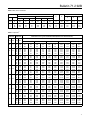
Table 2. Outlet Pressure Ranges
PILOT TYPE
OUTLET PRESSURE
SPRING WIRE DIAMETER
SPRING FREE LENGTH
PART NUMBER
COLOR CODE
63.5
66.5
62.0
1E395627022
1D7455T0012
1E395727192
Yellow
Green
Black
2.50
2.62
2.44
63.5
66.5
62.0
1E395627022
1D7455T0012
1E395727192
Yellow
Green
Black
2.50
2.50
63.5
63.5
14B9943X012
14B9942X022
Unpainted
Unpainted
psig
bar
In.
mm
In.
mm
Low-Pressure
2 to 6
5 to 15
13 to 25
0.14 to 0.41
0.34 to 1.0
0.90 to 1.7
0.207
0.234
0.283
5.26
5.94
7.19
2.50
2.62
2.44
High-Pressure
15 to 30
25 to 75
70 to 150
1.0 to 2.1
1.7 to 5.2
4.8 to 10.3
0.207
0.234
0.281
5.26
5.94
7.14
High Temperature
15 to 100
80 to 250
1.0 to 6.9
5.5 to 17.2
0.282
0.375
7.16
9.53
Table 3. Maximum Inlet Pressures and Temperatures
BODY MATERIAL
MAXIMUM
TEMPERATURE
psig
bar
°F
°C
NPT
250
17.2
406
208
CL125 FF
125
8.6
353
178
CL250 RF
250
17.2
406
208
NPT
300
20.7
450
232
SWE
300
20.7
450
232
CL150 RF
185
12.8
450
232
CL300 RF
300
20.7
600
316(1)
PN 16/25/40 RF (NPS 1, 1-1/2, 2 and 3 / DN 25, 40, 50 and 80)
300
20.7
600
316(1)
PN 16 RF (NPS 4 / DN 100)
185
12.8
450
232
PN 25/40 RF (NPS 4 / DN 100)
300
20.7
600
316(1)
232
Cast iron
Steel
Stainless steel
MAXIMUM INLET PRESSURE
END CONNECTION
NPT
300
20.7
450
CL150 RF
175
12.1
450
232
CL300 RF
300
20.7
600
316(1)
PN 16/25/40 RF (NPS 1, 1-1/2, 2 and 3 / DN 25, 40, 50 and 80)
300
20.7
600
316(1)
PN 16 RF (NPS 4 / DN 100)
175
12.1
450
232
PN 25/40 RF (NPS 4 / DN 100)
300
20.7
600
316(1)
1. 450°F / 232°C with standard seat ring, 600°F / 316°C with seal weld option.
Table 4. Minimum Differential Pressures for Safety Override System
TYPE
6492HM
6492HTM
SPRING RANGE
SPRING COLOR
MINIMUM PRESSURE AT WHICH
MONITORING PILOT CAN BE SET
psig
bar
10 to 30
0.69 to 2.1
Yellow
10 psig / 0.69 bar over normal downstream pressure
25 to 75
1.7 to 5.2
Green
10 psig / 0.69 bar over normal downstream pressure
70 to 150
4.8 to 10.3
Black
15 psig / 1.0 bar over normal downstream pressure
15 to 100
1.0 to 6.9
Unpainted
10 psig / 0.69 bar over normal downstream pressure
80 to 250
5.5 to 17.2
Unpainted
25 psig / 1.7 bar over normal downstream pressure
5