1
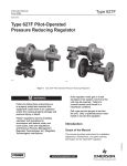
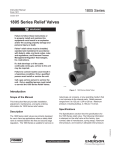
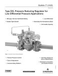
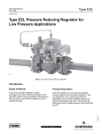
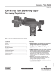
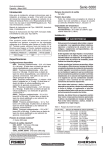
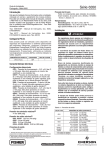
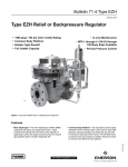
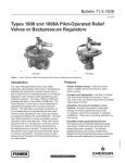
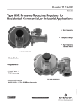
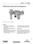
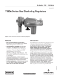
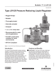
Bulletin 71.2:627F
February 2013
Type 627F Pilot-Operated Pressure
Reducing Regulator
W5607-1
W5641-1
Figure 1. Type 627F Pressure Reducing Regulators
The Type 627F pilot-operated (Type 6351F pilot)
pressure reducing regulator (Figure 1) provides
superior performance when used in pressure-factor
measurement(fixed-factorbilling)applications.The
Type 627F includes a factory-installed Type 6351F
pilotandhasexternalregistrationthatrequiresa
downstream control line.
Features
• Accurate for Pressure-Factor Measurement
Applications—Pilot action controls pressure to
within ±1 percent of the absolute outlet pressure
(psia) setting at full valve disk travel, resulting in
higher capacity than could be obtained without
a pilot. This capability results in low-pressure
variationsoverbroadflowrangesandinlet
pressure ranges.
pipeline. A two-bolt connection between the body
anddiaphragmcasingsimplifiesdisassembly
for maintenance.
• Installation Adaptability—The diaphragm case
and/or regulator body can be rotated in any of
four positions to allow regulator installation in
locations with limited space. The regulator may be
installed in any position without affecting operation
as long as the spring case vent is protected from
the elements.
• Tamper-Resistant—An adjusting screw locknut
and protective cap (Figure 2) is standard on all
Type 6351F pilots to discourage tampering with
the pressure setting.
• Wide Range of Flow Capabilities—A selection of
bodyandorificesizesisavailabletosatisfy
variousflowrequirements.
• Tight Shutoff Capability—Aflat-faceddiskof
Nitrile(NBR)providesexcellentshutoffcapability.
• Easy to Maintain—Trim parts can be replaced
without removing the regulator body from the
www.fisherregulators.com
D101544X012
Introduction
Bulletin 71.2:627F
Specifications
Body Sizes and End Connection Styles
Construction Materials (continued)
Ductile iron: 3/4, 1, or 2 NPT
Disk Assembly: Aluminum (standard) or
Steel: 3/4, 1, or 2 NPT;
Stainless steel holder with Nitrile (NBR) disk
NPS 1 or 2 / DN 25 or 50, CL150 RF,
O-Rings and Diaphragm: Nitrile (NBR)
CL300 RF, CL600 RF, PN 16/25/40 RF
Tension Spring: Plated steel
Type 6351F Pilot
Maximum Inlet and Differential Pressures(1)
Body: Stainless steel
See Table 2
Spring Case: Aluminum
Diaphragm: Nylon fabric coated with Nitrile (NBR)
Minimum Pressure Differential
Inner Valve Plug: Stainless steel/Nitrile (NBR) or 20 psid / 1.4 bar d
Stainless steel/Fluorocarbon (FKM)
Outlet Pressure Ranges(1)
Stem: Stainless steel
5 to 100 psig / 0.34 to 6.9 bar
Control Spring: Zinc-plated steel
See Table 1
Valve Spring: Stainless steel
Pusher Post: Aluminum or Stainless steel
Maximum Emergency Outlet Pressure(1)
Diaphragm Plate, Lower Spring Guide, and 250 psig / 17.2 bar for all Type 627F actuators Adjusting Screw: Zinc-plated steel
and Type 6351F pilot components.
Outlet Pressure Accuracy
±1% of absolute pressure setting(1) (psia or bar absolute) when inlet pressure is held within
allowable variations shown in Table 3; droop does not exceed 1% of absolute pressure setting for flow rates shown in Tables 6 through 8.
Temperature Capabilities(1)
-20 to 180°F / -29 to 82°C
Pressure Registration
External through 1/4 NPT (internal) control line connection (see Figure 2)
Flow Coefficients
See Table 4
Pilot Spring Case Vent Connection
1/4 NPT (internal) with removable screened vent assembly
IEC Sizing Coefficients
See Table 5
Pilot Connections
1/4 NPT (internal)
Typical Regulating Capacities
See Tables 6 through 8 and Capacity
Information section
Approximate Weights
NPT body with Ductile Iron or Steel Casings: 10 pounds / 4.5 kg
NPT body with Aluminum Casings:
6.3 pounds / 2.9 kg
Flanged body with Steel Casings:
18 pounds / 8.2 kg
Flanged body with Ductile Iron Casings:
14 pounds / 6.4 kg
Typical Performance Curve
See Figure 3
Construction Materials
Type 627F Main Regulator
Body: Ductile iron (standard) or steel
Spring Case and Diaphragm Case: Die cast Aluminum (standard), Ductile iron, or Steel
Orifice: Aluminum (standard) or Stainless steel
External Dimensions
See Figure 4
1. The pressure/temperature limits in this Bulletin and any applicable standard or code limitation should not be exceeded.
2
Bulletin 71.2:627F
FIELD INSTALLED
DOWNSTREAM
CONTROL LINE
SPRING SEAT BOLT,
THIS IS NOT AN
ADJUSTING SCREW
FILTER
(FACTORY
INSTALLATION
OPTIONAL)
RESTRICTION
(BLEED)
TENSION
SPRING
PILOT DIAPHRAGM
MAIN REGULATOR
DIAPHRAGM
VALVE
DISK
PILOT ADJUSTING
SCREW
TYPE 6351F PILOT
LEVER
TYPE 627F REGULATOR
PILOT SUPPLY TUBING
(FACTORY INSTALLATION OPTIONAL)
A6558
INLET PRESSURE
OUTLET PRESSURE
ATMOSPHERIC PRESSURE
LOADING PRESSURE
Figure 2. Type 627F Pilot-Operated Pressure Reducing Regulator Operational Schematic
3
Bulletin 71.2:627F
Table 1. Outlet Pressure Ranges
PILOT CONTROL SPRING INFORMATION
OUTLET PRESSURE RANGE
PILOT TYPE
6351F
psig
bar
5 to 35
35 to 100
0.34 to 2.4
2.4 to 6.9
Part Number
Color Code
1B788327022
1K748527022
Unpainted
Red
Wire Diameter
Free Length
Inches
mm
Inches
mm
0.142
0.192
3.61
4.88
2.13
2.19
54.1
55.6
Table 2. Maximum Allowable Inlet Pressures and Pressure Differential
ORIFICE SIZE
MAXIMUM INLET PRESSURE
MAXIMUM PRESSURE DIFFERENTIAL
Inches
mm
psig
bar
psi
bar
3/8 x 1/8
3/8 x 1/4
3/8
1/2
9.5 x 3.2
9.5 x 6.4
9.5
13
250
250
250
125
17.2
17.2
17.2
8.6
250
250
250
125
17.2
17.2
17.2
8.6
Table 3. Additional Specifications
ALLOWABLE INLET PRESSURE RANGE FOR MAINTAINING OUTLET PRESSURE WITHIN
±1% OF THE ABSOLUTE OUTLET PRESSURE SETTING(1)
ORIFICE SIZE
5 psig / 0.34 bar
30 psig / 2.1 bar
40 psig / 2.8 bar
60 psig / 4.1 bar
100 psig / 6.9 bar
Inches
mm
psig
bar
psig
bar
psig
bar
psig
bar
psig
bar
3/8 x 1/8
3/8 x 1/4
3/8
1/2
9.5 x 3.2
9.5 x 6.4
9.5
13
30 to 250
30 to 250
30 to 250
25 to 125
2.1 to 17.2
2.1 to 17.2
2.1 to 17.2
1.7 to 8.6
55 to 250
55 to 250
55 to 250
50 to 125
3.8 to 17.2
3.8 to 17.2
3.8 to 17.2
3.4 to 8.6
65 to 250
65 to 250
65 to 250
60 to 125
4.5 to 17.2
4.5 to 17.2
4.5 to 17.2
4.1 to 8.6
85 to 250
85 to 250
85 to 250
80 to 125
5.9 to 17.2
5.9 to 17.2
5.9 to 17.2
5.5 to 8.6
125 to 250
125 to 250
125 to 250
120 to 125
8.6 to 17.2
8.6 to 17.2
8.6 to 17.2
8.3 to 8.6
1. For best performance, outlet pressure setting should be made using an inlet pressure that is midway between the highest and lowest expected inlet pressure.
Table 4. Flow Coefficients
ORIFICE SIZE
3/4 NPT BODY
Wide-Open
Wide-Open
Inches
mm
Cg
Cv
3/8 x 1/8
9.5 x 3.2
12.5
0.43
3/8 x 1/4
9.5 x 6.4
50
1.63
3/8 9.5
108
1/2
13
190
NPS 1 / DN 25 BODY
Wide-Open
Wide-Open
Cg
Cv
29.1
12.5
0.43
30.6
50
1.71
2.99
36.1
108
4.87
39.0
190
C1
NPS 2 / DN 50 BODY
Wide-Open
Wide-Open
Cg
Cv
29.4
12.5
0.43
29.2
29.3
52
1.66
31.3
3.42
31.6
115
3.39
33.9
5.29
35.9
200
5.01
39.9
C1
C1
Table 5. IEC Sizing Coefficients
ORIFICE SIZE
4
XT
Inches
mm
3/4 NPT body
NPS 1 / DN 25 body
NPS 2 / DN 50 body
1/8 3.2
0.54
0.55
0.54
1/4
6.4
0.59
0.54
0.62
3/8
9.5
0.82
0.63
0.73
1/2
13
0.96
0.82
1.01
FD
FL
0.79
0.50
0.87
0.89
0.86
Bulletin 71.2:627F
Principle Operation
The superior performance of a Type 627F regulator is
due to the amplifying effect of the pilot and the two-path
control system (Figure 2). Changes in outlet pressure
act quickly on the main regulator diaphragm which
repositions the valve disk to provide fast response to
system changes. Simultaneously, the pilot amplifies
system pressure changes to position the main
regulator valve disk for precise pressure control.
Inlet pressure is used for the pilot supply pressure.
If downstream flow increases, lowering the outlet
pressure below the regulator setpoint, pressure on the
pilot diaphragm and the lever side of the main regulator
diaphragm decreases. The pilot opens to supply the
required loading pressure increase. The increased
loading pressure from the pilot overcomes the main
regulator spring force, and the main regulator valve
disk moves farther open to supply the required flow. When downstream pressure increases due to lowered
demand, greater pressure is registered on the pilot
diaphragm and the lever side of the main regulator
diaphragm. The pilot closes, and the excess loading
pressure bleeds off to downstream, through the pilot
restriction. With the lower loading pressure, the spring
can move the main regulator disk closer to the orifice.
Under no flow conditions, the excess loading pressure
bleeds through the pilot restriction to the downstream
system until the loading pressure and outlet pressure
equalize. The main valve is closed by the spring and
the bleed stops.
Installation
The Type 627F regulators may be installed in any
position, as long as flow will be in the same direction
as that indicated by the body arrow. These regulators
should be installed so that their spring case vents are
protected from anything that might clog them.
Emerson™ provides an instruction manual with
every regulator shipped. Refer to this for complete
installation, operation, and maintenance instructions.
Included is a complete listing of individual parts and
recommended spare parts.
Overpressure Protection
To avoid overpressure, provide appropriate pressure
relieving or pressure limiting devices to ensure that
none of the limits in the specifications section is
exceeded. Regulator operation within ratings does
not prevent the possibility of damage from external
sources such as debris in the pipeline. Inspect the
regulator for damage after any overpressure condition.
Refer to the relief sizing coefficients in the
specifications table and the Capacity Information
section to determine the required external relief
valve capacity.
Capacity Information
Natural gas regulating capacities at selected inlet
pressures and outlet pressure settings are given in
Tables 6 through 8. Flows are in SCFH (60°F and
14.7 psia) of 0.6 specific gravity natural gas. To
determine the equivalent capacities for other gases,
multiply the table capacity by the following appropriate
conversion factor: 0.775 for air, 0.789 for nitrogen,
0.625 for propane, or 0.548 for butane. For gases of
other specific gravities, multiply the given capacity by
0.775, and divide by the square root of the appropriate
specific gravity.
Then, if capacity is desired in normal cubic meters
per hour (Nm3/h) at 0°C and 1.01325 bar, multiply
SCFH by 0.0268.
To determine wide-open flow capacities for relief sizing
use the following formula:
Q =
520 CgP1SIN
GT
3417
C1
P
P1
DEG
where,
C1 =Cg/Cv (see Specifications table)
Cg = Gas sizing coefficient (see Specifications table)
G = Gas specific gravity (air = 1.0)
P1 = Valve inlet pressure, psia
P= Pressure drop across valve, psi
Q = Gas flow rate, SCFH
T = Absolute temperature of gas at inlet, °Rankine
To obtain the published capacities, the inlet and outlet
piping should be the same as the regulator size.
Overpressurizing any portion of a regulator or associated
equipment may cause personal injury, leakage, or
property damage due to bursting of pressure-containing
parts or explosion of accumulated gas.
5
Bulletin 71.2:627F
Table 6. F
low Capacities in SCFH / Nm3/h of 0.6 Specific Gravity Natural Gas at 1% Droop in Absolute Outlet Pressure for 3/4 NPT
(Downstream Control Line in Body Size Piping)
PILOT SPRING RANGE,
PART NUMBER, AND
COLOR CODE
OUTLET
PRESSURE
SETTING
psig
5
10
30
40
35 to 100 psig /
2.4 to 6.9 bar
1K748527202
Red
50
60
75
Orifice Diameter, Inches / mm
bar
psig
bar
0.34
30
40
50
60
80
100
125
150
200
250
2.1
2.8
3.5
4.1
5.5
6.9
8.6
10.3
13.8
17.2
700
860
1020
1170
1490
1800
2200
2580
3370
4170
18.8
23.1
27.3
31.4
39.9
48.2
59.0
69.1
90.3
112
2840
3500
4140
4780
6060
7340
8940
10,500
13,700
15,500
76.1
93.8
111
128
162
197
240
281
367
415
5780
7480
8850
10,200
12,900
15,000
15,500
15,500
15,500
15,500
155
200
237
273
346
415
415
415
415
415
9730
13,100
15,400
15,500
15,500
15,500
15,500
261
351
413
415
415
415
415
0.69
30
40
50
60
80
100
125
150
200
250
2.1
2.8
3.5
4.1
5.5
6.9
8.6
10.3
13.8
17.2
690
860
1020
1170
1490
1800
2200
2580 3370
4170
18.5
23.1
27.3
31.4
39.9
48.2
59.0
69.1
90.3
112
2760
3500
4140
4780
6060
7340
8940
10,500
13,700
16,900
74.0
93.8
111
128
192
197
240
281
367
453
5480
7480
8850
10,200
12,900
15,700
17,500
19,500
19,500
19,500
147
200
237
273
346
421
469
523
523
523
8500
13,100
15,400
17,800
19,500
19,500
19,500
228
351
413
477
523
523
523
1.4
30
40
50
60
80
100
125
150
200
250
2.1
2.8
3.5
4.1
5.5
6.9
8.6
10.3
13.8
17.2
590
820
1000
1170
1490
1800
2200
2580
3370
4170
15.8
22.0
26.8
31.4
39.9
48.2
59.0
69.1
90.3
112
2310
3250
4030
4780
6060
7340
8940
10,500
13,700
16,900
61.9
87.1
108
128
162
197
240
281
367
453
4360
6320
8010
10,200
12,900
15,700
19,100
22,500
28,000
28,000
117
169
215
273
346
421
512
603
750
750
6000
10,000
13,400
17,800
22,600
24,000
28,000
161
268
359
477
606
634
750
2.1
50
60
80
100
125
150
200
250
3.5
4.1
5.5
6.9
8.6
10.3
13.8
17.2
930
1140
1490
1800
2200
2580
3370
4170
24.9
30.6
39.9
48.2
59.0
69.1
90.3
112
3680
4530
6060
7340
8940
10,500
13,700
16,900
98.6
121
162
197
240
281
367
453
7090
8880
12,900
15,700
19,100
22,500
28,000
28,000
190
238
346
421
512
603
750
750
11,000
14,800
22,600
27,400
33,300
295
397
606
734
892
2.8
60
80
100
125
150
200
250
4.1
5.5
6.9
8.6
10.3
13.8
17.2
1030
1450
1790
2200
2580
3370
4170
27.6
38.9
48.0
59.0
69.1
90.3
112
4070
5790
7340
8940
10,400
13,500
16,900
109
155
197
240
279
362
453
7770
11,400
15,700
19,100
20,000
20,000
20,000
208
306
421
512
536
536
536
10,400
19,000
27,400
33,300
279
509
734
892
3.5
60
70
80
100
125
150
200
250
4.1
4.8
5.5
6.9
8.6
10.3
13.8
17.2
820
1130
1370
1770
2200
2590
3370
4170
22.0
30.3
36.7
47.4
59.0
69.4
90.3
112
3210
4450
5420
7060
8940
10,400
13,500
16,900
86.0
119
145
189
240
279
362
453
5970
8430
10,500
14,000
19,100
22,500
29,000
29,000
160
226
281
375
512
603
777
777
7500
10,600
17,000
23,300
33,300
201
284
456
624
892
4.1
80
100
125
150
200
250
5.5
6.9
8.6
10.3
13.8
17.2
1220
1700
2170
2580
3370
4170
32.7
45.6
58.2
69.1
90.3
112
4790
6730
8700
10,300
13,500
16,900
128
180
233
276
362
453
9050
13,100
17,300
22,500
29,400
32,000
243
351
464
603
788
858
12,000
21,600
28,400
322
579
761
5.2
100
125
150
200
250
6.9
8.6
10.3
13.8
17.2
1490
2080
2550
3370
4170
39.9
55.7
68.3
90.3
112
5870
8250
10,200
13,500
16,900
157
221
273
362
453
11,100
16,000
20,300
29,400
36,200
297
429
544
788
970
17,000
26,600
456
713
5 to 35 psig /
0.34 to 2.4 bar
1B788327022
Silver
20
3/4 NPT BODY SIZE
INLET
PRESSURE
3/8 x 1/8 / 9.5 x 3.2
– Maximum operating inlet pressure is exceeded.
- continued 6
3/8 x 1/4 / 9.5 x 6.4
3/8 / 9.5
1/2 / 13
Bulletin 71.2:627F
Table 6. F
low Capacities in SCFH / Nm3/h of 0.6 Specific Gravity Natural Gas at 1% Droop in Absolute Outlet Pressure for 3/4 NPT
(Downstream Control Line in Body Size Piping) (continued)
PILOT SPRING RANGE,
PART NUMBER, AND
COLOR CODE
35 to 100 psig /
2.4 to 6.9 bar
1K748527202
Red
OUTLET
PRESSURE
SETTING
psig
100
3/4 NPT BODY SIZE
INLET
PRESSURE
bar
psig
bar
6.9
125
150
200
250
8.6
10.3
13.8
17.2
Orifice Diameter, Inches / mm
3/8 x 1/8 / 9.5 x 3.2
1660
2360
3330
4170
44.5
63.3
89.2
112
3/8 x 1/4 / 9.5 x 6.4
6680
9320
13,400
16,900
179
250
359
453
3/8 / 9.5
12,500
17,900
26,600
36,200
1/2 / 13
335
480
713
970
18,000
482
– Maximum operating inlet pressure is exceeded.
Table 7. F
low Capacities in SCFH / Nm3/h of 0.6 Specific Gravity Natural Gas at 1% Droop in Absolute Outlet Pressure for NPS 1 / DN 25
(Downstream Control Line in Body Size Piping)
PILOT SPRING RANGE,
PART NUMBER, AND
COLOR CODE
OUTLET
PRESSURE
SETTING
psig
5
10
30
35 to 100 psig /
2.4 to 6.9 bar
1K748527202
Red
40
Orifice Diameter, Inches / mm
bar
psig
bar
0.34
30
40
50
60
80
100
125
150
200
250
2.1
2.8
3.5
4.1
5.5
6.9
8.6
10.3
13.8
17.2
700
860
1020
1170
1490
1800
2200
2580
3370
4170
18.8
23.1
27.3
31.4
39.9
48.2
59.0
69.1
90.3
112
2840
3500
4140
4780
6060
7340
8940
10,500
13,700
16,900
76.1
93.8
111
128
162
197
240
281
367
453
6040
7480
8850
10,200
12,900
15,700
18,500
18,500
18,500
18,500
162
200
237
273
346
421
496
496
496
496
10,100
13,100
15,400
17,800
18,500
18,500
18,500
271
351
413
477
496
496
496
6.9
30
40
50
60
80
100
125
150
200
250
2.1
2.8
3.5
4.1
5.5
6.9
8.6
10.3
13.8
17.2
690
860
1020
1170
1490
1800
2200
2580
3370
4170
18.5
23.1
27.3
31.4
39.9
48.2
59.0
69.1
90.3
112
2760
3500
4140
4780
6060
7340
8940
10,500
13,700
16,900
74.0
93.8
111
128
162
197
240
281
367
453
5840
7480
8850
10,200
12,900
15,700
19,100
22,500
22,600
22,600
157
200
237
273
346
421
512
603
606
606
8930
13,100
15,400
17,800
22,600
22,600
22,600
239
351
413
477
606
606
606
1.4
30
40
50
60
80
100
125
150
200
250
2.1
2.8
3.5
4.1
5.5
6.9
8.6
10.3
13.8
17.2
590
820
1000
1170
1490
1800
2200
2580
3370
4170
15.8
22.0
26.8
31.4
39.9
48.2
59.0
69.1
90.3
112
2310
3250
4030
4780
6060
7340
8940
10,500
13,700
16,900
61.9
87.1
108
128
162
197
240
281
367
453
4820
6830
8500
10,200
12,900
15,700
19,100
22,500
29,400
33,300
129
183
228
273
346
421
512
603
788
892
6400
10,500
13,400
17,800
22,600
27,400
33,300
172
281
359
477
606
734
892
2.1
50
60
80
100
125
150
200
250
3.5
4.1
5.5
6.9
8.6
10.3
13.8
17.2
930
1140
1490
1800
2200
2580
3370
4170
24.9
30.6
39.9
48.2
59.0
69.1
90.3
112
3680
4530
6060
7340
8940
10,500
13,700
16,900
98.6
121
162
197
240
281
367
453
7720
9540
12,900
15,700
19,100
22,500
29,400
36,200
207
256
346
421
512
603
788
970
11,700
15,600
22,600
27,400
33,300
314
418
606
734
892
2.8
60
80
100
125
150
200
250
4.1
5.5
6.9
8.6
10.3
13.8
17.2
1030
1450
1790
2200
2580
3370
4170
27.6
38.9
48.0
59.0
69.1
90.3
112
4070
5790
7340
8940
10,400
13,500
16,900
109
155
197
240
279
362
453
8530
12,200
15,700
19,100
22,500
29,400
36,200
229
327
421
512
603
788
970
11,000
20,000
27,400
33,300
300
536
734
892
5 to 35 psig /
0.34 to 2.4 bar
1B788327022
Silver
20
NPS 1 / DN 25 BODY SIZE
INLET
PRESSURE
3/8 x 1/8 / 9.5 x 3.2
3/8 x 1/4 / 9.5 x 6.4
3/8 / 9.5
1/2 / 13
– Maximum operating inlet pressure is exceeded.
- continued -
7
Bulletin 71.2:627F
Table 7. F
low Capacities in SCFH / Nm3/h of 0.6 Specific Gravity Natural Gas at 1% Droop in Absolute Outlet Pressure for NPS 1 / DN 25
(Downstream Control Line in Body Size Piping) (continued)
PILOT SPRING RANGE,
PART NUMBER, AND
COLOR CODE
OUTLET
PRESSURE
SETTING
psig
Orifice Diameter, Inches / mm
bar
psig
bar
3.4
70
80
100
125
150
200
250
4.8
5.5
6.9
8.6
10.3
13.8
17.2
1130
1370
1770
2200
2590
3370
4170
30.3
36.7
47.4
59.0
69.4
90.3
112
4450
5420
7060
8940
10,400
13,500
16,900
119
145
189
240
279
362
453
9300
11,400
14,900
19,100
22,500
29,400
36,200
249
306
399
512
603
788
970
11,200
18,300
24,400
33,300
300
490
654
892
4.1
80
100
125
150
200
250
5.5
6.9
8.6
10.3
13.8
17.2
1220
1700
2170
2580
3370
4170
82.7
45.6
58.2
69.1
90.3
112
4790
6730
8700
10,300
13,500
16,900
128
180
233
276
362
453
10,000
14,200
18,400
22,500
29,400
36,200
268
381
493
603
788
970
12,900
22,900
30,300
346
614
812
75
5.2
100
125
150
200
250
6.9
8.6
10.3
13.8
17.2
1490
2080
2550
3370
4170
39.9
55.7
68.3
90.3
112
5870
8250
10,200
13,500
16,900
157
221
273
362
453
12,300
16,900
20,300
29,400
36,200
330
453
544
788
970
18,000
28,100
482
753
8.6
10.3
13.8
17.2
1660
2360
3330
4170
44.5
63.3
89.2
112
6680
9320
13,400
16,900
179
250
359
453
13,900
20,000
28,300
36,200
373
536
758
970
520
6.9
125
150
200
250
19,400
100
50
35 to 100 psig /
2.4 to 6.9 bar
1K748527202
Red
NPS 1 / DN 25 BODY SIZE
INLET
PRESSURE
60
3/8 x 1/8 / 9.5 x 3.2
3/8 x 1/4 / 9.5 x 6.4
3/8 / 9.5
1/2 / 13
– Maximum operating inlet pressure is exceeded.
Table 8. F
low Capacities in SCFH / Nm3/h of 0.6 Specific Gravity Natural Gas at 1% Droop in Absolute Outlet Pressure for NPS 2 / DN 50
(Downstream Control Line in Body Size Piping)
PILOT SPRING RANGE,
PART NUMBER, AND
COLOR CODE
OUTLET
PRESSURE
SETTING
psig
5
5 to 35 psig /
0.34 to 2.4 bar
1B788327022
Silver
10
20
NPS 2 / DN 50 BODY SIZE
INLET
PRESSURE
Orifice Diameter, Inches / mm
bar
psig
bar
3/8 x 1/8 / 9.5 x 3.2
0.34
30
40
50
60
80
100
125
150
200
250
2.1
2.8
3.5
4.1
5.5
6.9
8.6
10.3
13.8
17.2
700
860
1020
1170
1490
1800
2200
2580
3370
4170
18.8
23.1
27.3
31.4
39.9
48.2
59.0
69.1
90.3
112
2840
3500
4140
4780
6060
7340
8940
10,500
13,700
16,900
76.1
93.8
111
128
162
197
240
281
367
453
6150
7760
9180
10,600
13,400
16,300
19,800
23,400
30,000
30,000
165
208
246
284
359
437
531
627
804
804
10,100
13,800
16,300
18,800
23,800
28,900
30,000
271
370
437
504
638
775
804
0.69
30
40
50
60
80
100
125
150
200
250
2.1
2.8
3.5
4.1
5.5
6.9
8.6
10.3
13.8
17.2
690
860
1020
1170
1490
1800
2200
2580
3370
4170
18.5
23.1
27.3
31.4
39.9
48.2
59.0
69.1
90.3
112
2760
3500
4140
4780
6060
7340
8940
10,500
13,700
16,900
74.0
93.8
111
128
162
197
240
281
367
453
5870
7760
9130
10,600
13,400
16,300
19,800
23,400
30,500
37,600
157
208
246
284
359
437
531
627
817
1008
9500
13,800
16,300
18,800
23,800
28,900
35,100
255
370
437
504
638
775
941
1.4
30
40
50
60
80
100
125
150
200
250
2.1
2.8
3.5
4.1
5.5
6.9
8.6
10.3
13.8
17.2
590
820
1000
1170
1490
1800
2200
2580
3370
4170
15.8
22.0
26.8
31.4
39.9
48.2
59.0
69.1
90.3
112
2310
3250
4030
4780
6060
7340
8940
10,500
13,700
16,900
61.9
97.1
108
128
162
197
240
281
367
453
4750
6820
8570
10,600
13,400
16,300
19,800
23,400
30,500
37,600
127
183
230
284
359
437
531
627
817
1008
7000
10,900
13,900
18,800
23,800
28,900
35,100
188
292
373
410
638
775
941
– Maximum operating inlet pressure is exceeded.
- continued 8
3/8 x 1/4 / 9.5 x 6.4
3/8 / 9.5
1/2 / 13
Bulletin 71.2:627F
Table 8. F
low Capacities in SCFH / Nm3/h of 0.6 Specific Gravity Natural Gas at 1% Droop in Absolute Outlet Pressure for NPS 2 / DN 50
(Downstream Control Line in Body Size Piping) (continued)
PILOT SPRING RANGE,
PART NUMBER, AND
COLOR CODE
5 to 35 psig /
0.34 to 2.4 bar
1B788327022
Silver
OUTLET
PRESSURE
SETTING
psig
Orifice Diameter, Inches / mm
bar
psig
bar
2.1
50
60
80
100
125
150
200
250
3.5
4.1
5.5
6.9
8.6
10.3
13.8
17.2
930
1140
1490
1800
2200
2580
3370
4170
24.9
30.6
39.9
48.2
59.0
69.1
90.3
112
3680
4530
6060
7340
8940
10,500
13,700
16,900
98.6
121
162
197
240
281
367
453
7670
9540
13,500
16,300
19,800
23,400
30,500
37,600
206
256
362
437
531
627
817
1008
12,100
15,300
23,800
28,900
35,100
324
410
638
775
941
2.8
60
80
100
125
150
200
250
4.1
5.5
6.9
8.6
10.3
13.8
17.2
1030
1450
1790
2200
2580
3370
4170
27.6
38.9
48.0
59.0
69.1
90.3
12
4070
5790
7340
8940
10,400
13,500
16,900
109
155
197
240
279
362
453
8440
12,300
16,300
19,800
23,400
30,500
37,600
226
330
437
531
627
817
1008
12,000
19,700
28,900
35,100
322
528
775
941
3.4
70
80
100
125
150
200
250
4.8
5.5
6.9
8.6
10.3
13.8
17.2
1130
1370
1770
2200
2590
3370
4170
30.3
36.7
47.4
59.0
69.4
90.3
112
4450
5420
7060
8940
10,400
13,500
16,900
119
145
189
240
279
362
453
8460
11,300
15,000
19,800
23,400
30,500
37,600
227
303
402
531
627
817
1008
14,000
17,900
24,200
35,100
375
480
649
941
4.1
80
100
125
150
200
250
5.5
6.9
8.6
10.3
13.8
17.2
1220
1700
2170
2580
3370
4170
32.7
45.6
58.2
69.1
90.3
112
4790
6730
8700
10,300
13,500
16,900
128
180
233
276
362
453
9860
14,100
18,500
23,400
30,500
37,600
264
378
496
627
817
1008
14,000
22,400
30,000
375
600
804
75
5.2
100
125
150
200
250
6.9
8.6
10.3
13.8
17.2
1490
2080
2550
3370
4170
39.9
55.7
68.3
90.3
112
5870
8250
10,200
13,500
16,900
157
221
273
362
453
12,100
17,300
21,700
30,500
37,600
324
464
582
817
1008
18,800
27,600
504
740
8.6
10.3
13.8
17.2
1660
2360
3330
4170
44.5
63.3
89.2
112
6680
9320
13,400
16,900
179
250
359
453
13,700
19,400
28,500
37,600
367
520
764
1008
568
6.9
125
150
200
250
21,200
100
30
40
50
35 to 100 psig /
2.4 to 6.9 bar
1K748527202
Red
NPS 2 / DN 50 BODY SIZE
INLET
PRESSURE
60
3/8 x 1/8 / 9.5 x 3.2
3/8 x 1/4 / 9.5 x 6.4
3/8 / 9.5
1/2 / 13
– Maximum operating inlet pressure is exceeded.
51
3.5
50
± 1%
2
3.4
OUTLET PRESSURE, bar
OUTLET PRESSURE, psig
52
49
0
0/0
5 / 0.1
10 / 0.3
15 / 0.4
20 / 0.5
25 / 0.7
30 / 0.8
0.00
35 / 0.9
FLOW RATE THOUSANDS OF SCFH / Nm3/h OF 0.6 SPECIFIC GRAVITY NATURAL GAS
2 3/8-INCH / 9.5 mm ORIFICE. ACTUATOR SPRING 35 to 100 psig /
2.4 to 6.9 bar RANGE (RED COLOR CODE) PILOT SPRING 200 psig / 13.8 bar
INLET PRESSURE
Figure 3. Typical Performance Curve for 3/4 NPT Type 627F Regulator
9
Bulletin 71.2:627F
10.5 / 267
5.50 / 140
8.06 / 205
1.00 /
25.4
A
TYPE P594-1
FILTER
(OPTIONAL)
TYPE 6351F
B
Ø 4.69 /
119
G
D
12B2138_E
F
9.12 / 232
5.50 / 140
TYPE 6351F
8.06 / 205
1/4 NPT SUPPLY
CONNECTION
WITH OPTIONAL
TYPE P594-1 FILTER
B
A
Ø 4.69 /
119
G
D
12B7144_C
INCHES / mm
Figure 4. Dimensions
Table 9. Dimensions
BODY SIZE
Inches
A
B
D
F
G
3/4
----
NPT
4.06
103
1.94
49
6.75
171
----
----
2.00
51
1
----
NPT
4.06
103
1.94
49
6.75
171
----
----
2.00
51
CL150 RF
7.25
184
3.62
92
2.12
54
CL300 RF
7.75
197
3.88
99
2.44
62
CL600 RF
8.25
210
4.12
105
2.44
62
PN 16/25/40
7.80
198
3.90
99
2.31
59
NPT
5.00
127
2.50
64
2.62
67
CL150 RF
10.00
254
5.00
127
3.00
76
CL300 RF
10.50
267
5.25
133
3.25
83
CL600 RF
11.25
286
5.62
143
3.25
83
PN 16/25/40
10.31
262
5.16
131
3.25
83
1
2
10
DN
DIMENSIONS, Inches / mm
END CONNECTION
STYLE
25
50
6.75
171
4.38
111
7.12
181
----
----
7.12
181
4.75
121
Bulletin 71.2:627F
Ordering Information
Application
Construction
When ordering, specify:
Refer to the specifications and to each referenced
table; specify the desired selection whenever there is a
choice to be made. The standard assembly position is
shown in Figure 1, but an alternate assembly position
may be factory-ordered or can be accomplished in the
field by unbolting the body or spring case using the
instructions in the appropriate section of the instruction
manual. For installation dimensions, refer to Figure 4.
1. Type of regulator
2. Body size
3. Body material and trim material
4. Orifice size in inches / mm
5. Control spring range in psig / bar
Ordering Guide
Body Material, Body Size, and End Connection Style
(Select One)
Ductile Iron
3/4 NPT***
1 NPT***
2 NPT***
WCC Steel
3/4 NPT***
1 NPT***
NPS 1 / DN 25, CL150 RF**
NPS 1 / DN 25, CL300 RF**
NPS 1 / DN 25, CL600 RF**
NPS 1 / DN 25, PN 16/25/40**
2 NPT***
NPS 2 / DN 50, CL150 RF**
NPS 2 / DN 50, CL300 RF**
NPS 2 / DN 50, CL600 RF**
NPS 2 / DN 50, PN 16/25/40**
Spring Case and Diaphragm Casing Material
(Select One)
Trim Material (Select One)
Aluminum***
Stainless steel***
Orifice Size (Select One)
3/8 x 1/8-inch / 9.5 x 3.2 mm**
3/8 x 1/4-inch / 9.5 x 6.4 mm**
3/8-inch / 9.5 mm***
1/2-inch / 13 mm***
Outlet Pressure Range (Select One)
5 to 35 psig / 0.34 to 2.4 bar, Unpainted***
35 to 100 psig / 2.4 to 6.9 bar, Red***
Pilot Supply Filter (Optional)
Type P594-1
Pilot Supply Steel Tubing (Optional)
With Type P594-1 Filter
Without Filter
Replacement Parts Kit (Optional)
Yes, send one replacement parts kit to match this order.
Aluminum***
Ductile iron***
WCC steel***
11
Bulletin 71.2:627F
Specification Worksheet
Application:
Specific Use
Line Size
Gas Type and Specific Gravity
Gas Temperature
Does the Application Require Overpressure Protection? Yes No If yes, which is preferred:
Relief Valve Monitor Regulator Shutoff Device
Is overpressure protection equipment selection assistance
desired?
Pressure:
Maximum Inlet Pressure (P1max)
Minimum Inlet Pressure (P1min)
Downstream Pressure Setting(s) (P2)
Maximum Flow (Qmax)
Regulators Quick Order Guide
***
**
*
Readily Available for Shipment
Allow Additional Time for Shipment
Special Order, Constructed from Non-Stocked Parts. Consult
Your local Sales Office for Availability.
Availability of the product being ordered is determined by the component with the
longest shipping time for the requested construction.
Performance Required:
Accuracy Requirements?
Need for Extremely Fast Response?
Other Requirements:
Industrial Regulators
Natural Gas Technologies
TESCOM
Emerson Process Management
Regulator Technologies, Inc.
Emerson Process Management
Regulator Technologies, Inc.
Emerson Process Management
Tescom Corporation
USA - Headquarters
McKinney, Texas 75069-1872, USA
Tel: +1 800 558 5853
Outside U.S. +1 972 548 3574
USA - Headquarters
McKinney, Texas 75069-1872, USA
Tel: +1 800 558 5853
Outside U.S. +1 972 548 3574
USA - Headquarters
Elk River, Minnesota 55330-2445, USA
Tels: +1 763 241 3238
+1 800 447 1250
Asia-Pacific
Shanghai 201206, China
Tel: +86 21 2892 9000
Asia-Pacific
Singapore 128461, Singapore
Tel: +65 6770 8337
Europe
Selmsdorf 23923, Germany
Tel: +49 38823 31 287
Europe
Bologna 40013, Italy
Tel: +39 051 419 0611
Europe
Bologna 40013, Italy
Tel: +39 051 419 0611
Chartres 28008, France
Tel: +33 2 37 33 47 00
Asia-Pacific
Shanghai 201206, China
Tel: +86 21 2892 9499
Middle East and Africa
Dubai, United Arab Emirates
Tel: +971 4811 8100
For further information visit www.fisherregulators.com
The Emerson logo is a trademark and service mark of Emerson Electric Co. All other marks are the property of their prospective owners. Fisher is a mark owned by Fisher Controls International LLC,
a business of Emerson Process Management.
The contents of this publication are presented for informational purposes only, and while every effort has been made to ensure their accuracy, they are not to be construed as warranties or
guarantees, express or implied, regarding the products or services described herein or their use or applicability. We reserve the right to modify or improve the designs or specifications of such
products at any time without notice.
Emerson Process Management Regulator Technologies Inc. does not assume responsibility for the selection, use or maintenance of any product. Responsibility for proper selection, use and
maintenance of any Emerson Process Management Regulator Technologies Inc. product remains solely with the purchaser.
©Emerson Process Management Regulator Technologies, Inc., 1990, 2013; All Rights Reserved