1
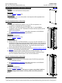
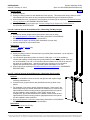
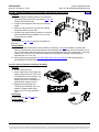
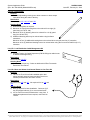
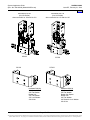
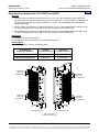
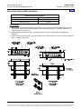
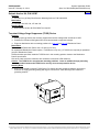
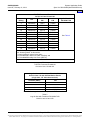
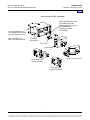
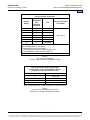
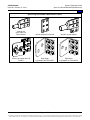
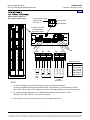
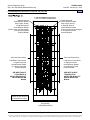
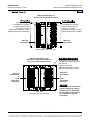
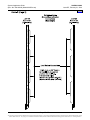
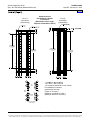
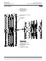
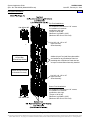
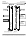
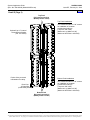
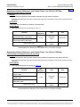
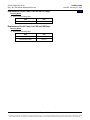
SAG582120600
Issue BF, February 21, 2014
System Application Guide
Spec. No. 582120600 (Model 801DB NVGB)
Home
Ordering Notes
1) Order as required.
2) Specify mounting location for each Distribution Panel per bay. This instructs the factory where to mount
each Distribution Panel when the bay is populated with different types of Distribution Panels.
3) Order distribution fuses, fuseholders, circuit breakers, and load lugs as required per Distribution Devices
and Lug Selection in ACCESSORY DESCRIPTIONS.
4) Order TVSS Device(s) as required per Transient Voltage Surge Suppressor (TVSS) Device in
ACCESSORY DESCRIPTIONS.
List 126: Optional Internal Ground/Return Bar, 6-Panel Bay (Full Bay Length)
Features
♦
Provides two full bay length internal ground/return bars (one per side).
♦
See Load Distribution Connections under Wiring Illustrations in ACCESSORY
DESCRIPTIONS for load termination specifications.
♦
Includes two (2) Input Lug Landing Plate Assemblies (one per side).
♦ Can be configured for top or bottom feed.
Restrictions
For use in List 106 or List 107 only.
Ordering Notes
1) Order as required.
2) Specify mounting location of included Input Lug Landing Plate Assemblies: top for top-feed
or bottom for bottom feed.
3) List 126 internal ground/return bars are rated for 1200 Amps. List 148 is available to
increase that capacity to 2400 Amps and provide additional cable landing points. Each bay
can accommodate (1) list 148. List 148 offers cable termination at the rear of the bay and
the option of a bonding strap. Mounting location (top or bottom) of List 148 will be
opposite that specified for the Input Lug Landing Plate Assemblies of List 126.
4) Order load lugs as required per Distribution Devices and Lug Selection in ACCESSORY
DESCRIPTIONS.
List 127: Optional Internal Ground/Return Bar, 6-Panel Bay (Panel Length)
Features
♦
Replaces a Distribution Panel on the left and right side with a panel length
internal ground/return bar.
♦
Consists of two (2) ground/return bar assemblies and two (2) blank cover
panels.
♦
For installation in top feed or bottom feed arrangements. When used in top
feed arrangements, ground bar assemblies are installed in top most left and
right Distribution Panel mounting positions (appropriate blank cover panels
are also installed in these positions). When used in bottom feed
arrangements, ground bar assemblies are installed in bottom most left and
right Distribution Panel mounting positions (appropriate blank cover panels
are also installed in these positions).
See Load Distribution Connections under Wiring Illustrations in ACCESSORY
DESCRIPTIONS for load termination specifications.
Restrictions
For use in List 106 or List 107 only.
♦
Page 16 of 72
This document is property of Emerson Network Power, Energy Systems, North America, Inc. and contains confidential and proprietary information owned by Emerson Network Power, Energy
Systems, North America, Inc. Any copying, use, or disclosure of it without the written permission of Emerson Network Power, Energy Systems, North America, Inc. is strictly prohibited.