1
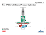
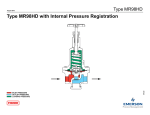
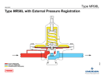
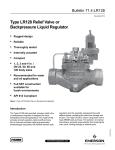
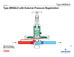
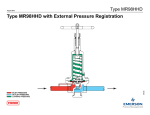
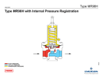
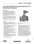
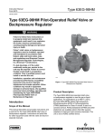
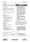
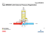
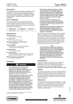
Installation Guide
English – April 2014
MR98 Series
This Installation Guide provides instructions for installation, startup
and adjustment. To receive a copy of the instruction manual,
contact your local Sales Office or view a copy at
www.fisherregulators.com. For further information refer to
MR98 Series Backpressure Regulators, Relief and Differential
Relief valves Instruction Manual, D103588X012.
P.E.D. Category
This product may be used as a safety accessory with pressure
equipment in the following Pressure Equipment Directive 97/23/EC
categories. It may also be used outside of the Pressure Equipment
Directive using Sound Engineering Practice (SEP) per table below.
TYPE
PRODUCT SIZE
BODY MATERIAL
CATEGORY
All
1/4 NPT, DN 15 to 25 /
1/2 to 1-inch
All available
materials
SEP
MR98H/
MR98HD
DN 40 and 50 /
1-1/2 and 2-inch
Steel and
Stainless Steel
II
Specifications
Available Constructions
Type MR98L: Direct-operated low pressure backpressure
regulator/relief valve with 0.14 to 2.6 bar / 2 to 38 psig set
pressure range
Type MR98H: Direct-operated high pressure backpressure
regulator/relief valve with 0.34 to 13.8 bar / 5 to 200 psig set
pressure range
Type MR98HH: Direct-operated high pressure backpressure/
relief valve with 10.3 to 25.9 bar / 150 to 375 psig set
pressure range
Type MR98LD: Pressure-loaded low pressure differential
pressure relief valve with 0.14 to 2.6 bar / 2 to 38 psi set
pressure range
Type MR98HD: Pressure-loaded high pressure differential
pressure relief valve with 0.34 to 13.8 bar / 5 to 200 psi set
pressure range
Type MR98HHD: Pressure-operated high pressure
backpressure/relief valve with 10.3 to 25.9 bar /
150 to 375 psi differential set pressure range
Body and Orifice Sizes
1/4 NPT body: 7.22 mm / 0.284-inch orifice
DN 15 / 1/2-inch body: 10.56 mm / 0.416-inch orifice
DN 20 and 25 / 3/4 and 1-inch bodies:
16.02 mm / 0.631-inch orifice
DN 40 and 50 / 1-1/2 and 2-inch bodies:
29 mm / 1.142-inch orifice
End Connection Styles
NPT, SWE and Welded and Integral CL150 RF, CL300 RF
and PN 16/25/40 RF; all sizes are fabricated with slip-on
flanges (for welded end connections) and are EN flanged
356-mm face-to-face (14-inch face-to-face)
Maximum Inlet and Outlet Pressure Rating
See Table 2
Maximum Cold Working Pressures of Body Size and Materials(1)(2)
See Table 2
Set Pressure Ranges(1)
See Table 1
Maximum Spring Case Loading Pressure for
Types MR98LD, MR98HD and MR98HHD (Spring Setting
Plus Loading Pressure)(1)(2)
Type MR98LD Spring Case
Gray Cast Iron: 3.4 bar / 50 psig
Steel or Stainless Steel: 8.6 bar / 125 psig
Type MR98HD Spring Case
Gray Cast Iron: 17.2 bar / 250 psig
Steel or Stainless Steel: 20.7 bar / 300 psig
Type MR98HHD Spring Case
Steel or Stainless Steel: 20.7 bar / 300 psig
Temperature Capabilities(1)
Elastomer Parts:
Nitrile (NBR) and Neoprene (CR): -40 to 82°C / -40 to 180°F
Fluorocarbon (FKM)(3): -18 to 149°C / 0 to 300°F
Ethylenepropylene (EPDM): -7 to 135°C / 20 to 275°F
Perfluoroelastomer (FFKM): -18 to 218°C / 0 to 425°F
Polytetrafluoroethylene (PTFE) Diaphragm protector:
-40 to 204°C / -40 to 400°F
Body Materials:
Gray Cast Iron: -29 to 208°C / -20 to 406°F
WCC Steel: -29 to 232°C / -20 to 450°F
LCC Steel: -40 to 232°C / -40 to 450°F
Stainless Steel, Monel® and Hastelloy® C:
-40 to 232°C / -40 to 450°F
Pressure Registration
Internal or External
Shutoff Classification Per ANSI/FCI 70-3-2004
Metal Seats: Class IV
PTFE: Class IV
Elastomer Seats: Class VI or better
Installation
!
Warning
Only qualified personnel shall install or service a
relief valve or backpressure regulator. Relief valve
or backpressure regulator should be installed,
operated and maintained in accordance with
international and applicable codes and regulations
and Emerson Process Management Regulator
Technologies, Inc. instructions.
If using a relief valve or backpressure regulator
on a hazardous or flammable fluid service,
personal injury and property damage could
occur due to fire or explosion of vented fluid
that may have accumulated. To prevent such
injury or damage, provide piping or tubing to
vent the fluid to a safe, well-ventilated area
or containment vessel. Also, when venting a
hazardous fluid, the piping or tubing should be
located far enough away from any buildings or
windows so to not create a further hazard and
the vent opening should be protected against
anything that could clog it.
Personal injury, equipment damage or leakage
due to escaping fluid or bursting of pressurecontaining parts may result if this relief valve or
backpressure regulator is overpressured or is
installed where service conditions could exceed
Monel® is a mark owned by Special Metals Corporation.
Hastelloy® C is a mark owned by Haynes International, Inc.
1. The pressure/temperature limits in this Installation Guide and any applicable standard or code limitation should not be exceeded.
2. The pressure limits given are based on the body size and body materials only. Actual pressure limits of the assembled regulator may decrease and vary depending on the
temperature, body end connection, diaphragm, seat and/or trim material of the regulator.
3. Fluorocarbon (FKM) is limited to 93°C / 200°F hot water.
www.fisherregulators.com
D103588X014
Introduction
MR98 Series
Table 1. MR98 Series Body Sizes and Pressure Ranges
BODY SIZE
TYPE
CONTROL PRESSURE RANGE(1)
DN
MR98L and MR98LD
Inch
15, 20 and 25
15, 20 and 25
1/4 NPT, 1/2, 3/4 and 1
40 and 50
15, 20 and 25
psig
0.14 to 0.48
2 to 7
0.41 to 0.97
6 to 14
0.83 to 1.7
12 to 25
1.4 to 2.6
20 to 38
1.0 to 2.4
15 to 35
1.7 to 5.2
25 to 75
4.8 to 9.7
70 to 140
9.0 to 13.8
130 to 200
1/4 NPT, 1/2, 3/4 and 1
MR98H and MR98HD
MR98HH and MR98HHD
bar
0.34 to 2.4
5 to 35
1.4 to 4.5
20 to 65
3.4 to 6.9
50 to 100
1-1/2 and 2
1/4 NPT, 1/2, 3/4 and 1
5.2 to 11.7
75 to 170
10.3 to 25.9
150 to 375
1. All springs may be backed off to 0 bar / 0 psig. However, highest capacities and best performances are obtained by using these springs in their recommended ranges.
Table 2. Maximum Cold Working Pressures of Body Size and Materials(1)(2)
REGULATOR
Type
BODY SIZE
MR98L/
MR98LD
All Sizes
MR98H/
MR98HD
MR98HH/
MR98HHD
MAXIMUM
INLET PRESSURE(3)
BODY AND SPRING CASE MATERIALS
MAXIMUM outlet
PRESSURE
MAXIMUM Spring
case PRESSURE
bar
psig
bar
psig
bar
Gray Cast Iron
4.14
60
4.14
60
3.44
psig
50
Steel; Stainless Steel; Monel®; Hastelloy® C
10.3
150
10.3
150
8.61
125
All Sizes
Gray Cast Iron
Steel; Stainless Steel; Monel®; Hastelloy® C; Aluminum-Bronze
20.7
20.7
300
300
20.7
20.7
300
300
17.2
20.7
250
300
All Sizes
All available materials
27.6
400
27.6
400
20.7
300
1. The pressure/temperature limits in this Installation Guide and any applicable standard limitation should not be exceeded.
2. Temperature, trim material and/or the body end connection may decrease these maximum pressures.
3. Maximum inlet pressure equals set pressure plus build-up.
the limits given in the Specifications section
or where conditions exceed any ratings of the
adjacent piping or piping connections.
To avoid such injury or damage, provide
pressure-relieving or pressure-limiting devices
(as required by the appropriate code, regulation
or standard) to prevent service conditions from
exceeding limits.
Additionally, physical damage to the relief
valve or backpressure regulator could result
in personal injury and property damage due to
escaping fluid. To avoid such injury and damage,
install the relief valve or backpressure regulator
in a safe location.
Clean out all pipelines before installation of the relief valve or
backpressure regulator and check to be sure the relief valve or
backpressure regulator has not been damaged or has collected
foreign material during shipping. For NPT bodies, apply pipe
compound to the external pipe threads. For flanged bodies, use
suitable line gaskets and approved piping and bolting practices.
Install the relief valve or backpressure regulator in any position
desired, unless otherwise specified, but be sure flow through the
body is in the direction indicated by the arrow on the body.
Note
It is important that the relief valve or
backpressure regulator be installed so that the
vent hole in the spring case is unobstructed
at all times. For outdoor installations, the
relief valve or backpressure regulator should
be located away from vehicular traffic and
positioned so that water, ice and other foreign
materials cannot enter the spring case through
the vent. Avoid placing the relief valve or
backpressure regulator beneath eaves or
downspouts and be sure it is above the
probable snow level.
Monel® is a mark owned by Special Metals Corporation.
Hastelloy® C is a mark owned by Haynes International, Inc.
2
Overpressure Protection
Maximum inlet pressure depend upon body materials and
temperatures. See Specifications section or the maximum inlet
pressure of the valve and the maximum spring case loading
pressures stamped on the nameplate of Types MR98LD,
MR98HD and MR98HHD. The valve should be inspected for
damage after any overpressure condition. Fisher® relief valve or
backpressure regulators are NOT ASME safety relief valves.
Startup
The relief valve or backpressure regulator is factory set at
approximately the midpoint of the spring range or the pressure
requested, so an initial adjustment may be required to give
the desired results. With proper installation completed and
relief valves properly adjusted, slowly open the upstream and
downstream shutoff valves (if applicable).
Adjustment
To change the control pressure, remove closing cap or loosen
the jam nut and turn the adjusting screw clockwise to increase
control pressure or counterclockwise to decrease pressure.
Monitor the control pressure with a test gauge during the
adjustment. Replace closing cap or tighten the jam nut to
maintain the desired setting.
Taking Out of Service (Shutdown)
!
Warning
To avoid personal injury resulting from sudden
release of pressure, isolate the relief valve or
backpressure regulator from all pressure before
attempting disassembly.
MR98 Series
15
L2
17
2
L2
12
L2
(2)
9
10
13
11
31
8
29
L2
58
4
7
3
1
L2
18
28
21
16
L2
18
64
L2
L1
63
5
OR(3)
L4
50
L2
52
59
22
24
25
53
T
19
METAL DIAPHRAGM OPTION
GF04917
SEALED ADJUSTING
SCREW OPTION
TEE-HANDLE
OPTION
CONTROL LINE OPTION
COMPOSITE SEAT OPTION
APPLY(1):
T = Thread locker
L1 = General Purpose PTFE or Lithium Grease for O-rings
L2 = Anti-Seize Compound
L4 = Graphite Sealant for graphite ring
Figure 1. Type MR98L Assembly
Parts List
Key Description
Key Description
1
Body
2
Spring Case
3* Orifice
4* Valve Plug
5
Bottom Plug
7
Valve Plug Guide
8
Lower Spring Seat
9
Upper Spring Seat
10 Pusher Post
11 Control Spring
12* Diaphragm (2 required for metal, FKM and EPDM diaphragms)(4)
13 Nameplate
14 Diaphragm Protector (not shown)
15 Adjusting Screw
16 Cap Screws
Types MR98L and MR98LD
1/4 NPT; DN 15 / 1/2-inch bodies - 10 required
DN 20 and 25 / 3/4 and 1-inch bodies - 12 required
Types MR98H, MR98HD, MR98HH and MR98HHD
1/4 NPT body - 6 required
DN 15 to 50 / 1/2 to 2-inch bodies - 8 required
17 Jam Nut
18 Drive Screw (4 required)
19* Diaphragm Gasket (2 required for pressure loaded spring case)
21 Diaphragm Head
22 Adjusting Screw Assembly
23 Handwheel (not shown)
24 Machine Screw
25 O-ring Retainer
25 Seat Retainer
28 Lockwasher
29* Gasket
31 Locknut
32 Stuffing Box
33
34
35
36
37*
38
39
40
41
41
42
43
44
45*
47
48
49
50*
51
52
53*
57
58
59*
59*
62
63*
64
65
66
68
69
70
Adjusting Screw
Packing Follower
Stuffing Box Nut
Packing V-Ring (3 required)
Stuff Box Gasket
Handwheel / Handle
Internal Adaptor
External Adaptor
Machine Screw
Jam Nut
Spring
Washer
Washer
O-ring
NACE Tag (not shown)
Tag Wire (not shown)
Lockwasher (not shown)
Sealing Washer
Vent (not shown)
Plug
Valve Plug O-ring
Jam Nut (not shown)
Washer
O-ring
L-ring
Adaptor (not shown)
Bottom Plug Seal
Flow Arrow
Pipe Plug (not shown)
Pressure Gauge (not shown)
Restriction (not shown)
ATEX Tag (not shown)
PED Tag (not shown)
*Recommended Spare Part
1. Lubricants and sealants must be selected such that they meet the temperature requirements.
2. Apply L2 (anti-seize compound) on key 16 for Stainless Steel bolts.
3. Apply L4 (graphite sealant) instead of L1 (general purpose PTFE or lithium grease) on key 63 for graphite ring.
4. Only one metal diaphragm is needed for Types MR98L and MR98LD with 1/4 NPT body size and 0.14 to 0.48 bar / 2 to 7 psi spring range.
3
MR98 Series
41
44
34
40
42
32
37
33
2
28
12
L2
SEE DETAIL B
19
29
L1
OR
(3)
63
L4
3
L2
5
L2
SEE DETAIL A
METAL DIAPHRAGM OPTION
1
7
T
COMPOSITE SEAT OPTION
L2
12
45
4
9
10
24
L1
CONTROL LINE OPTION
8
L2(2) 16
L2
L1
11
31
53
52
43
L2
58
L3
36
39
25
59
38
35
29
29
19
DETAIL A
DETAIL B
GF04920
APPLY(1):
T = ThrEAD LOCkEr
L1 = gENErAL PUrPOSE PTFE Or LIThIUM grEASE FOr O-rINgS
L2 = ANTI-SEIzE COMPOUND
L3 = SILICONE grEASE
L4 = grAPhITE SEALANT FOr grAPhITE rINg
1. Lubricants and sealants must be selected such that they meet the temperature requirements.
2. Apply L2 (anti-seize compound) on key 16 for Stainless Steel bolts.
3. Apply L4 (graphite sealant) instead of L1 (general purpose PTFE or lithium grease) on key 63 for graphite ring.
Figure 2.TypeMR98HDAssemblywith1/4NPT,DN15to25/1/2to1-inchBodies
Industrial Regulators
Natural gas Technologies
TESCOM
Emerson Process Management
Regulator Technologies, Inc.
Emerson Process Management
Regulator Technologies, Inc.
Emerson Process Management
Tescom Corporation
USA - Headquarters
McKinney, Texas 75070 USA
Tel: +1 800 558 5853
Outside U.S. +1 972 548 3574
USA - Headquarters
McKinney, Texas 75070 USA
Tel: +1 800 558 5853
Outside U.S. +1 972 548 3574
USA - Headquarters
Elk River, Minnesota 55330-2445, USA
Tels: +1 763 241 3238
+1 800 447 1250
Asia-Pacific
Shanghai 201206, China
Tel: +86 21 2892 9000
Asia-Pacific
Singapore 128461, Singapore
Tel: +65 6770 8337
Europe
Selmsdorf 23923, Germany
Tel: +49 38823 31 287
Europe
Bologna 40013, Italy
Tel: +39 051 419 0611
Europe
Bologna 40013, Italy
Tel: +39 051 419 0611
Chartres 28008, France
Tel: +33 2 37 33 47 00
Asia-Pacific
Shanghai 201206, China
Tel: +86 21 2892 9499
Middle East and Africa
Dubai, United Arab Emirates
Tel: +971 4811 8100
Middle East and Africa
Dubai, United Arab Emirates
Tel: +971 4811 8100
The distinctive diamond shape cast into every spring
case uniquely identifies the regulator as part of the
Fisher® brand and assures you of the highest-quality
engineering, durability, performance, and support.
For further information visit www.fisherregulators.com
The Emerson logo is a trademark and service mark of Emerson Electric Co. All other marks are the property of their prospective owners. Fisher is a mark owned by Fisher Controls International LLC,
a business of Emerson Process Management.
Thecontentsofthispublicationarepresentedforinformationalpurposesonly,andwhileeveryefforthasbeenmadetoensuretheiraccuracy,theyarenottobeconstruedaswarranties
orguarantees,expressorimplied,regardingtheproductsorservicesdescribedhereinortheiruseorapplicability.Wereservetherighttomodifyorimprovethedesignsorspecifications
ofsuchproductsatanytimewithoutnotice.
Emerson Process Management Regulator Technologies, Inc. does not assume responsibility for the selection, use or maintenance of any product. Responsibility for proper selection, use
and maintenance of any Emerson Process Management Regulator Technologies, Inc. product remains solely with the purchaser.
©Emerson Process Management Regulator Technologies, Inc., 2014; All Rights Reserved