1
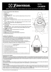
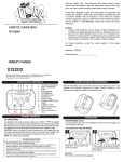
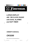
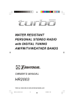
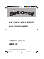
AM / FM CLOCK RADIO
with TELEPHONE
OWNER'S MANUAL
GP816
Visit our web site at www.emersonradio.com
GP816_ib072502.p65
19
25/7/2002, 11:38
WARNI NG
TO PREVENT FIRE OR SHOCK HAZARD, DO NOT USE THIS PLUG WITH AN
EXTENSION CORD, RECEPTACLE OR OTHER OUTLET UNLESS THE BLADES
CAN BE FULLY INSERTED TO PREVENT BLADE EXPOSURE. TO PREVENT FIRE
OR SHOCK HAZARD, DO NOT EXPOSE THIS APPLIANCE TO RAIN OR MOISTURE.
W AR N I N G
RISK OF ELECTRIC SHOCK
DO NOT OPEN
The lightning flash with arrowhead symbol, within an equilateral triangle is intented to
alert the user to the presence
of uninsulated ‘dangerous voltage’
within the product’s enclosure
that may be of sufficient
magnitude to constitute a risk
of electric shock to persons.
CAUTION: TO REDUCE THE
RISK OF ELECTRIC SHOCK
DO NOT REMOVE COVER
(OR BACK), NO USER
SERVICEABLE PARTS INSIDE
REFER SERVICING TO
QUALIFIED SERVICE
PERSONNEL.
!
The exclamation point within
an equilateral triangle is intended to alert the user to
the presence of important
operating and maintenance
(ser vi ci ng) instr ucti ons in
the liter ature accompanying the appl iance.
IMPORTANT SAFETY INSTRUCTIONS
When using your telephone equipment, basic safety precautions should always be
followed to reduce the risk of fire, electric shock and injury to persons, including the
following:
1.) Read these instructions.
2.) Keep these instructions.
3.) Heed all warnings.
4.) Follow all instructions.
5.) Do not use this product near water, for example, near a bath tub, wash bowl,
kitchen sink, or laundry tub, in a wet basement, or near a swimming pool.
6.) Cleaning. Unplug this product from the wall outlet before cleaning. Do not use
liquid cleaners or aerosol cleaners. Use a damp cloth for cleaning.
7.) Do not block any ventilation openings. Install in accordance with the
manufacturer’s instructions.
8.) Do not install near any heat sources such as radiators, heat registers, stoves,
or other apparatus (including amplifiers) that produce heat.
9.) Do not defeat the safety purpose of the polarized or grounding-type plug. A
polarized plug has two blades with one wider than the other. A grounding type
plug has two blades and a third grounding prong. The wide blade or the third
prong are provided for your safety. If the provided plug does not fit into your
outlet, consult an electrician for replacement of the obsolete outlet.
10.) Protect the power cord from being walked on or pinched particularly at plugs,
convenience receptacles, and the point where they exit from the apparatus.
1
GP816_ib072502.p65
1
25/7/2002, 11:38
11.) Only use attachments / accessories specified by the manufacturer.
12.) Unplug this apparatus during lightning storms or when unused for long periods
of time.
13.) Refer all servicing to qualified service personnel. Servicing is required when
the apparatus has been damaged in any way, such as power-supply cord or
plug is damaged, liquid has been spilled or objects have fallen into the
apparatus, the apparatus has been exposed to rain or moisture, does not
operate normally, or has been dropped. When the product exhibits a distinct
change in performance – this indicates a need for service.
14.) This appliance shall not be exposed to dripping or splashing water and no
object filled with liquids such as vases shall be placed on the apparatus.
15.) Do not overload wall outlet. Use only power source as indicated.
16.) Use replacement parts as specified by the manufacturer.
17.) The product may be mounted to a wall only if recommended by the manufacturer.
18.) Upon completion of any service or repairs to this product, ask the service
technician to perform safety checks.
19.) Avoid using a telephone (other than a cordless type) during an electrical storm.
There may be a remote risk of electric shock from lightning.
20.) Do not use the telephone to report a gas leak in the vicinity of the leak.
21.) Power Lines – An outside antenna system should not be located in the vicinity
of overhead power lines or other electric light or power circuits, or where it can
fall into such power lines or circuits. When installing an outside antenna system,
extreme care should be taken to keep from touching such power lines or
circuits as contact with them might be fatal.
22.) Object and Liquid Entry – Never push objects of any kind into this product
through openings as they may touch dangerous voltage points or short-out
parts that could result in a fire or electric shock. Never spill liquid of any kind
on the product.
23.) Power Sources – This product should be operated only from the type of power
source indicated on the marking label. If you are not sure of the type of power
supply to your home, consult your product dealer or local power company. For
products intended to operate from battery power, or other sources, refer to
the operating instruction.
SAVE THESE INSTRUCTIONS
2
GP816_ib072502.p65
2
25/7/2002, 11:38
IMPORTANT NOTES
• Before turning on the power, make
certain that the power cord is properly
installed.
• Avoid installing this unit in places
exposed to direct sunlight or close to
heat radiating appliances such as
electric heaters, on top of other stereo
equipment that radiates too much
heat, places lacking ventilation or
dusty areas, places subject to
constant vibration and/or humid or
moist areas.
• When moving the set, be sure to first
disconnect the power cord and
remove cords connected to other
equipment.
• Do not attempt to clean this unit with
chemical solvents as this might
damage the finish. Use a clean dry
cloth.
• Operate controls and switches as
described in the manual.
FCC INFORMATION
This equipment has been tested and found to comply with the limits for a Class B
digital device, pursuant to Part 15 of the FCC Rules. These limits are designed to
provide reasonable protection against harmful interference in a residential
installation. This equipment generates, uses, and can radiate radio frequency energy
and, if not installed and used in accordance with the instructions, may cause harmful
interference to radio communications. However, there is no guarantee that
interference will not occur in a particular installation. If this equipment does cause
harmful interference to radio or television reception, which can be determined by
turning the equipment off and on, the user is encouraged to try to correct the
interference by one or more of the following measures:
• Re-orient or re-locate the receiving antenna.
• Increase the separation between the equipment and receiver.
• Connect the equipment into an outlet on a circuit different from that to which
the receiver is connected.
• Consult the dealer or an experienced radio/TV technician for help.
This device complies with Part 15 of the FCC Rules. Operation is subject to the
following two conditions:
(1) This device may not cause harmful interference, and
(2) This device must accept any interference received, including interference
that may cause undesired operation.
3
GP816_ib072502.p65
3
25/7/2002, 11:38
FCC wants you to know
This equipment complied with part 68 of the FCC rules and ACTA technical
requirements. On the bottom of the base of this equipment is a label that contains,
among other information, the FCC Registration Number and Ringer Equivalence
Number (REN) for this equipment. You must, upon request, provide this information
to your telephone company.
The USOC number of the registration jack for the equipment is RJ11C.
The FCC compliant telephone cord and modular plug is provided with this
equipment. This equipment is designed to be connected to the telephone network
or premises wiring using a compatible modular jack which is TIA/EIA-IS-968
complaint.
If your telephone equipment caused harm to the telephone network, the telephone
company may discontinue your service temporarily. If possible, they will notify you
in advance. But, if advance notice isn’t practical, you will be notified as soon as
possible. You will be informed of your right to file a complaint with the FCC.
Your telephone company may make changes in its facilities, equipment, operations
or procedures that could affect the proper functioning of your equipment. If they
do, you will be notified in advance to give you an opportunity to maintain
uninterrupted telephone service. If you experience trouble with this telephone
equipment, the telephone company may ask that you disconnect this equipment
from the network until the problem has been corrected or until you are sure that
the equipment is not malfunctioning.
This equipment cannot be used on telephone company provided coin service.
Connection to Party Line Service is subject to state tariffs.
This equipment is hearing aid compatible.
Warnings:
• Any changes or modifications not expressly approved by the party responsible
for compliance could void the user’s authority to operate the equipment.
• When your telephone is not in use, make sure the handset is engaged into the
base unit.
• If it is determined that your telephone is malfunctioning, the FCC required that
it be disconnected from the modular outlet until the problem has been corrected.
Ringer Equivalence Number (REN)
The Ringer Equivalence Number is used to determine how many devices can be
connected to your home telephone line. The REN of this unit is 0.8B. The total
REN of all the devices connected to your line should not exceed 5.0.
If you exceed this total then one or more of the devices may not ring when a call is
received.
4
GP816_ib072502.p65
4
25/7/2002, 11:38
Thank you for purchasing the Girlpower AM/FM Clock Radio with Telephone from
Emerson. This unique product has been designed to provide you with many years
of exceptional performance with a minimum of care and maintenance.
Please review the contents of the instruction manual completely and carefully before
operating your unit. All of the functions and operations of the unit are fully explained
in the manual to enable you to gain the maximum benefit out of all the great product
features.
The serial number of your unit can be found at bottom of cabinet. For future
reference, we suggest that you record the serial number in the space provided
below.
Model No. GP816
Serial Number:
PREPARATION FOR USE
UNPACKING AND SET UP
• This carton contains the clock radio, the telephone handset, a modular straight
cord to connect the clock radio to your telephone wall jack, and a coiled cord
to connect the handset to the clock radio. Be sure to carefully remove all of the
components from the carton. We suggest you save the carton and packing
materials if possible in case it ever becomes necessary to return your unit for
service
• Remove any descriptive labels from the front or top of the cabinet. Do not
remove any labels from the back or bottom of the cabinet.
5
GP816_ib072502.p65
5
25/7/2002, 11:38
Battery Back Up
This unit has a battery back up system that will maintain the time and alarm settings
in the event of a temporary power interruption. The battery back up system requires
one 9-Volt battery, not included. We suggest using only a well known brand of
alkaline battery for longest life and best performance
The back up battery compartment is located on the back of the cabinet.
9 Volt
Battery
OPEN
Press down on the tab to open and remove the battery door. Attach the 9V battery
to the battery terminal strap (it can only be attached one way), insert the battery
into the battery compartment, and replace the battery door.
If the power is interrupted the clock display will go off, but the back up battery will
maintain both the time and the alarm settings in memory. When power is restored
the display will come on again and the time and alarm settings will be correct.
Do not dispose of batteries in a fire. They may explode. Check with local
codes for possible special disposal instructions.
Power Failure Indicator
If the power is interrupted and the battery is exhausted, or there is no battery in the
compartment, the time and alarm settings will be lost. When power is restored the
display will start flashing “12:00 AM”. This is your indication that the time display is
incorrect and needs to be reset.
IMPORTANT:
After resetting the time display make sure that you also recheck and adjust the
wake up time as well.
6
GP816_ib072502.p65
6
25/7/2002, 11:38
AC OPERATION
This product is designed to operate on normal 120V 60Hz AC only. Connecting
this system to any other power supply could result in damage to the unit which is
not covered by your warranty. You will note that this system is equipped with a
polarized AC power plug having one blade wider than the other. This is a safety
feature. If this plug does not fit into
your existing AC outlet, do not try to
defeat this safety feature by filing the
wide blade to make it fit into your
outlet. If this plug will not fit into your
AC Outlet
outlet, you probably have an outdated non-polarized AC outlet. You
AC Plug
should have your outlet changed by
a qualified licensed electrician.
Telephone Connections
Connect one end of the straight cord to the jack marked “TEL LINE” on the back
cabinet, and the other end to your telephone wall jack. If your telephone wall jack is
the older 4 pin type you will need to purchase a 4 pin to modular adapter plug,
available at most electronics stores and home improvement centers.
Standard Jack
4 Prong Jack
Hand Set
Straight Cord
Back Cabinet
Coiled Cord
AC Cord
Connect one end of the coiled cord to the jack on the telephone handset and the
other end to the jack on the back of the cabinet.
Placement
The unit must be placed in a location that is accessible to both a 120V 60Hz AC
outlet and a telephone wall jack. If necessary you may purchase a longer telephone
line cord wherever telephone accessories are sold.
7
GP816_ib072502.p65
7
25/7/2002, 11:38
LOCATION OF CONTROLS AND INDICATORS
5
4
3
6
2
1
8
9
7
23
24
22
21
14
20
13
15
16
12
11
17
18
25
26
27
19
10
28
1.) DIMMER (HIGH/LOW) Switch.
14.) Battery Compartment (Back of Unit).
2.) AM/FM Dial Scale and Pointer.
15.) Radio/Alarm Shut Off Switch.
16.) HOUR Button.
3.) ALARM Switch.
(OFF/RADIO/BUZZER)
17.) MINUTE Button.
4.) ALARM Indicator.
18.) RADIO ON Button.
5.) AM Indicator.
19.) Phone Line Cord Jack.
6.) Clock Display.
20.) RINGER (OFF/LO/HI) Switch.
7.) BAND (FM/AM) Switch.
21.) VOL. (L/M/H) Switch.
8.) TUNING Control.
22.) Keypad.
9.) VOLUME Control.
23.) Earpiece
24.) Hook Switch.
10.) SNOOZE Button.
(SLEEP OFF/RADIO OFF)
25.) TONE/PULSE Switch.
11.) SLEEP ON Button.
26.) REDIAL Button.
12.) ALARM SET/RESET Button.
27.) Mic.
13.) CLOCK SET Button.
28.) Phone Line Cord.
8
GP816_ib072502.p65
8
25/7/2002, 11:38
OPERATING INSTRUCTIONS
TELEPHONE FUNCTIONS
Automatic Radio Muting
If you are listening to the radio when the telephone rings it is not necessary to shut
off the radio manually. The Automatic Radio Muting circuit will shut the radio off
automatically as soon as you pick up the telephone handset. When you replace the
handset in the cradle the radio comes on again.
Telephone RINGER Switch
Set this switch to the “HI” or “LO” position to adjust the electronic ringer volume
level. If this switch is set to the “OFF” position the telephone will not ring when an
incoming call is received.
TONE/PULSE Selector
Set this switch to TONE or PULSE to match the type of dialing service provided by
your local phone company. If you do not know what type service you have set the
switch to TONE and try to make a call. If the call does not go through you probably
have Pulse dialing service. In that case set the switch to the PULSE position.
Speaker Volume Control
Set this VOL. switch to L (Low), M (Medium), or H (High) to adjust the telephone
earpiece volume to the most comfortable level.
Making A Call
Lift the handset and listen for a dial tone. If the radio was playing it will shut off
automatically. Dial the number on the keypad as usual. When finished, return the
handset to the cradle. The radio will turn on automatically if necessary.
9
GP816_ib072502.p65
9
25/7/2002, 11:38
Receiving A Call
Note:
The RINGER Switch must be in either the “HI” or “LO” position to receive a call.
When the phone rings lift the handset. The radio will shut off automatically. The
radio will turn on again when the handset is returned to its cradle.
Last Number Redial
If you dial a number and get a busy signal it is not necessary to redial the entire
number again. Just press the REDIAL button and the last number you called will
be redialed automatically.
Note: If the telephone line cord is disconnected from the wall jack the redial memory
will be erased after approximately one hour.
Hook Switch/Flash Button
The Hook Switch also functions as a Flash Button if you have Call Waiting service
from your local phone company. If you are on a call and you hear the ‘click’signal
which indicates that another call is waiting, press the Hook Switch momentarily to
access the second call. Press again to return to the original call.
10
GP816_ib072502.p65
10
25/7/2002, 11:38
CLOCK RADIO FUNCTIONS
Setting The Time Of Day
Note: The first time that the power cord is connected to the AC outlet the display
will begin flashing “12:00 AM”. This flashing display is your indication that the time
is incorrect and needs to be reset. The display will stop flashing when you begin to
adjust the time.
1.) Press and hold the CLOCK SET and HOUR buttons together to adjust the
hours. Release the buttons when the display shows the correct hour.
Note: Be sure to observe the AM indicator to set the hour correctly for AM or
PM. If the AM indicator is ‘On’, the hour displayed is AM. If the AM indicator is
‘Off’the hour displayed if PM.
2.) Press and hold the CLOCK SET and MINUTE buttons together to adjust the
minutes. Release the buttons when the display shows the correct time.
Setting The Wake Up Time
1.) Press and hold the ALARM SET/RESET and HOUR buttons together to set
the correct wake up hour.
NOTE: Be sure to observe the AM indicator to set the hour correctly for AM or
PM. If the AM indicator is ‘On’, the wake up hour displayed is AM. If the AM
indicator is ‘Off’the wake up hour displayed if PM.
2.) Press and hold the ALARM SET/RESET and MINUTE buttons together to
adjust the wake up minutes. Release the buttons when the display shows the
correct wake up time.
To check the Wake Up Time setting at any time simply press the ALARM SET/
RESET button. The display will change from Time Of Day to Wake Up Time as
long as the button is depressed.
11
GP816_ib072502.p65
11
25/7/2002, 11:38
LISTENING TO THE RADIO
Note: The telephone handset must be properly positioned in the cradle or the
radio will not operate.
1.) Press the RADIO ON button.
2.) Set the BAND selector to AM or FM.
3.) Rotate the TUNING control to select the desired station.
4.) Adjust the VOLUME control as desired.
5.) When you are finished listening press the SNOOZE (RADIO OFF) button.
Antenna Information
FM
The FM antenna is built in to the AC power cord. For best FM reception the AC
cord must be extended to its full length.
AM
The AM bar antenna is inside the radio cabinet. If AM reception is weak try turning
the cabinet slightly until reception improves. In extreme reception conditions you
may have to move the radio to a different location.
12
GP816_ib072502.p65
12
25/7/2002, 11:38
ALARM OPERATION
Note: Press the ALARM SET/RESET button to confirm the wake up time is set
correctly. Adjust if necessary.
Wake To Music
1.) Turn the radio ‘On’and select the station and volume level for wake up, then
turn the radio ‘Off’again.
2.) Set the ALARM selector to ‘RADIO’. The ALARM indicator will come ‘On’.
3.) At the selected Wake Up Time the radio will turn ‘On’automatically. It will play
for 1 hour and 59 minutes then shut off and reset itself for the following day.
• To stop the radio sooner, press the ALARM SET/RESET button. The radio
stops immediately and the alarm resets for the following day.
• To cancel the alarm completely set the ALARM selector to ‘OFF’. The Alarm
indicator goes ‘Off’. The radio stops and the alarm is canceled. It will not come
on again while the ALARM selector is in the ‘OFF’position.
Wake To Buzzer
1.) Set the ALARM selector to ‘BUZZER’. The Alarm indicator will come ‘On’.
2.) At the selected Wake Up Time the buzzer will sound. It will continue for 1 hour
and 59 minutes and then shut off and reset itself for the following day.
• To stop the buzzer sooner, press the ALARM SET/RESET button. The buzzer
stops immediately and the alarm resets for the following day.
• To cancel the alarm completely set the ALARM selector to ‘OFF’. The Alarm
indicator goes ‘Off’. The buzzer stops and the alarm is canceled. It will not
come on again while the ALARM selector is in the ‘OFF’position.
13
GP816_ib072502.p65
13
25/7/2002, 11:38
Snooze/Repeat Alarm
For a few extra minutes sleep after the alarm turns on in the morning press the
SNOOZE bar. The radio or buzzer alarm stops for approximately 9 minutes and
then turns on again. Snooze operation may be repeated several times if desired.
Sleep To Music Timer
You can set the sleep timer to operate the radio for up to 1 hour and 59 minutes
and then shut off automatically.
1.) Press the SLEEP ON button to start the Sleep Timer at 59 minutes. The radio
will turn on. Select the station and adjust the volume as desired. After 59
minutes the radio will shut off automatically.
2.) To adjust the Sleep Time downward from 59 minutes press and hold the SLEEP
ON button and the MINUTE button together. The display will count down from
59 minutes. Release the buttons when the display shows the desired Sleep
Time.
3.) To add one hour to the sleep time press the SLEEP ON and the HOUR button
together.
IMPORTANT: Remember that the station and volume level you select for Sleep
Timer operation is the same station and volume level you will hear when you Wake
To Radio the following morning.
DISPLAY DIMMER CONTROL
To reduce the brightness of the clock display set the DIMMER switch to the ‘LOW’
position.
14
GP816_ib072502.p65
14
25/7/2002, 11:38
CARE AND MAINTENANCE
CLEANING THE UNIT
• To prevent fire or shock hazard, disconnect your unit from the AC power source
when cleaning.
• If the cabinet becomes dusty wipe it with a soft dry dust cloth. Do not use any
wax or polish sprays on the cabinet.
• If the cabinet becomes dirty or smudged with fingerprints it may be cleaned
with a soft cloth slightly dampened with a mild soap and water solution. Never
use abrasive cloths or polishes as these will mar the finish of your unit.
CAUTION:
Never allow any water or other liquids to get inside the unit while cleaning.
TO F IND T HE L O CAT I O N A ND P HO NE
NUMBER OF YOUR NEAREST SERVICE
CENTER PERMITTED TO PERFORM
WARRANTY...
SERVICE
CALL TOLL FREE: 1-800-695-0098
FOR ADDITIONAL SET-UP OR OPERATING ASSISTANCE
PLEASE CALL:
1-800-898-9020
FOR CUSTOMER SERVICE,PLEASE WRITE TO:
Emerson Radio Corp.
Consumer Affairs Dept.
1901 Diplomat Drive,
Farmers Branch, TX 75234
15
GP816_ib072502.p65
15
25/7/2002, 11:38
TROUBLESHOOTING GUIDE
Should this unit exhibit a problem, check the following before seeking service.
Symptom
Radio
Possible Cause
Solution
Noise or sound
distorted on AM or FM
Station not tuned properly for
AM or FM.
Retune the AM or FM
broadcast station.
broadcasts.
FM: AC cord is not extended.
Extend the AC cord for best
reception.
AM: The bar antenna is not
positioned correctly.
Reposition the unit until
best reception is obtained.
AM or FM, no sound.
Handset is not placed correctly Place the handset correctly.
on the base
Volume at minimum.
Increase Volume.
Phone does not ring.
RINGER switch is set to OFF
position.
Set RINGER switch to LO
or HI position.
Telephone does not
work.
Handset is placed incorrectly.
Line cord or plug loose.
Place the handset correctly.
Check and secure all
Phone number can’t be
TONE/PULSE switch is set
connections.
Set the TONE/PULSE
dialed.
CLOCK
incorrectly.
switch to correct position.
Display flashes.
Back up battery weak or loose. Secure or change new
battery. Reset the clock.
Alarm does not sound.
ALARM switch is set to OFF
position.
Set ALARM switch to
RADIO or BUZZER position.
Times are not set correctly.
Set correct times and make
AM/PM setting.
No AC power.
Check AC cord and AC
outlet.
TELEPHONE
No clock display.
16
GP816_ib072502.p65
16
25/7/2002, 11:38
LIMITED WARRANTY
Emerson Radio Corp. warrants manufacturing defects in original material, including
original parts and workmanship, under normal use and conditions, for a period of
ninety (90) days from the date of original purchase in the U.S. With your dated
proof of purchase, we will provide repair service at no charge for labor and parts
at an authorized Depot Repair Facility, or replace the product in our discretion.
For repair or replacement, pack your unit in a padded box, enclose your check or
money order payable to Emerson Radio Corp. in the amount of $5.00 (not required
by California residents) to cover shipping and handling costs, and enclose a copy
of your proof of purchase. Send your unit to:
Emerson Radio Corp.
1901 Diplomat Drive.
Farmers Branch, TX 75234.
This warranty does not cover damage from negligence, misuse, abuse, accident,
failure to follow operating instructions, commercial use, rental, repairs by an
unauthorized facility, or products purchased, used, serviced or damaged outside
of the United States.
THIS WARRANTY GIVES YOU SPECIFIC LEGAL RIGHTS, AND YOU MAY
ALSO HAVE OTHER RIGHTS WHICH VARY FROM STATE TO STATE.
AU898H
17
GP816_ib072502.p65
17
25/7/2002, 11:38
BY
EMERSON
Part No. : 21-2033
207-01
GP816_ib072502.p65
Printed in China
18
25/7/2002, 11:38