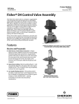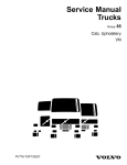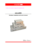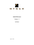
1
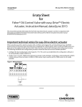
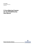
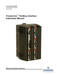
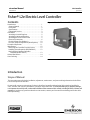
Instruction Manual L2e Controller D103531X012 June 2014 Fisherr L2e Electric Level Controller Contents Introduction . . . . . . . . . . . . . . . . . . . . . . . . . . . . . . . . . 1 Scope of Manual . . . . . . . . . . . . . . . . . . . . . . . . . . . . . 1 Description . . . . . . . . . . . . . . . . . . . . . . . . . . . . . . . . . 2 Specifications . . . . . . . . . . . . . . . . . . . . . . . . . . . . . . . 2 Educational Services . . . . . . . . . . . . . . . . . . . . . . . . . 2 Installation . . . . . . . . . . . . . . . . . . . . . . . . . . . . . . . . . . 4 Attaching a Vertical Displacer . . . . . . . . . . . . . . . . . . 5 Attaching a Horizontal Displacer . . . . . . . . . . . . . . . 5 Attaching the Sensor to the Vessel . . . . . . . . . . . . . 5 Electrical Connections . . . . . . . . . . . . . . . . . . . . . . . . 6 L2e Initial Setup (Dry Displacer) . . . . . . . . . . . . . . . 10 L2e Zero and Span Adjustment (Wet Displacer) . . 10 Principle of Operation . . . . . . . . . . . . . . . . . . . . . . . . 11 Maintenance . . . . . . . . . . . . . . . . . . . . . . . . . . . . . . . . 12 Removing the Controller From the Sensor . . . . . . 12 Installing Sensor Repair Kit (RL2SENSX012) . . . . . 12 Replacing the Complete Controller Assembly (RL2ECTLRX12) . . . . . . . . . . . . . . . . . . 13 Related Documents . . . . . . . . . . . . . . . . . . . . . . . . . . 14 Parts Ordering . . . . . . . . . . . . . . . . . . . . . . . . . . . . . . . 14 Figure 1. Fisher L2e Electric Level Controller X0660 Introduction Scope of Manual This instruction manual includes installation, adjustment, maintenance, and parts ordering information for the Fisher L2e electric liquid level controller. Do not install, operate or maintain an L2e electric liquid level controller without being fully trained and qualified in valve, actuator, and accessory installation, operation, and maintenance. To avoid personal injury or property damage, it is important to carefully read, understand and follow all the contents of this manual, including all safety cautions and warnings. If you have any questions about these instructions, contact your Emerson Process Management sales office before proceeding. www.Fisher.com L2e Controller June 2014 Instruction Manual D103531X012 Description The L2e electric liquid level differential gap on-off controller uses a displacement type sensor to detect liquid level or the interface of two liquids of different specific gravities. The L2e controls the lower trip point (zero) that closes the dump valve, allowing the vessel to fill to the upper trip point. Once the upper trip point is reached, the dump valve opens to drain the fluid down to the zero or lower trip point. The difference between the upper trip point and the zero or lower trip point is called differential gap or DG. The L2e operates as a two position (on-off) controller. These controllers use a single pole double throw (SPDT) dry contact electric switch to provide differential gap (DG) control or liquid monitoring. The controller can be used to provide an electric control signal to an electrically actuated control valve. Unless otherwise noted, all NACE references are to NACE MR01752002. Specifications Specifications for the controller and sensor are listed in table 1. Educational Services For information on available courses for L2e electric liquid level controllers, as well as a variety of other products, contact: Emerson Process Management Educational Services - Registration Phone: +1-641-754-3771 or +1-800-338-8158 [email protected] http://www.emersonprocess.com/education 2 Instruction Manual L2e Controller D103531X012 June 2014 Table 1. Specifications Displacer Sizes J 48 X 305 mm, 541 cm3 (17/8 X 12 inches, 33 in3) J 76 X 152 mm, 688 cm3 (3 X 6 inches, 42 in3) Available Configurations Controller: Differential gap (DG) electric control action with intuitive Zero and Span Adjustments in SPDT dry contact configuration (refer to page 2 for differential gap description) Sensor: Displacertype liquid level sensor for mounting to side of vessel Maximum Displacer Insertion Length(2), Horizontal or Vertical 1-7/8 x 12 Displacer with one 6-inch extension (optional use) 3 x 6 Displacer with one 3-inch extension (optional use) Input Signal Type: Liquid level or liquidtoliquid interface Displacer Material and Maximum Sensor Working Pressure(3) PVC Displacer: Consistent with CL1500 pressure temperature ratings per ASME B16.34 up to maximum pressure of 258.5 bar (3750 psig). For PED (97/23/EC) maximum pressure limited to 200 bar (2900 psig). S31603 SST Displacer: CL600 pressure temperature ratings per ASME B16.34 up to maximum pressure of 99.3 bar (1440 psig) Note: For slipon flange connection, maximum sensor working pressure must be consistent with the flange ratings Level Change Required for Full Change in State of Output: 5.0 to 559 mm (0.2 to 22 inches) Vessel level DG is dependant on factors such as valve sizing, actuator speed, rate, liquid out flow, and vessel size. Contact your Emerson Process Management sales office for Fisher Electric Level Loop performance optimization. Specific Gravity Limits Minimum SG: 0.15 Maximum SG PVC Displacer: 1.3 SST Displacer: 1.1 Operative Ambient Temperature Limits(3) Controller: 40 to 75°C (40 to 167°F) Electrical Rating (Output) J easy-Drive™ actuator application: 7 mA@5 VDC J Other applications: 1 amp resistive, 0.5 amp inductive/28 VDC Operative Process Temperature Limits(3) Sensor: J PVC Displacer: -18 to 71°C (0 to 160°F) J S31603 SST Displacer: 40 to 204°C (40 to 400°F) Note: Use with easy-Drive after first being used in other high power application is not recommended. Power Consumption Construction Materials Controller Case and Cover: Marine grade aluminum Switch: Stainless steel Span Levers: Stainless steel Springs: Stainless steel Sensor Sensor Body: LCC ORings: Fluorocarbon Pivot Assembly: Stainless steel Displacer: J Polyvinylchloride (PVC) or J S31603 SST Sensor Spring: Stainless steel Switch consumes no power to operate, so it has no current leakage or voltage drop Sensor to Vessel Connection J 2 NPT threaded or J NPS 2 CL150 through 1500 slipon flange connection(1) Controller Connection Electrical 1/2-14 NPT external conduit connection with 18 inches of 18 AWG lead wires, located at the bottom of the case -continued- 3 L2e Controller Instruction Manual D103531X012 June 2014 Table 1. Specifications (continued) Hazardous Area Classifications Available Switch Only cCSAus Explosion-proof Class I Division 1, Groups ABCD Dust Ignition-proof Class II Division 1, Groups EFG Dual Seal ATEX II 2 GD Flameproof Ex d IIC T6 (Ta=40°C to + 75°C) Dust Ex tb IIIC T85°C Db IP6X (Ta = 40° to +75°C) 1 A Max IECEx Flameproof Ex d IIC T6 (Ta=40°C to + 75°C) Dust Ex tb IIIC T85°C Db IP6X (Ta = 40° to +75°C) 1 A Max Canadian Registration (CRN) The L2e utilizes the same sensor unit pressure component as the L2 pneumatic controller version. Refer to the L2 CRN which is deemed applicable to the L2e. Declaration of SEP Fisher Controls International LLC declares this product to be in compliance with Article 3 paragraph 3 of the Pressure Equipment Directive (PED) 97 / 23 / EC. It was designed and manufactured in accordance with Sound Engineering Practice (SEP) and cannot bear the CE marking related to PED compliance. However, the product may bear the CE marking to indicate compliance with other applicable European Community Directives. NOTE: Specialized instrument terms are defined in ANSI/ISA Standard 51.1 Process Instrument Terminology. 1. Converting from a threaded NPT connection to a flange connection is to be done by the end-user. Refer to Converting a Threaded NPT Connection to a Flange Connection instruction Manual Supplement (D103277X012), available at www.Fisher.com or from your Emerson Process Management sales office. 2. Maximum span setting with 1 7/8 x 12 inch horizontal displacer plus 6 inch extension is not recommended due to potentially insufficient zero adjustment. 3. The pressure and temperature limits in this document and any applicable code limitations should not be exceeded. Installation WARNING Always wear protective clothing, gloves, and eyewear when performing any installation operations to avoid personal injury. To avoid personal injury or property damage caused by the sudden release of process fluid, be certain the service conditions do not exceed the sensor pressure limits. Use pressurelimiting or pressurerelieving devices to prevent service conditions from exceeding these limits. Check with your process or safety engineer for any additional measures that must be taken to protect against process media. If installing this into an existing application, also refer to the WARNING at the beginning of the Maintenance section of this instruction manual. CAUTION If the L2e electric level controller is installed on a vessel that is to be shipped to a different location (e.g. skid mounted units), remove the displacer and displacer rod extensions before shipment. Failure to do so could result in damage to the instrument and or the displacer rod due to vibration and impact loading during shipment. After the vessel is installed at its final location, reassemble the displacer and displacer rod extension. Note Use with easyDrive electric actuator after first being used in other high power application is not recommended. 4 Instruction Manual L2e Controller D103531X012 June 2014 1. Be sure there are no obstructions inside the vessel that will interfere with displacer installation or operation. 2. Provide the appropriate connection in the vessel wall to match the sensor connection. Locate the vessel wall connection such that the displacer will be at the desired control level. Attaching a Vertical Displacer Refer to figure 9 for part locations. 1. Thread jam nut (key 63) all the way onto the threaded portion of the universal joint assembly (key 69). 2. Thread the displacer (key 81) all the way onto the threaded portion of the universal joint assembly. 3. Tighten the jam nut against the displacer. Attaching a Horizontal Displacer Refer to figure 9 for part locations. 1. Thread the displacer (key 81) all the way onto the displacer rod (key 64) or extension (key 82) and tighten. Attaching the Sensor to the Vessel Insert the displacer end of the L2e sensor into the vessel connection and tighten enough to seal the threads. If necessary, loosen or tighten slightly to obtain the horizontal orientation shown in figure 2. Make sure that the controller case is level. CAUTION The displacer rod (key 64) is not a handle. Grasp sensor body or controller housing to lift and carry to avoid internal component damage. Figure 2. Sensor Orientation CORRECT CONTROLLER MOUNTING HOLE ORIENTATION WHEN MOUNTED ON VESSEL A6639 5 Instruction Manual L2e Controller D103531X012 June 2014 Electrical Connections WARNING For explosionproof applications, disconnect power before installing, servicing or removing electrical components. Personal injury or property damage from fire or explosion may result if power is not disconnected. Select junction boxes, wiring and/or cable glands that are rated for the environment of use (such as hazardous location, ingress protection, and temperature). Failure to use properly rated electrical hardware wiring and/or cable glands can result in personal injury or property damage from fire or explosion. Wiring connections must be in accordance with local, regional, and national codes for any given hazardous area approval. Failure to follow the local, regional, and national codes could result in personal injury or property damage from fire or explosion. An electrical 1/2-14 NPT conduit connection with 18 inches of 18 AWG lead wires is located at the bottom of the case. The conduit connection is integral to the body of the switch. The action of the controller is such that rising level will cause the Normally Closed (N/C) contacts to close and the Normally Open (N/O) contacts to open. Falling level causes the opposite action. Connect L2e electrical wires as shown in table 2. To reverse the action refer to table 2 and reverse wiring for normally open and normally closed. Table 2. L2e Electrical Wire Configuration Wire Color SPDT Action Red Normally Closed Brown Common Blue Normally Open Green Ground 6 Instruction Manual L2e Controller D103531X012 June 2014 Wiring Configurations There are two recommended wiring configurations depending on the preferred site solution and approach to electric level control; a direct connection to the easy-Drive actuator, shown in figure 3 or a direct connection to the easy-Drive actuator and a remote monitor (figure 4 and 5). In these examples, the L2e is wired using a common and separate N/O or N/C contact. When implemented as suggested, these wiring configurations provide definitive level switch points and help reduce issues associated with single pole single throw contact switches, such as “bouncing” due to vibration or sloshing liquids in a vessel. Note Use with easyDrive electric actuator after first being used in other high power application is not recommended. Figure 3. Local Level Control with Direct Connection to easy-Drive Actuator without Remote Monitor REMOVE COVER TO ACCESS POWER AND CONTROL TERMINAL X0661 2 12/24 VDC POWER SUPPLY GREEN (GND) 1 BROWN RED BLUE OPEN CLOSE W9795-4 easy-Drive ACTUATOR WITH FISHER D3 CONTROL VALVE easy-Drive ACTUATOR POWER AND CONTROL TERMINAL 1 2 CONNECT GREEN WIRE TO ACTUATOR GROUND (NOT SHOWN) OPEN CONTACT (2) MAY BE LABELED N.O. AND CLOSE CONTACT (3) MAY BE LABLED N.C. 7 Instruction Manual L2e Controller D103531X012 June 2014 Figure 4. Local Level Loop Control with Direct Connect to easy-Drive Actuator with ROC809 Remote Monitor REMOVE COVER TO ACCESS POWER AND CONTROL TERMINAL 12/24 VDC POWER SUPPLY X0661 GREEN (GND) 2 1 BROWN RED BLUE BROWN BLUE RED OPEN CLOSE W9795-4 easy-Drive ACTUATOR POWER AND CONTROL TERMINAL ROC809 DI MODULE DISCRETE INPUT CONFIGURED FOR DRY CONTACT CLOSURE EXTERNALLY POWERED 1 2 8 CONNECT GREEN WIRE TO ACTUATOR GROUND (NOT SHOWN) OPEN CONTACT (2) MAY BE LABELED N.O. AND CLOSE CONTACT (3) MAY BE LABLED N.C. easy-Drive ACTUATOR WITH FISHER D3 CONTROL VALVE Instruction Manual L2e Controller D103531X012 June 2014 Figure 5. Local Level Loop Control with Direct Connect to easy-Drive Actuator with FloBoss 107 Remote Monitor REMOVE COVER TO ACCESS POWER AND CONTROL TERMINAL 12/24 VDC POWER SUPPLY X0661 GREEN (GND) 2 1 BROWN RED BLUE BLUE BROWN RED OPEN CLOSE W9795-4 easy-Drive ACTUATOR POWER AND CONTROL TERMINAL easy-Drive ACTUATOR WITH FISHER D3 CONTROL VALVE FloBoss 107 AI/DI MODULE OR FloBoss 107 DIs ON CPU MODULE'S OPTIONAL I/O ASSEMBLY DISCRETE INPUT CONFIGURED FOR DRY CONTACT CLOSURE EXTERNALLY POWERED 1 2 CONNECT GREEN WIRE TO ACTUATOR GROUND (NOT SHOWN) OPEN CONTACT (2) MAY BE LABELED N.O. AND CLOSE CONTACT (3) MAY BE LABLED N.C. 9 Instruction Manual L2e Controller D103531X012 June 2014 L2e Initial Setup (Dry Displacer) Refer to figure 6. 1. Move Span to minimum setting. 2. Move Zero down until the valve opens, or N/C contact (red to brown leads) closes. 3. Slowly move Zero up until valve closes, or N/C contact (red to brown leads) opens. L2e Zero and Span Adjustment (Wet Displacer) After initial setup (dry displacer) is complete, 1. Enable process flow into the vessel. 2. Move Zero and Span Adjustment for desired liquid zero position and level DG. 3. Tighten the Zero Adjustment hex nut (key 5), shown in figure 7, to lock the Zero setting. Note Scan the QR code shown in figure 6 or on the inside cover of the L2e for electric level loop field support. Figure 6. Initial Setup GG11109-C 10 Instruction Manual L2e Controller D103531X012 June 2014 Principle of Operation The operation of the L2e is based on Archimedes Principle, which states that a body immersed in a liquid will be buoyed up by a force equal to the weight displaced. The buoyant force and resultant movement of the displacer in the liquid is transmitted to the controller. As the buoyant force changes a proportional change in movement is seen by levers A and B (refer to figure 7). Levers A and B are arranged and connected by movable pivot or span adjustment so that the resultant movement between the plunger and the switch can be adjusted. For a given change in displacer movement the span adjustment will increase or decrease a proportional change in the plunger movement. As fluid level rises, the plunger moves away from the switch and vice versa. Figure 7. Fisher L2e Controller CONTROLLER MOUNTING SCREWS (KEY 24) LEVER A SPAN ADJUSTMENT DISPLACER ROD (KEY 64) LEVER B ZERO SPRING (KEY 7) SWITCH ZERO ADJUSTMENT ZERO ADJUSTMENT HEX NUT (KEY 5) GG10047 w/Displacer Rod PLUNGER FACTORY SET - DO NOT ADJUST 11 L2e Controller Instruction Manual June 2014 D103531X012 Maintenance Parts are subject to normal wear and must be inspected periodically and replaced as necessary. The frequency of parts inspection and replacement depends upon the severity of service conditions. When inspection or repairs are required, disassemble only those parts necessary to accomplish the task. WARNING Always wear protective clothing, gloves, and eyewear when performing any maintenance operations to avoid personal injury. To avoid personal injury or property damage caused by the release of pressure or process fluid, observe the following before starting maintenance: D Provide some temporary means of control for the process before taking the controller out of service. D Provide a means of containing the process fluid before removing any measurement devices from the process. D Vent any trapped process pressure. D Check with your process or safety engineer for any additional measures that must be taken to protect against process media. Removing the Controller From the Sensor Refer to figure 7 for key number locations unless otherwise indicated. 1. Disconnect power from any electrical source. 2. Slide the hook end of the zero spring (key 7) over and off the controller end of the displacer rod (key 64). 3. Remove the four controller mounting screws (key 24), and pull the controller straight away from the sensor. Installing Sensor Repair Kit (RL2SENSX012) Refer to figure 9 for key number locations unless otherwise indicated. Disassembly 1. Remove the controller from the sensor by following the procedure outlined in the previous section. 2. Remove the sensor from the vessel. 3. Unscrew the hex nut (key 67) and remove the spacer (key 66) and spring (key 68). After removing the spring, replace the spacer (key 66) and hex nut (key 67) on the displacer rod. From the displacer end, pull the displacer rod away from the sensor connection (key 65) to pull the pivot base (key 73) loose from the sensor connection. Remove the hex nut (key 67) to permit removing the displacer rod, pivot base, pivot body, and spacer from the sensor connection. 4. Slide the pivot base (key 73), retaining ring (key 76), antiextrusion ring (key 75), and Oring (key 74) off the displacer rod. Remove the Oring (key 77) and backup ring (key 78) from the pivot base. 12 Instruction Manual L2e Controller D103531X012 June 2014 Assembly WARNING Improper assembly of the Orings, anti-extrusion ring, and backup ring could result in Oring extrusion and permit leakage of process fluids. To avoid personal injury or property damage from leaking process fluid, be sure the Orings, antiextrusion ring and backup ring are assembled in the order shown in figure 9. 1. Place the pivot body (key 72) on the displacer rod (key 64) so that it is positioned as shown in figure 9. 2. Apply silicone sealant (key 79) to the O-ring (key 74) and slide onto the displacer rod assembly (key 64) with the antiextrusion ring (key 75) and retaining ring (key 76). Be sure the Oring, antiextrusion ring, and retaining ring are in the order shown in figure 9. Slide the pivot base onto the displacer rod so that the knife edges of the pivot body (key 72) engage the slots in the pivot base (key 73). 3. Apply silicone sealant (key 79) to the O-ring (key 77) and install with the backup ring (key 78) into the groove on the pivot base (key 73). Be sure the backup ring is on the process pressure side of the Oring as shown in figure 9. 4. Insert the displacer rod (key 64) into the vessel side of the sensor connection (key 65). 5. The pivot base must seat in the slots cast in the sensor connection. These slots will be horizontal when the sensor connection (key 65) is oriented as shown in figure 2. 6. To reduce the possibility of nicking the Oring key (77) on the pivot base, keep the displacer rod centered in the sensor connection as much as possible while pushing the pivot base into the sensor connection. Be sure the pivot base seats in the slots cast in the sensor connection. 7. Slide the spring (key 68) and spacer (key 66) onto the displacer rod and secure with the hex nut (key 67). Fully tighten the hex nut (key 67). 8. Examine the sensor to ensure that the two pivot knife edges are seated in the pivot base slots. 9. Install the sensor on the vessel. Replacing the Complete Controller Assembly (RL2ECTLRX12) Refer to figure 7 for key number locations unless otherwise indicated. 1. Disconnect power from any electrical source. 2. Slide the hook end of the zero spring (key 7) over and off the controller end of the displacer rod (key 64) 3. Remove the four controller mounting screws (key 24) and pull the controller straight away from the sensor. 4. Install the new controller assembly on the sensor. 5. Mount with the four screws (key 24). 6. Slide the hook end of the zero spring (key 7) on the controller end of the displacer rod (key 64). 7. Complete signal wiring hookup to easy-Drive electric actuator. 8. Perform the Initial Setup (Dry Displacer) and Zero and Span Adjustment procedures found on page 10. Note Use with easyDrive electric actuator after first being used in other high power application is not recommended. 13 Instruction Manual L2e Controller D103531X012 June 2014 Related Documents D Bulletin 34.2:L2e Fisher L2e Electric Level Controller (D103532X012) D Changing easy-Drive Electric Actuator On/Off Input Configuration from Single Dry Contact Control to Dual Dry Contact Control—Supplement to L2e Electric Level Controller Instruction Manual (D103987X012) D Converting a Threaded NPT Connection to a Flange Connection—Supplement to Fisher L2, L2e, and L2sj Liquid Level Controller Instruction Manuals (D103277X012) D Dimensions for NPS 2 CL150 through 1500 Slip On Flange Connections—Supplement to Fisher L2, L2e, and L2sj Liquid Level Controller Instruction Manuals (D103405X012) D Bulletin 51.2:D3 Fisher D3 Control Valve (D103269X012) D Fisher D3 Control Valve with easy-Drive Electric Actuator Instruction Manual (D103460X012) D Bulletin 51.2:D4 Fisher D3 Control Valve Assembly (D103039X012) D Fisher D4 Control Valve with easy-Drive Electric Actuator Instruction Manual (D103597X012) All documents are available from your Emerson Process Management sales office. Also visit our website at www.Fisher.com. Parts Ordering When corresponding with your Emerson Process Management sales office about this equipment, always mention the serial number of the controller. The serial number can be found on the nameplate. When ordering replacement parts, also specify the complete 11character part number of each part required as found in the following parts list. WARNING Use only genuine Fisher replacement parts. Components that are not supplied by Emerson Process Management should not, under any circumstances, be used in any Fisher instrument. Use of components not supplied by Emerson Process Management may void your warranty, might adversely affect the performance of the valve, and could cause personal injury or property damage. Kits Description Sensor Repair Kit Repair kit includes keys 74, 75, 76, 77, and 78 (fluorocarbon O‐rings, anti‐extrusion ring, retaining ring, and fluorocarbon backup ring) 14 Part Number RL2SENSX012 Description Controller Assembly Replacement Replacement kit includes complete controller assembly (figure 8) with mounting screws and gasket Part Number RL2ECTLRX12 Instruction Manual L2e Controller D103531X012 June 2014 Figure 8. Fisher L2e Electric Level Controller Assembly GG10047-E Parts List Key Note Note For part numbers not shown, contact your Emerson Process Management sales office. Keys 74, 75, 76, 77, and 78 are included in the Sensor Repair Kit. Description Part Number 74 75 76 77 78 O‐Ring, fluorocarbon Anti‐extrusion ring, PTFE Retaining ring, 304 SST O‐Ring fluorocarbon Backup ring, fluorocarbon Sensor (see figure 9) 79 Sealant, silicone (not furnished with sensor) 63 64 65 66 67 68 Hex jam nut, 316 SST Displacer rod, 17‐4 SST (17‐4PH SST) Sensor connection Spacer, 304 SST Hex jam nut, 316 SST Conical spring, 316 SST 81 Displacer, 1‐7/8x12‐inches PVC S31603 3x6-inches PVC GE16513X012 69 70 71 72 73 Universal Joint, 316 SST (vertical displacer only) Nameplate Drive screw, stainless steel Knife pivot body, CB7CU‐1 (17‐4PH SST) Knife pivot base, CF8M (316 SST) 82 Extension 3 inches 6 inches GE14958X012 12B2953X022 Key Description 89 12B2936X032 12B2956X032 NACE Label 15 Instruction Manual L2e Controller D103531X012 June 2014 Figure 9. Sensor VIEW B-B SCALE 2:1 A SECTION C-C SCALE 2:1 A B C j APPLY LUB/SEALANT C SECTION A-A GG12263-B Neither Emerson, Emerson Process Management, nor any of their affiliated entities assumes responsibility for the selection, use or maintenance of any product. Responsibility for proper selection, use, and maintenance of any product remains solely with the purchaser and end user. Fisher and easy-Drive are marks owned by one of the companies in the Emerson Process Management business unit of Emerson Electric Co. Emerson Process Management, Emerson, and the Emerson logo are trademarks and service marks of Emerson Electric Co. All other marks are the property of their respective owners. The contents of this publication are presented for informational purposes only, and while every effort has been made to ensure their accuracy, they are not to be construed as warranties or guarantees, express or implied, regarding the products or services described herein or their use or applicability. All sales are governed by our terms and conditions, which are available upon request. We reserve the right to modify or improve the designs or specifications of such products at any time without notice. Emerson Process Management Marshalltown, Iowa 50158 USA Sorocaba, 18087 Brazil Chatham, Kent ME4 4QZ UK Dubai, United Arab Emirates Singapore 128461 Singapore www.Fisher.com 16 E 2013, 2014 Fisher Controls International LLC. All rights reserved.