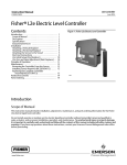
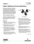
1
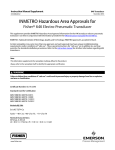
Product Bulletin
L2 Controller
34.2:L2
September 2013
D103034X012
Fisherr L2 Liquid Level Controller
The rugged Fisher L2 liquid level controller uses a
displacer type sensor to detect liquid level or the
interface of two liquids of different specific gravities.
This controller is ideal for controlling level on gas
separators and scrubbers. The reliability of the L2
design makes it well suited for liquid level applications
in natural gas production, compression, and
processing. The device delivers a pneumatic output
signal to a control/dump valve. The sensor uses a
threaded 2 NPT or an NPS 2 CL150 through 1500
slip-on flange connection to the vessel.
Features
n More Reliable Control—Two-stage proportional
relay with integral action provides more dependable
liquid level control.
n Snap-Acting or Throttling Control—One standard
controller available as either throttling or
snap-acting.
W8418-1
n Vibration Resistant Sensor Dynamics— O-ring
friction and process pressure sensitivity are
minimal. Performance stays constant with process
pressure changes and controller remains vibration
resistant.
n NACE Service Ready—Standard construction uses
materials that comply with the requirements of
NACE MR0175-2002.
n CL1500 Pressure Rating—Sensor assembly is
designed and specified for ASME B16.34 CL1500
service when using a Polyvinylchloride (PVC)
displacer. For PED (97/23/EC) maximum pressure is
limited to 200 bar (2900 psig).
n Field-Configurable Vertical or Horizontal
Displacer—Displacer may be adjusted in the field for
vertical or horizontal operation without additional
parts.
n Vent-Away Case—The ability to pipe away exhaust
permits using natural gas as the operating medium.
n Field-Reversible Output—The controller can be
adjusted in the field for direct or reverse action
without additional parts. The controller also has
adjustable gain sensitivity.
www.Fisher.com
n Easy Maintenance—Both the controller and the
sensor can be easily disassembled to inspect the
process seals and for maintenance.
Product Bulletin
L2 Controller
34.2:L2
September 2013
D103034X012
Specifications
Snap-Acting Controller: Any desired pressure
between 1.4 and 5.2 bar (20 and 50 psig) direct, and
1.4 and 2.4 bar (20 and 35 psig) reverse
Available Configurations
Controllers: Snap-acting or throttling
Sensor: Displacer-type liquid level sensor for
mounting to side of tank. Displacer travel is
transmitted to controller by pivotal movement of
displacer rod
Do not use supply pressure below 1.4 bar (20 psig)
Supply Pressure Medium
Air or natural gas(4)
Input Signal
Steady-State Air Consumption(5)
Type: Liquid level or liquid-to-liquid interface
Throttling Controller: ≤0.03 normal m3/hr (1.0 scfh)
at 1.4 bar (20 psig) supply pressure
Snap-Acting Controller: ≤0.03 normal m3/hr
(1.0 scfh) at 1.4 bar (20 psig) supply pressure or
≤0.04 normal m3/hr (1.5 scfh) at 2.4 bar (35 psig)
supply pressure in tripped condition; air consumption
increases during trip
Level Change Required for Full Change in Output
Signal in a 1.0 Specific Gravity Liquid, with 1.4 bar (20
psig) Supply Pressure, Direct Action, and Standard
1-7/8 X 12-Inch (48 x 305 mm) Vertical Displacer with
Standard Lever Arm Length:
Minimum Span Level
Change, mm (Inches)(1)
Maximum Span Level
Change, mm (Inches)(1)
Throttling
102 (4)
305 (12)
On-off
127 (5)
305 (12)
Snap-acting
13 (0.5)
20 (0.8)
Control Mode
Sensor to Vessel Connection
J 2 NPT threaded or J NPS 2 CL150 through 1500
slip-on flange connection(6)
Controller Connections
Supply: 1/4 NPT internal located on the bottom of the
case
Output: 1/4 NPT internal located on the top of the
case
Case Vent: 1/4 NPT internal with vent screen
assembly located on the back of the case
Minimum Specific Gravity(2)
Throttling Controller: Minimum specific gravity, or
specific gravity differential for interface applications,
is 0.1(3).
Snap-Acting Controller: Minimum specific gravity, or
specific gravity differential for interface applications,
is 0.1
Standard Displacer Size
48 x 305 mm, 541 cm3 (1-7/8 x 12 inches, 33 in3)
Output Signal
Maximum Displacer Insertion Length(7)
Pneumatic J on-off or J proportional pressure
signal
Ranges:
Throttling: J 0.2 to 1.0 bar (3 to 15 psig) or J 0.4 to
2.0 bar (6 to 30 psig)
On-Off: 0 (off) or full supply pressure (on)
Action: Field-reversible between direct (increasing
level increases output signal) and reverse (increasing
level decreases output signal)
Standard lever arm length plus one 6-inch extension,
horizontal or vertical
Displacer Material and Maximum Sensor Working
Pressure(8)
PVC Displacer: Consistent with CL1500 pressure
temperature ratings per ASME B16.34 up to
maximum pressure of 258.5 bar (3750 psig)
For PED (97/23/EC) maximum pressure limited to 200
bar (2900 psig)
Supply Pressure Requirements
S31603 SST Displacer: CL600 pressure temperature
ratings per ASME B16.34 up to maximum pressure of
99.3 bar (1440 psig)
Throttling Controller:
Throttling: 1.4 bar (20 psig) for 0.2 to 1.0 bar (3 to 15
psig) output signal and 2.4 bar (35 psig) for 0.4 to 2.0
bar (6 to 30 psig) output signal
On-Off: Any desired pressure between 1.4 and 3.4 bar
(20 and 50 psig)
Note: For slip-on flange connection, maximum sensor
working pressure must be consistent with the flange
ratings
-continued-
2
Product Bulletin
L2 Controller
34.2:L2
September 2013
D103034X012
Specifications (continued)
Displacer Material and Sensor Temperature
Limits(8)
PVC Displacer: -29 to 79_C (-20 to 175_F)
S31603 SST Displacer: -40 to 204_C (-40 to 400_F)
Operative Ambient Temperature Limits(8)
Controller: -29 to 71_C (-20 to 160_F)
Standard Supply, and Output Pressure Gauge
Indications
Triple scale gauges in 0 to 60 psig/0 to 0.4 MPa/
0 to 4.0 bar
Construction Materials
Controller:
Case and Cover: Marine grade aluminum
Relay Body: Thermoplastic
Relay Trim: Stainless steel, nitrile
Span Levers: Stainless steel
Sensor:
Sensor Body: LCC
O-Rings: Fluorocarbon
Pivot Assembly: Stainless steel
Displacer: J Polyvinylchloride (PVC) or J S31603 SST
Sensor Spring: Stainless steel
Dimensions
Refer to figure 1
Hazardous Area Classification
Complies with the requirements of ATEX Group II
Category 2 Gas and Dust
Declaration of SEP
Fisher Controls International LLC declares this
product to be in compliance with Article 3 paragraph
3 of the Pressure Equipment Directive (PED) 97 / 23 /
EC. It was designed and manufactured in accordance
with Sound Engineering Practice (SEP) and cannot
bear the CE marking related to PED compliance.
However, the product may bear the CE marking to
indicate compliance with other applicable European
Community Directives.
NOTE: Specialized instrument terms are defined in ANSI/ISA Standard 51.1 - Process Instrument Terminology.
1. Any deviation from the standard construction described in the input signal specification above requires special displacer sizing considerations. Contact your Emerson Process Management sales
office for information.
2. Minimum specific gravity values apply to both horizontal and vertical displacers with standard lever arm length (see dimension in figure 1).
3. Minimum specific gravity differential with standard displacer is 0.4. Minimum specific gravity differential of 0.1 is possible with special displacer. Consult your Emerson Process Management sales
office for displacer sizing information.
4. This product can be used with natural gas as the supply medium. Natural gas should contain no more than 20 ppm of H2S.
5. Normal m3/hr-Normal cubic meters per hour (0_C and 1.01325 bar, absolute). Scfh-Standard cubic feet per hour (60_F and 14.7 psia).
6. Converting from a threaded NPT connection to a flange connection is to be done by the end-user. Refer to Converting a Threaded NPT Connection to a Flange Connection instruction Manual
Supplement (D103277X012), available at www.Fisher.com or from your Emerson Process Management sales office.
7. Standard lever arm length. See figure 1.
8. The pressure and temperature limits in this document and any applicable code limitations should not be exceeded.
3
Product Bulletin
L2 Controller
34.2:L2
September 2013
D103034X012
Figure 1. Dimensions
1 2
589
(23.19)
194
(7.62)
335
(13.19)
2
1
2
287
(11.31)
302
(11.88)
48
(1.88)
NPT OR SLIP-ON
2 318
(12.50)
LEVER ARM
105
(4.12)
302 2
(11.88)
1/4-18 NPT
SUPPLY CONNECTION
248
(9.75)
48
(1.88)
191
(7.50)
155
(6.12)
mm
(INCH)
Notes:
1 Dimensions include one standard 152 mm (6-inch) extension. Contact your
Emerson Process Management sales office for optional extension lengths.
2 Dimensions valid with standard displacers only.
GE08174-A
Neither Emerson, Emerson Process Management, nor any of their affiliated entities assumes responsibility for the selection, use or maintenance
of any product. Responsibility for proper selection, use, and maintenance of any product remains solely with the purchaser and end user.
Fisher is a mark owned by one of the companies in the Emerson Process Management business unit of Emerson Electric Co. Emerson Process Management,
Emerson, and the Emerson logo are trademarks and service marks of Emerson Electric Co. All other marks are the property of their respective owners.
The contents of this publication are presented for informational purposes only, and while every effort has been made to ensure their accuracy, they are not
to be construed as warranties or guarantees, express or implied, regarding the products or services described herein or their use or applicability. All sales are
governed by our terms and conditions, which are available upon request. We reserve the right to modify or improve the designs or specifications of such
products at any time without notice.
Emerson Process Management
Marshalltown, Iowa 50158 USA
Sorocaba, 18087 Brazil
Chatham, Kent ME4 4QZ UK
Dubai, United Arab Emirates
Singapore 128461 Singapore
www.Fisher.com
E
4 2001, 2013 Fisher Controls International LLC. All rights reserved.