1
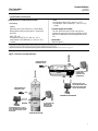
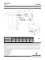
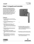
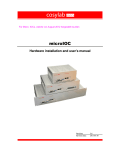
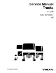
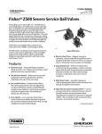
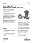
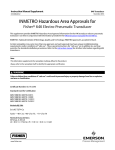
Product Bulletin L2e Controller 34.2:L2e June 2014 D103532X012 Fisherr L2e Electric Level Controller The rugged Fisher L2e electric on-off level controller uses a displacer type sensor to detect liquid level or the interface of two liquids of different specific gravities. This controller is ideal for controlling level in oil and gas separators, treaters, and scrubbers. The reliability of the L2e force balanced sensor design makes it well suited for applications in the oil and natural gas production, compression, and processing industries. Features n Repeatable Electric Level Control—In conjunction with the Fisher easy-Drive™ electric actuator, a fully electric level control loop is tunable for a wide variety of applications (see figure 1). X0660 n Effective Level Loop Tuning—Intuitive Zero and Span adjustments allow flexibility in setting loop performance over a level range of 5.0 to 559 mm (0.2 to 22 inches). n More Reliable Control—Premium quality hermetically-sealed switch with gold contacts and advanced knife-edge sensing provide highly dependable and accurate liquid level control. n On-Line Field Support—QR code on inside cover gives instrument technicians instant access to wiring, setup, calibration, tuning, and trouble-shooting. n Environmentally Responsible—Replacing a conventional pneumatic level loop with fully electric level control eliminates controller and dump valve venting and requires less maintenance. n Consumes No Electrical Power—Quality of design SCAN OR CLICK THE QR CODE FOR L2e AND easy-Drive ELECTRIC LEVEL LOOP FIELD SUPPORT n Field-Configurable Vertical or Horizontal Displacer—Displacer may be adjusted in the field for vertical or horizontal operation without additional parts. n Field Technician Friendly—The sensor can be easily disassembled to inspect or replace process seals. The controller, with no repairable or replaceable parts, is easily replaced in the field. n NACE Service Ready—Standard construction uses materials that comply with the requirements of NACE MR0175-2002. and components help ensure no leakage current. n CL1500 Pressure Rating—Sensor assembly is n Vibration Resistant Sensor Dynamics—Controller performance and reliability does not degrade in high vibration installations, such as on compressor scrubbers. www.Fisher.com designed and specified for ASME B16.34 CL1500 service when using a Polyvinylchloride (PVC) displacer. For PED (97/23/EC) maximum pressure is limited to 200 bar (2900 psig). Product Bulletin L2e Controller 34.2:L2e June 2014 D103532X012 Specifications Displacer Sizes J 48 X 305 mm, 541 cm3 (17/8 X 12 inches, 33 in3) J 76 X 152 mm, 688 cm3 (3 X 6 inches, 42 in3) Available Configurations Controller: On/Off electric control action with intuitive Zero and Span Adjustments in SPDT dry contact configuration Sensor: Displacertype liquid level sensor for mounting to side of vessel Maximum Displacer Rod Length(2), Horizontal or Vertical 1-7/8 x 12 Displacer with one 6-inch extension (optional use) 3 x 6 Displacer with one 3-inch extension (optional use) Input Type: Liquid level or liquidtoliquid interface Level Change Required for Full Change in State of Output: 5.0 to 559 mm (0.2 to 22 inches) Displacer Material and Maximum Sensor Working Pressure(3) PVC Displacer: Consistent with CL1500 pressure temperature ratings per ASME B16.34 up to maximum pressure of 258.5 bar (3750 psig) For PED (97/23/EC) maximum pressure limited to 200 bar (2900 psig) S31603 SST Displacer: CL600 pressure temperature ratings per ASME B16.34 up to maximum pressure of 99.3 bar (1440 psig) Note: For slipon flange connection, maximum sensor working pressure must be consistent with the flange ratings Vessel level differential gap (DG) is dependant on factors such as valve sizing, actuator speed, rate, liquid out flow, and vessel size. Contact your Emerson Process Management sales office for Fisher Electric Level Loop performance optimization Specific Gravity Limits Minimum SG: 0.15 Maximum SG PVC Displacer: 1.3 SST Displacer: 1.1 Electrical Rating (Output) Operative Ambient Temperature Limits(3) Controller: 40 to 75°C (40 to 167°F) J easy-Drive actuator application: 7 mA@5 VDC J Other applications: 1 amp resistive, 0.5 amp inductive/28 VDC Operative Process Temperature Limits(3) Sensor: J PVC Displacer: -18 to 71°C (0 to 160°F) J S31603 SST Displacer: 40 to 204°C (40 to 400°F) Note: Use with easy-Drive after first being used in other high power application is not recommended. Power Consumption Construction Materials Controller: Case and Cover: Marine grade aluminum Switch: Stainless steel Span Levers: Stainless steel Springs: Stainless steel Sensor: Sensor Body: LCC ORings: Fluorocarbon Pivot Assembly: Stainless steel Displacer: J Polyvinylchloride (PVC) or J S31603 SST Sensor Spring: Stainless steel Switch consumes no power to operate, so it has no current leakage or voltage drop Sensor to Vessel Connection J 2 NPT threaded or J NPS 2 CL150 through 1500 slipon flange connection(1) Controller Connection Electrical 1/2-14 NPT external conduit connection with 18 inches of 18 AWG lead wires, located at the bottom of the case -continued- 2 Product Bulletin L2e Controller 34.2:L2e June 2014 D103532X012 Specifications (continued) IECEx Flameproof Ex d IIC T6 (Ta=40°C to + 75°C) Dust Ex tb IIIC T85°C Db IP6X (Ta = 40° to +75°C) 1 A Max Hazardous Area Classifications Available Switch Only cCSAus Explosion-proof, Class I Division 1, Groups ABCD Dust Ignition-proof Class II Division 1, Groups EFG Dual Seal Canadian Registration (CRN) The L2e utilizes the same sensor unit pressure component as the L2 pneumatic controller version. Refer to L2 CRN which is deemed applicable to the L2e. ATEX II 2 GD Flameproof Ex d IIC T6 (Ta=40°C to + 75°C) Dust Ex tb IIIC T85°C Db IP6X (Ta = 40° to +75°C) 1 A Max Dimensions Refer to figure 2 NOTE: Specialized instrument terms are defined in ANSI/ISA Standard 51.1 Process Instrument Terminology. 1. Converting from a threaded NPT connection to a flange connection is to be done by the end-user. Refer to Converting a Threaded NPT Connection to a Flange Connection instruction Manual Supplement (D103277X012), available at www.Fisher.com or from your Emerson Process Management sales office. 2. Maximum span setting with 1-7/8 x 12 inch horizontal displacer plus 6 inch extension is not recommended due to potentially insufficient zero adjustment. 3. The pressure and temperature limits in this document and any applicable code limitations should not be exceeded. Figure 1. Electric Level Loop Solutions GAS PRODUCTION FLUID FROM WELL HEAD INLET GAS OIL WATER OIL L2e ELECTRIC LEVEL CONTROLLERS MAINTAIN LEVEL AT DESIRED DG GAS D3/D4 WITH easy-Drive ACTUATOR CONTROLS THE FLOW OF OIL AND WATER OUT OF THE SEPARATOR PRODUCTION FLUID FROM WELL HEAD INLET HORIZONTAL SEPARATOR OIL WATER FISHER D3/D4 WITH easy-Drive ACTUATOR CONTROLS THE FLOW OF OIL AND WATER OUT OF THE SEPARATOR L2e ELECTRIC LEVEL CONTROLLERS MAINTAIN LEVEL AT DESIRED DG VERTICAL SEPARATOR 3 Product Bulletin L2e Controller 34.2:L2e June 2014 D103532X012 Figure 2. Dimensions 191 (7.54) A B D C E LEVER ARM NPT OR SLIP-ON 1/2-14 NPT EXTERNAL CONDUIT CONNECTION F 88 (3.46) D 216 (8.51) 149 (5.87) E 142 (5.60) Sensor Configuration with Optional Extensions A B C D E F mm (Inch) 1-7/8 x 12 PVC Displacer with one 6-inch Extension 589 (23.19) 335 (13.19) 287 (11.31) 302 (11.88) 48 (1.88) 318 (12.50) 3 x 6 PVC Displacer with one 3-inch Extension 363.4 (14.31) 258.7 (10.19) 211 (8.31) 152.4 (6.00) 76.2 (3.00) 168.1 (6.62) mm (INCH) Neither Emerson, Emerson Process Management, nor any of their affiliated entities assumes responsibility for the selection, use or maintenance of any product. Responsibility for proper selection, use, and maintenance of any product remains solely with the purchaser and end user. Fisher and easy-Drive are marks owned by one of the companies in the Emerson Process Management business unit of Emerson Electric Co. Emerson Process Management, Emerson, and the Emerson logo are trademarks and service marks of Emerson Electric Co. All other marks are the property of their respective owners. The contents of this publication are presented for informational purposes only, and while every effort has been made to ensure their accuracy, they are not to be construed as warranties or guarantees, express or implied, regarding the products or services described herein or their use or applicability. All sales are governed by our terms and conditions, which are available upon request. We reserve the right to modify or improve the designs or specifications of such products at any time without notice. Emerson Process Management Marshalltown, Iowa 50158 USA Sorocaba, 18087 Brazil Chatham, Kent ME4 4QZ UK Dubai, United Arab Emirates Singapore 128461 Singapore www.Fisher.com E 4 2013, 2014 Fisher Controls International LLC. All rights reserved.