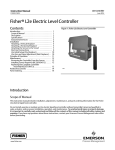
1
Instruction Manual
L2 Controller
D103032X012
September 2013
Fisherr L2 Liquid Level Controller
Contents
Introduction . . . . . . . . . . . . . . . . . . . . . . . . . . . . . . . . . 1
Scope of Manual . . . . . . . . . . . . . . . . . . . . . . . . . . . . . 1
Description . . . . . . . . . . . . . . . . . . . . . . . . . . . . . . . . . 3
Specifications . . . . . . . . . . . . . . . . . . . . . . . . . . . . . . . 3
Education Services . . . . . . . . . . . . . . . . . . . . . . . . . . . 3
Installation . . . . . . . . . . . . . . . . . . . . . . . . . . . . . . . . . . 4
Attaching Vertical Displacer . . . . . . . . . . . . . . . . . . . 4
Attaching Horizontal Displacer . . . . . . . . . . . . . . . . . 4
Attaching the Sensor to the Vessel . . . . . . . . . . . . . 5
Pressure Connections . . . . . . . . . . . . . . . . . . . . . . . . 5
Vent . . . . . . . . . . . . . . . . . . . . . . . . . . . . . . . . . . . . . . . 6
Changing Controller Action or Mode . . . . . . . . . . . . . 6
Throttling and On/Off Controllers . . . . . . . . . . . . . . 6
Snap‐Acting Controller . . . . . . . . . . . . . . . . . . . . . . . 6
Span Adjustment . . . . . . . . . . . . . . . . . . . . . . . . . . . . . 8
Preliminary Checks . . . . . . . . . . . . . . . . . . . . . . . . . . . 8
Direct‐Acting Throttling Controllers . . . . . . . . . . . . 9
Reverse‐Acting Throttling Controllers . . . . . . . . . . . 9
Direct‐Acting On/Off and
Snap‐Acting Controllers . . . . . . . . . . . . . . . . . . . . 9
Reverse‐Acting On/Off and
Snap‐Acting Controllers . . . . . . . . . . . . . . . . . . . . 9
Principle of Operation . . . . . . . . . . . . . . . . . . . . . . . . 10
Maintenance . . . . . . . . . . . . . . . . . . . . . . . . . . . . . . . . 11
Removing the Controller From the Sensor . . . . . . . . 11
Replacing the Sensor O‐Rings . . . . . . . . . . . . . . . . . 11
Disassembly . . . . . . . . . . . . . . . . . . . . . . . . . . . . 11
Assembly . . . . . . . . . . . . . . . . . . . . . . . . . . . . . . 13
Replacing the Controller Relay . . . . . . . . . . . . . . . . 13
Replacing the Controller Supply Filter . . . . . . . . . . 13
Figure 1. Fisher L2 Liquid Level Controller
W8418‐1
Related Documents . . . . . . . . . . . . . . . . . . . . . . . . . .
Parts Ordering . . . . . . . . . . . . . . . . . . . . . . . . . . . . . . .
Parts Kits . . . . . . . . . . . . . . . . . . . . . . . . . . . . . . . . . . .
Parts List . . . . . . . . . . . . . . . . . . . . . . . . . . . . . . . . . . .
Controller . . . . . . . . . . . . . . . . . . . . . . . . . . . . . . . . .
Sensor . . . . . . . . . . . . . . . . . . . . . . . . . . . . . . . . . . . .
14
14
14
14
14
16
Introduction
Scope of Manual
This instruction manual includes installation, adjustment, maintenance, and parts ordering information for the Fisher
L2 liquid level controller.
Do not install, operate or maintain an L2 Liquid Level Controller without being fully trained and qualified in valve,
actuator, and accessory installation, operation, and maintenance. To avoid personal injury or property damage, it is
important to carefully read, understand, and follow all contents of this manual, including all safety cautions and
warnings. If you have any questions about these instructions, contact your Emerson Process Management sales office
before proceeding.
www.Fisher.com
L2 Controller
Instruction Manual
September 2013
D103032X012
Table 1. Specifications
between 1.4 and 5.2 bar (20 and 50 psig) direct, and
1.4 bar and 2.4 bar (20 and 35 psig) reverse
Available Configurations
Controller: Snap‐acting or throttling
Sensor: Displacer‐type liquid level sensor for
mounting to side of tank. Displacer travel is
transmitted to controller by pivotal movement of
displacer rod
Do not use supply pressure below 1.4 bar (20 psig)
Supply Medium
Air or natural gas(4)
Input Signal
Steady‐State Air Consumption(5)
Type: Liquid level or liquid‐to‐liquid interface
Throttling Controller: ≤0.03 normal m3/hr (1.0 scfh)
at 1.4 bar (20 psig) supply pressure
Snap‐Acting Controller: ≤0.03 normal m3/hr (1.0
scfh) at 1.4 bar (20 psig) supply pressure or ≤0.04
normal m3/hr (1.5 scfh) at 2.4 bar (35 psig) supply
pressure in tripped condition; air consumption
increases during trip
Level Change Required for Full Change in Output
Signal in 1.0 Specific Gravity Liquid, with 1.4 Bar (20
Psig) Supply Pressure, Direct Action, and Standard 48
x 305 mm (1‐7/8 X 12‐Inch) Vertical Displacer with
Standard Lever Arm Length:
Maximum Proportional
Band Level Change, mm
(Inches)(1)
305 (12)
Sensor to Vessel Connection
Throttling
Minimum Proportional
Band Level Change, mm
(Inches)(1)
102 (4)
On/Off
127 (5)
305 (12)
Snap‐acting
13 (0.5)
20 (0.8)
slip‐on flange connection(6)
Control
Mode
J 2 NPT threaded or J NPS 2 CL150 through 1500
Controller Connections
Minimum Specific Gravity(2)
Supply: 1/4 NPT internal located on the bottom of the
case
Output: 1/4 NPT internal located on the top of the
case
Case Vent: 1/4 NPT internal with vent screen
assembly located on the back of the case
Throttling and On/Off Controllers: Minimum specific
gravity, or specific gravity differential for interface
applications, is 0.1 (see footnote 3)
Snap‐Acting Controllers: Minimum specific gravity, or
specific gravity differential for interface applications,
is 0.1
Standard Displacer Size
48 x 305 mm, 541 cm3 (1‐7/8 x 12 inches, 33 in3)
Output Signal
Pneumatic J on‐off or J proportional pressure
signal
Ranges:
Throttling: J 0.2 to 1.0 bar (3 to 15 psig) or J 0.4 to
2.0 bar (6 to 30 psig)
On/Off: 0 (off) or full supply pressure (on)
Action: Field‐reversible between direct (increasing
level increases output signal) and reverse (increasing
level decreases output signal)
Maximum Displacer Insertion Length(7)
Standard lever arm length plus one 6‐inch extension,
horizontal or vertical
Displacer Material and Maximum Sensor Working
Pressure(8)
PVC Displacer: Consistent with CL1500 pressure
temperature ratings per ASME B16.34 up to
maximum pressure of 258 bar (3750 psig)
For PED (97/23/EC) maximum pressure limited to 200
bar (2900 psig)
Supply Pressure Requirements
Throttling and On/Off Controller
Throttling: 1.4 bar for 0.2 to 1.0 bar output signal (20
psig for 3 to 15 psig output signal) and 2.4 bar for 0.4
to 2.0 bar output signal (35 psig for 6 to 30 psig
output signal)
On/Off: Any desired pressure between 1.4 and 3.4 bar
(20 and 50 psig).
Snap‐Acting Controller: Any desired pressure
S31603 SST Displacer: CL600 pressure temperature
ratings per ASME B16.34 up to maximum pressure of
99.3 bar (1440 psig)
Note: For slip‐on flange connection, maximum sensor
working pressure must be consistent with the flange
ratings
-Continued-
2
Instruction Manual
L2 Controller
D103032X012
September 2013
Table 1. Specifications (continued)
Displacer Material and Sensor Temperature
Limits(8)
PVC Displacer -29 to 79_C (-20 to 175_F)
S31603 SST Displacer: -40 to 204_C (-40 to 400_F)
Operative Ambient Temperature Limits(8)
Controller: -29 to 71_C (-20 to 160_F)
Standard Supply, and Output Pressure Gauge
Indications
Triple scale gauges in 0 to 60 psig/0 to 0.4 MPa/0 to
4.0 bar
Hazardous Area Classification
Complies with the requirements of ATEX Group II
Category 2 Gas and Dust
Declaration of SEP
Fisher Controls International LLC declares this
product to be in compliance with Article 3 paragraph
3 of the Pressure Equipment Directive (PED) 97 / 23 /
EC. It was designed and manufactured in accordance
with Sound Engineering Practice (SEP) and cannot
bear the CE marking related to PED compliance.
However, the product may bear the CE marking to
indicate compliance with other applicable European
Community Directives.
NOTE: Specialized instrument terms are defined in ISA Standard 51.1 - Process Instrument Terminology.
1. Any deviation from the standard construction described in the input signal specification above requires special displacer sizing considerations. Contact your Emerson Process Management sales
office for information.
2. Depends on float rod/displacer orientation and length. Contact your Emerson Process Management sales office for further information.
3. Minimum specific gravity differential with standard displacer is 0.4. Minimum specific gravity differential of 0.1 is possible with special displacer, consult your Emerson Process Management sales
office for displacer sizing information.
4. This product can be used with natural gas as the supply medium. Natural gas should contain no more than 20 ppm of H2S
5. Normal m3/hr—Normal cubic meters per hour (0_C and 1.01325 bar, absolute) Scfh—Standard cubic feet per hour (60_F and 14.7 psia).
6. Converting from a threaded NPT connection to a flange connection is to be done by the end-user. Refer to Converting a Threaded NPT Connection to a Flange Connection instruction Manual
Supplement (D103277X012), available at www.Fisher.com or from your Emerson Process Management sales office.
7. Standard lever arm length.
8. The pressure and temperature limits in this document and any applicable code limitations should not be exceeded.
Description
The rugged L2 liquid level controllers use a displacer type sensor (see figure 1) to detect liquid level or the interface of
two liquids of different specific gravities.
These controllers use a single four‐mode relay to provide the applicable control and action. The device delivers a
pneumatic output signal to a control/dump valve.
Unless otherwise noted, all NACE references are to NACE MR0175‐2002.
Specifications
Specifications for the controller and sensor are listed in table 1.
Educational Services
For information on available courses for L2 Liquid Level Controllers, as well as a variety of other products, contact:
Emerson Process Management
Educational Services, Registration
P.O. Box 190; 301 S. 1st Ave.
Marshalltown, IA 50158-2823
Phone: 800-338-8158 or
Phone: 641-754-3771
FAX: 641-754-3431
e‐mail: [email protected]
3
L2 Controller
Instruction Manual
September 2013
D103032X012
Installation
WARNING
Always wear protective clothing, gloves, and eyewear when performing any installation operations to avoid personal
injury.
To avoid personal injury or property damage caused by the sudden release of process fluid, be certain the service
conditions do not exceed the sensor pressure limits. Use pressure‐limiting or pressure‐relieving devices to prevent service
conditions from exceeding these limits.
Personal injury or property damage may result from fire or explosion if natural gas is used as the supply medium and
appropriate preventive measures are not taken. Preventive measures may include, but are not limited to, one or more of
the following: Remote venting of the unit, re‐evaluating the hazardous area classification, ensuring adequate ventilation,
and the removal of any ignition sources. For information on remote venting of this controller,
refer to page 6.
Check with your process or safety engineer for any additional measures that must be taken to protect against process
media.
If installing this into an existing application, also refer to the WARNING at the beginning of the Maintenance section of this
instruction manual.
CAUTION
If the L2 level controller is installed on a vessel that is to be shipped to a different location (e.g. skid mounted units), remove
the displacer and displacer rod extensions before shipment. Failure to do so could result in damage to the displacer rod due
to vibration and impact loading during shipment. After the vessel is installed at its final location, reassemble the displacer
and displacer rod extension.
1. Be sure there are no obstructions inside the tank that will interfere with displacer installation or operation.
2. Provide the appropriate connection in the tank wall to match the sensor connection. Locate the tank wall
connection such that the displacer will be at the desired control level.
Attaching a Vertical Displacer
Refer to figure 7 for part locations.
1. Thread jam nut (key 68) all the way onto the threaded portion of the universal joint assembly (key 69).
2. Thread the displacer (key 81) all the way onto the threaded portion of the universal joint assembly.
3. Tighten the jam nut (key 63) against the displacer (key 81).
Attaching a Horizontal Displacer
Refer to figure 7 for part locations.
1. Thread the displacer (key 81) all the way onto the displacer rod (key 64) or extension (key 82).
2. Tighten the jam nut (key 63) against the displacer (key 81).
4
Instruction Manual
L2 Controller
D103032X012
September 2013
Attaching the Sensor to the Vessel
Insert the displacer end of the controller‐sensor assembly into the tank connection, and screw the sensor threads into
the tank connection. Tighten sufficiently to seal the threads. If necessary, loosen or tighten slightly to obtain the
orientation shown in figure 2. Make sure that the controller case is level.
CAUTION
Do not pick up the controller/sensor by lifting the displacer rod (key 64). This action could place excessive stress on the
displacer rod and cause the unit to malfunction.
Figure 2. Sensor Orientation
CORRECT CONTROLLER MOUNTING
HOLE ORIENTATION WHEN MOUNTED ON VESSEL
A6639
Pressure Connections
WARNING
Personal injury or property damage may occur from an uncontrolled process if the supply medium is not clean, dry, oil‐free
air, or non‐corrosive gas. While use and regular maintenance of a filter that removes particles larger than 40 micrometers
in diameter will suffice in most applications, check with an Emerson Process Management field office and industry
instrument air quality standards for use with corrosive air or if you are unsure about the proper amount or method of air
filtration or filter maintenance.
1. Provide a source of clean, dry air that meets the requirements of ISA Standard 7.0.01 as the operating medium.
Refer to table 1 to determine supply pressure.
2. Connect the supply pressure to the 1/4 NPT internal connection on the bottom of the controller case.
3. Connect the output signal line to the equipment being operated and to the 1/4 NPT output connection on the top
of the controller case.
5
L2 Controller
Instruction Manual
September 2013
D103032X012
Vent
WARNING
If a flammable or hazardous gas is to be used as the supply pressure medium, personal injury or property damage could
result from fire or explosion of accumulated gas or from contact with hazardous gas. The controller/actuator assembly
does not form a gas‐tight seal, and when the assembly is enclosed, a remote vent line, adequate ventilation, and necessary
safety measures should be used. However, a remote vent pipe alone cannot be relied upon to remove all hazardous gas.
Vent line piping should comply with local and regional codes and should be as short as possible with adequate inside
diameter and few bends to reduce case pressure buildup.
The vent opening or the end of the remote vent pipe, if one is required, must be protected against the entrance of all
foreign matter that could plug the vent. Use 13 mm (1/2‐inch) diameter pipe for the remote vent pipe. Check the vent
periodically to be certain it is free of any obstructions.
Changing Controller Action or Mode
WARNING
To avoid personal injury caused by a sudden release of pressure, shut off the supply pressure and bleed pressure from the
supply lines before performing any procedure in this section.
Throttling and On/Off Controller
The action of a throttling and on/off controller may be changed between either direct or reverse, and the control
mode may be changed between either on/off or throttling.
Refer to figure 3. Loosen the four switch retention screws on the relay. Move the switches to the control action and
control mode required by the application. Tighten the four switch retention screws.
Snap‐Acting Controller
The action of a snap‐acting controller may be changed between either direct or reverse. The control mode is always
snap acting.
Refer to figure 4. Loosen the four switch retention screws on the relay. Move the switches to the control action
required by the application. Tighten the four switch retention screws.
6
Instruction Manual
L2 Controller
D103032X012
September 2013
Figure 3. Fisher L2 Throttling and On/Off Controller Switch Positions for Changing Action and Control Mode
SWITCH RETENTION
SCREWS 1
SWITCH RETENTION
SCREWS 1
DIRECT ACTION THROTTLING
CONTROL MODE
DIRECT ACTION ON/OFF
CONTROL MODE
REVERSE ACTION ON/OFF
CONTROL MODE
REVERSE ACTION THROTTLING
CONTROL MODE
NOTE:
1
ALL
FOUR SWITCH RETENTION SCREWS SHOWN ONLY ON THIS VIEW.
OTHER VIEWS SHOW ONLY TWO SWITCH RETENTION SCREWS IN ORDER TO
ILLUSTRATE THE SWITCH CONFIGURATION.
B2339
Figure 4. Fisher L2 Snap‐Acting Controller Switch Positions for Changing Action
SWITCH RETENTION
SCREWS 1
SWITCH RETENTION
SCREWS 1
B2340
DIRECT ACTION
NOTE:
1
ALL
FOUR SWITCH RETENTION SCREWS SHOWN ONLY ON THIS VIEW.
OTHER VIEWS SHOW ONLY TWO SWITCH RETENTION SCREWS IN ORDER TO
ILLUSTRATE THE SWITCH CONFIGURATION.
REVERSE ACTION
7
L2 Controller
Instruction Manual
September 2013
D103032X012
Span Adjustment
Except where indicated, key numbers referenced in the following procedures are shown in figure 8. The span levers
and other proportional band information are shown in figure 5.
Figure 5. Proportional Band Adjustments
SPAN LEVER GAP
MINIMUM SPAN (MOST SENSITIVE) POSITION
FOR THROTTLING AND ON/OFF CONTROLLER.
MAXIMUM SPAN (LEAST SENSITIVE) POSITION
FOR SNAP‐ACTING CONTROLLER
LEVER A
LEVER B
MAXIMUM SPAN (LEAST SENSITIVE) POSITION FOR
THROTTLING AND ON/OFF CONTROLLER. MINIMUM SPAN
(MOST SENSITIVE) POSITION FOR SNAP‐ACTING
CONTROLLER
LEVER A CONTACTING
THE DISPLACER ROD
GB0137-2
E0787
Preliminary Checks
1. Check the supply pressure gauge (key 10) to be certain that the supply pressure is at the desired value. Adjust the
supply pressure as required.
2. Adjust the displacer rod to the horizontal position with the spring adjustment (key 4).
3. Bounce the end of the displacer rod (key 64, figure 7) up and down to check that the sensor is operating freely.
4. Place the span adjuster (key 9) at the desired position (see figure 5).
8
Instruction Manual
L2 Controller
D103032X012
September 2013
5. Check figures 3 and 4 for correct control action and control mode.
6. Adjust the relay adjustment screw (key 49, throttling controller) or the valve assembly (key 51, snap‐acting
controller) so that the gap between the span levers (see figure 5) is equal when lever A is contacting the displacer
rod.
Direct‐Acting Throttling Controllers
1. Make certain the Preliminary Checks procedure at the start of this section has been completed.
2. Lower the liquid level so that it is below the bottom of the displacer or at the lowest desired operating point on the
displacer. For interface applications, completely cover the displacer with the fluid with the lower specific gravity.
The heavier fluid should be below the bottom of the displacer or at the lowest desired operating point on the
displacer.
3. Adjust the spring adjustment (key 4) until the output pressure is 1 to 2 psig for a 3 to 15 psig output range, or 2 to 4
psig for a 6 to 30 psig output range.
Reverse‐Acting Throttling Controllers
1. Make certain the Preliminary Checks procedure at the start of this section has been completed.
2. Lower the liquid level so that it is below the bottom of the displacer or at the lowest desired operating point on the
displacer. For interface applications, completely cover the displacer with the fluid with the lower specific gravity.
The heavier fluid should be below the bottom of the displacer or at the lowest desired operating point on the
displacer.
3. Adjust the spring adjustment (key 4) until the output is 16 to 17 psig for a 3 to 15 psig output range, or 31 to 34
psig for a 6 to 30 psig output range.
Direct‐Acting On/Off and Snap‐Acting Controllers
1. Make certain the Preliminary Checks procedure at the start of this section has been completed.
2. Lower the liquid level so that it is below the bottom of the displacer or at the lowest desired operating point on the
displacer. For interface applications, completely cover the displacer with the fluid with the lower specific gravity.
The heavier fluid should be below the bottom of the displacer or at the lowest desired operating point on the
displacer.
3. Adjust the spring adjustment (key 4) until the output pressure is at full supply pressure.
4. Readjust the spring adjustment (key 4) until the output pressure goes to zero psig.
Reverse‐Acting On/Off and Snap‐Acting Controllers
1. Make certain the Preliminary Checks procedure at the start of this section has been completed.
2. Lower the liquid level so that it is below the bottom of the displacer or at the lowest desired operating point on the
displacer. For interface applications, completely cover the displacer with the fluid with the lower specific gravity.
The heavier fluid should be below the bottom of the displacer or at the lowest desired operating point on the
displacer.
3. Adjust the spring adjustment (key 4) until the output pressure goes to zero psig.
4. Readjust the spring adjustment (key 4) until the output pressure goes to full supply pressure.
9
L2 Controller
Instruction Manual
September 2013
D103032X012
Principle of Operation
The operation of L2 controllers in combination with the sensor is based on Archimedes Principle, which states that a
body immersed in a liquid will be buoyed up by a force equal to the weight of the liquid displaced. The buoyant force
and resultant movement of the displacer in the liquid is transmitted to the controller which delivers a pneumatic signal
to a control valve.
Figure 6 shows a simple schematic of the controller and sensor. In its normal position, the counterclockwise moment
due to the weight of the displacer about pivot point O is balanced by the clockwise zero spring moment and the
counterclockwise relay zero force moment applied through lever A to the displacer rod. The weight of the displacer
decreases when the liquid level increases and the subsequent buoyant force increases causing a force imbalance
between the zero spring, relay, and displacer forces. This force imbalance is transmitted to the relay by levers A and B.
The relay compensates for the force imbalance by converting it to a pressure output to a control valve and bringing the
forces back into equilibrium.
Figure 6. Operational Schematic
LEVER B
DISPLACER ROD
PROPORTIONAL
BAND ADJUSTMENT
RELAY
PIVOT
POINT O
LEVER A
ZERO
SPRING
DISPLACER
A5592
For throttling control, the relay pressure output will be proportional to the buoyant force. For on/off control, the relay
pressure output will be either zero or equal to the supply pressure over the range of liquid level change. The liquid level
change required to fully operate the relay is adjusted by sliding the proportional band adjustment along lever A to vary
the lever ratio between levers A and B.
With reverse‐acting proportional control, the principle of operation remains the same as that for direct action;
however, the controller delivers an increasing pneumatic signal to the control valve when the liquid level falls.
10
Instruction Manual
L2 Controller
D103032X012
September 2013
Maintenance
Parts are subject to normal wear and must be inspected periodically and replaced as necessary. The frequency of parts
inspection and replacement depends upon the severity of service conditions. When inspection or repairs are required,
disassemble only those parts necessary to accomplish the task.
WARNING
Always wear protective clothing, gloves, and eyewear when performing any maintenance operations to avoid personal
injury.
To avoid personal injury or property damage caused by the release of pressure or process fluid, observe the following
before starting maintenance:
D Personal injury or property damage may result from fire or explosion if natural gas is used as the supply medium and
appropriate preventive measures are not taken. Preventive measures may include, but are not limited to, one or more
of the following: Remote venting of the unit, re‐evaluating the hazardous area classification, ensuring adequate
ventilation, and the removal of any ignition sources. For information on remote venting of this controller, refer to
page 6.
D Provide some temporary means of control for the process before taking the controller out of service.
D Provide a means of containing the process fluid before removing any measurement devices from the process.
D Vent any trapped process pressure.
D Check with your process or safety engineer for any additional measures that must be taken to protect against process
media.
Removing the Controller From the Sensor
1. Disconnect the supply and output pressure lines.
2. Slide the hook end of the zero spring (key 5, figure 8) over and off the controller end of the displacer rod
(key 64, figure 7).
3. Remove the four controller mounting screws (key 11, figure 8), and pull the controller straight away from the
sensor.
Replacing the Sensor O‐Rings
Refer to figure 7 for key number locations unless otherwise indicated.
Disassembly
1. Remove the controller from the sensor by following the procedure outlined in the previous section.
2. Remove the sensor from the tank.
3. Unscrew the hex nut (key 67) and remove the spacer (key 66) and spring (key 68). After removing the spring,
replace the spacer (key 66) and hex nut (key 67) on the displacer rod.
From the displacer end, pull the displacer rod away from the sensor connection (key 65) to pull the pivot base
(key 73) loose from the sensor connection. Remove the hex nut (key 67) to permit removing the displacer rod,
pivot base, pivot body, and spacer from the sensor connection.
11
L2 Controller
Instruction Manual
September 2013
D103032X012
4. Slide the pivot base (key 73), retaining ring (key 76), anti‐extrusion ring (key 75), and O‐ring (key 74) off the
displacer rod. Remove the O‐ring (key 77) and backup ring (key 78) from the pivot base.
Figure 7. Sensor
C
A
A
C
VIEW C ‐ C
B
SECTION A ‐ A
VIEW B
APPLY LUB/SEALANT
GB0139-C, sht 1
12
Instruction Manual
L2 Controller
D103032X012
September 2013
Assembly
WARNING
Improper assembly of the O‐rings, anti‐extrusion ring, and backup ring could result in O‐ring extrusion and permit leakage
of process fluids. To avoid personal injury or property damage from leaking process fluid, be sure the O‐rings,
anti‐extrusion ring and backup ring are assembled in the order shown in figure 7.
1. Place the pivot body (key 72) on the displacer rod (key 64) so that it is positioned as shown in figure 7.
2. Slide the O‐ring (key 74), anti‐extrusion ring (key 75) and retaining ring (key 76) onto the displacer rod assembly
(key 64). Be sure the O‐ring, anti‐extrusion ring, and retaining ring are in the order shown in figure 7. Slide the pivot
base onto the displacer rod so that the points of the pivot body (key 72) will engage the slots in the pivot base
(key 73).
3. Install the O‐ring (key 77) and backup ring (key 78) into the groove on the pivot base (key 73). Be sure the backup
ring is on the downstream pressure side of the O‐ring as shown in figure 7.
4. Insert the displacer rod (key 64) into the vessel side of the sensor connection (key 65).
5. The pivot base must seat in the slots cast in the sensor connection. These slots will be horizontal when the sensor
connection (key 65) is oriented as shown in figure 2.
6. To reduce the possibility of nicking the O‐ring (key 77) on the pivot base, keep the displacer rod centered in the
sensor connection as much as possible while pushing the pivot base into the sensor connection. Be sure the pivot
base seats in the slots cast in the sensor connection.
7. Slide the spring (key 68) and spacer (key 66) onto the displacer rod and secure with the hex nut (key 67). Fully
tighten the hex nut (key 67).
8. View the sensor connection from the vessel side. Ensure that the pivot body arms remain aligned with the pivot
base arms (the two pivot body points are seated in the pivot base slots).
9. Install the sensor on the tank.
Replacing the Controller Relay
Refer to figure 8 for key number locations unless otherwise indicated.
1. Disconnect the supply and output pressure lines.
2. Remove the two relay mounting screws (key 33), and pull the relay away from the controller base (key 1).
3. Install the new relay using two relay mounting screws (key 33). Make certain that the relay mounting O‐rings (keys
43 and 44, not shown) are completely in their mounting bosses before installing the relay. Make certain span lever B
(see figure 5) is in line with and pushing in on the end of either the relay adjustment screw (key 49, throttling
controller) or the pilot valve plug of the valve assembly (key 51, snap‐acting controller).
Replacing the Controller Supply Filter
Refer to figure 8 for key number locations unless otherwise indicated.
1. Disconnect the supply and output pressure lines.
2. Loosen the filter cap screws (key 17), and rotate the filter cap (key 14) to the side to uncover the supply filter
(key 15).
3. Remove the old filter (key 15), and remove any debris from the filter boss.
4. Install a new supply filter. Reinstall the filter cap (key 14), and tighten the filter cap screws (key 17).
13
L2 Controller
Instruction Manual
September 2013
D103032X012
Related Documents
D Converting a Threaded NPT Connection to a Flange Connection—Supplement to Fisher L2 and L2sj Liquid Level
Controller Instruction Manuals (D103277X012)
D Dimensions for NPS 2 CL150 through 1500 Slip On Flange Connections—Supplement to Fisher L2 and L2sj Liquid
Level Controller Instruction Manuals (D103405X012)
D Fisher L2sj Low Emission Liquid Level Controller Instruction Manual (D103216X012)
All documents are available from your Emerson Process Management sales office. Also visit our website at
www.Fisher.com.
Parts Ordering
When corresponding with your Emerson Process Management sales office about this equipment, always mention the
serial number of the controller.
The serial number can be found on the nameplate (key 55, figure 8). When ordering replacement parts, also specify
the complete 11‐character part number of each part required as found in the following parts list.
WARNING
Use only genuine Fisher replacement parts. Components that are not supplied by Emerson Process Management should
not, under any circumstances, be used in any Fisher instrument. Use of components not supplied by Emerson Process
Management may void your warranty, might adversely affect the performance of the valve, and could cause personal
injury or property damage.
Parts Kits
Description
Part Number
Note
For part numbers not shown, contact your Emerson Process
Management sales office.
Controller
Repair kit includes O‐rings (keys 13 and 16) and
gaskets (keys 18, 21, and 23)
RL2CNTRX012
Relay
Repair kits includes relay assembly,
relay mounting screws (key 33), and
O‐rings (keys 43 and 44)
Throttling and On/Off Controller
Snap‐Acting Controller
GB0138X0012
GB0138X0022
Sensor
Repair kit includes keys 74, 75, 77, and 78
(fluorocarbon O‐rings, anti‐extrusion ring,
and fluorocarbon backup ring)
14
Parts List
Controller
RL2SENSX012
Key
Description
1
2
3
4
5
Controller Base, marine grade aluminum
Zero Spring Seat, 316 SST
Zero Adjustment Bolt, stainless steel
Spring Adjustment, 316 SST
Zero Spring, 17‐7PH SST
Instruction Manual
L2 Controller
D103032X012
September 2013
Figure 8. Fisher L2 Liquid Level Controllers
THROTTLING AND ON/OFF
CONTROLLER RELAY ASSY
A
A
THROTTLING AND ON/OFF CONTROLLER
SNAP‐ACTING CONTROLLER
RELAY ASSEMBLY
VIEW A‐A
SNAP‐ACTING CONTROLLER
APPLY LUB/SEALANT
GB0137-D
15
L2 Controller
Instruction Manual
September 2013
D103032X012
Key
Description
Part Number
6
7
Span Lever Assembly, stainless steel
Shoulder Screw, stainless steel (2 req'd)
8
9
10
11
Flanged Bearing, nylon (4 req'd)
Span Adjustor, stainless steel
Pressure Gauge (2 req'd)
Mounting Screw, stainless steel (4 req'd)
12
13*
Cover Screw, stainless steel
O‐Ring(1), nitrile
14
15
16*
17
18*
19
Filter Cap, reinforced PMMA (polymethylmethacrylate)
Filter
11B2307X012
O‐Ring(1), nitrile
Machine Screw, stainless steel (2 req'd)
Sensor Gasket(1), composition
Cover, marine grade aluminum
20
21*
22
Cover Lens, PMMA (polymethylmethacrylate) (2 req'd)
Gasket(1), chloroprene (2 req'd)
Retaining Ring, steel (2 req'd)
23*
Cover Gasket(1), nitrile
33
Relay Mounting Screw(2), stainless steel (2 req'd)
43*
Relay Mounting O‐Ring(2), nitrile (not shown)
44*
49
Relay Mounting O‐Ring(2), nitrile (not shown)
Relay Adjustment Screw
51
52
53
54
55
56
Valve Assembly
Valve Assembly O‐Ring
Label, setup and calibration
Self‐Tapping Screw, stainless steel (2 req'd)
Nameplate
Screen, stainless steel
Key
Description
57
60
Hex Nut, stainless steel
Anti‐seize sealant
(not furnished with controller)
Lubricant, silicone sealant
(not furnished with controller)
61
62
84
85
Part Number
Thread locking adhesive, medium strength
(not furnished with controller)
Adhesive, industrial grade cyanoacrylate
Nameplate, ATEX
Sensor
81
63
64
65
66
67
68
69
70
71
72
73
74*
75*
76
77*
78*
79
80
82
Displacer, 1‐7/8x12‐inches
PVC
S31603 SST
Hex Nut, 316 SST
Displacer Rod, 17‐4 SST (17‐4PH SST)
Sensor Connection
Spacer, 304 SST
Hex Nut, 316 SST
Conical Spring, 316 SST
Universal Joint, 316 SST (vertical displacer only)
Nameplate
Drive Screw, stainless steel
Pivot Body, CB7CU‐1 (17‐4PH SST)
Pivot Base, CF8M (316 SST)
O‐Ring(3), fluorocarbon
Anti‐Extrusion Ring(3), PTFE
Retaining Ring, 304 SST
O‐Ring(3), fluorocarbon
Backup Ring(3), fluorocarbon
Lithium grease
(not furnished with sensor)
Instruction Tag
Extension, S31600
12B2936X032
12B2956X032
12B2953X022
*Recommended spare parts
1. Included in Controller Repair Kit
2. Included in Relay Repair Kit
3. Included in Sensor Repair Kit
Neither Emerson, Emerson Process Management, nor any of their affiliated entities assumes responsibility for the selection, use or maintenance
of any product. Responsibility for proper selection, use, and maintenance of any product remains solely with the purchaser and end user.
Fisher is a mark owned by one of the companies in the Emerson Process Management business unit of Emerson Electric Co. Emerson Process Management,
Emerson, and the Emerson logo are trademarks and service marks of Emerson Electric Co. All other marks are the property of their respective owners.
The contents of this publication are presented for informational purposes only, and while every effort has been made to ensure their accuracy, they are not
to be construed as warranties or guarantees, express or implied, regarding the products or services described herein or their use or applicability. All sales are
governed by our terms and conditions, which are available upon request. We reserve the right to modify or improve the designs or specifications of such
products at any time without notice.
Emerson Process Management
Marshalltown, Iowa 50158 USA
Sorocaba, 18087 Brazil
Chatham, Kent ME4 4QZ UK
Dubai, United Arab Emirates
Singapore 128461 Singapore
www.Fisher.com
16
E 2001, 2013 Fisher Controls International LLC. All rights reserved.