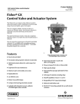
1
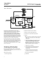
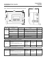
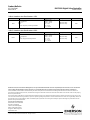
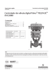
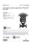
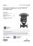
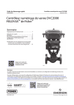
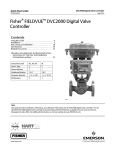
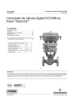
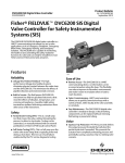
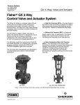
DVC2000 Digital Valve Controller
D103167X012
Product Bulletin
62.1:DVC2000
March 2014
Fisherr FIELDVUEt DVC2000 Digital Valve
Controller
The FIELDVUE DVC2000 digital valve controller is
simple to use, compact, and designed for easy
mounting. It converts a 4-20 mA input signal into a
pneumatic output signal, which feeds the control valve
actuator. Instrument setup is performed with a push
button and liquid crystal display (LCD) interface. This
interface is protected from the environment within a
sealed enclosure. The interface supports multiple
languages, available in two language pack options.
The DVC2000 uses a two-stage positioner design. The
pre-amplifier stage provides high static gain for
responsiveness to small changes in the input signal.
The power amplifier stage delivers the right volume of
air to the actuator, combining superior dynamic
W8755
www.Fisher.com
performance with minimal steady-state air
consumption.
The high performance, linkage-less feedback system
eliminates physical contact between the valve stem
and the positioner. There is no wear of parts so cycle
life is maximized. Additionally, the elimination of
levers and linkages reduces the number of mounting
parts and the mounting complexity. Positioner
replacement and maintenance is simplified because
the feedback parts stay connected to the actuator
stem.
Designed to meet intrinsically safe and non-incendive
requirements, this instrument delivers scalable
functionality and high performance in a small package.
Product Bulletin
DVC2000 Digital Valve Controller
62.1:DVC2000
March 2014
D103167X012
Specifications
Air Consumption(2)
Available Mountings
Supply pressure
At 1.5 bar (22 psig) (3): 0.06 normal m3/h (2.3 scfh)
At 4 bar (58 psig) (4): 0.12 normal m3/h (4.4 scfh)
J Integral mounting to the Fisher GX Control Valve
and Actuator System
J Sliding-stem applications
J Quarter-turn rotary applications
Air Capacity(2)
DVC2000 digital valve controllers can also be
mounted on other actuators that comply with
IEC 60534-6-1, IEC 60534-6-2, VDI/VDE 3845 and
NAMUR mounting standards.
Supply pressure
At 1.5 bar (22 psig) (3): 4.48 normal m3/h
(167 scfh)
At 4 bar (58 psig) (4): 9.06 normal m3/h (338 scfh)
Input Signal
Independent Linearity
Analog Input Signal: 4-20 mA DC, nominal; can be
configured for split range
Minimum Voltage: Voltage available at instrument
terminals must be 8.5 volts for analog control, 9.0
volts for HARTr communication
Maximum Voltage: 30 VDC
Minimum Control Current: 4.0 mA (below 3.5 mA
may cause microprocessor restart)
Overcurrent Protection: Input circuitry limits current
to prevent internal damage
Reverse Polarity Protection: No damage occurs from
reversal of loop current
±0.5% of output span
Electromagnetic Compatibility
Meets EN 61326-1 (First Edition)
Immunity—Industrial locations per Table 2 of
the EN 61326-1 standard. Performance is
shown in table 1 below
Emissions—Class A
ISM equipment rating: Group 1, Class A
Tested to NAMUR NE21 requirements
Vibration Testing Method
Output Signal
Tested per ANSI/ISA-75.13.01 Section 5.3.5. A
resonant frequency search is performed on all three
axes. The instrument is subjected to the ISA specified
1/2 hour endurance test at each major resonance,
plus an additional two million cycles.
Pneumatic signal as required by the actuator, up to
full supply pressure
Minimum Span: 0.5 bar (7 psig)
Maximum Span: 7 bar (101 psig)
Action: Single Acting, direct
Input Impedance
Supply Pressure(1)
The input impedance of the DVC2000 active
electronic circuit is not purely resistive. For
comparison to resistive load specifications, an
equivalent impedance of 450 ohms may be used. This
value corresponds to 9 V @ 20 mA.
Recommended: 0.5 bar (7 psig) greater than the
maximum actuator requirements
Maximum: 7 bar (101 psig)
Supply pressure must be clean, dry air or
noncorrosive, nonflammable gas that meets the
requirements of ISA Standard 7.0.01. A maximum 40
micrometer particle size in the air system is
acceptable. Further filtration down to 5 micrometer
particle size is recommended. Lubricant content is
not to exceed 1 ppm weight (w/w) or volume (v/v)
basis. Condensation in the air supply should be
minimized.
Electrical Classification
Hazardous Area:
CSA—Intrinsically Safe and Non-incendive
FM—Intrinsically Safe and Non-incendive
ATEX—Intrinsically Safe
IECEx—Intrinsically Safe
Refer to tables 2, 3, 4, and 5 for additional
information
Temperature Limits(1)
Electrical Housing:
CSA—IP66, Type 4X
FM, ATEX, IECEx—IP66
-40 to 85_C (-40 to 185_F). LCD may not be readable
below -20_C (-4_F).
-continued-
2
Product Bulletin
DVC2000 Digital Valve Controller
62.1:DVC2000
March 2014
D103167X012
Specifications (continued)
Other Classifications/Certifications
GOST‐R—Russian GOST‐R
INMETRO—National Institute of Metrology,
Quality and Technology (Brazil)
KGS— Korea Gas Safety Corporation (South Korea)
NEPSI—National Supervision and Inspection Centre
for Explosion Protection and Safety of
Instrumentation (China)
PESO CCOE—Petroleum and Explosives Safety
Organisation - Chief Controller of Explosives (India)
RTN—Russian Rostekhnadzor
Contact your Emerson Process Management sales
office for classification/certification specific
information
Connections
Standard
Supply and Output Pressure: G1/4 internal
Electrical: M20 internal
Optional
Supply and Output Pressure: 1/4 NPT internal
Electrical: 1/2 NPT internal
Materials of Construction
Housing and Cover: A03600 low copper aluminum
alloy
Elastomers: nitrile, fluorosilicone
Stem Travel
Minimum: 6.35 mm (0.25 inch)
Maximum: 606 mm (23-7/8 inches)
Shaft Rotation
Minimum: 45_
Maximum: 90_
Mounting
Designed for direct actuator mounting. For
weatherproof housing capability, the vent must be
positioned at the lowest point of the instrument.
Weight
1.5 kg (3.3 lbs)
Dimensions
Refer to figure 3
Options
J Airset: Fisher 67CFR with filter
Language Packs: J Standard: English, German,
French, Italian, Spanish, Japanese, Chinese,
Portuguese, Russian, Polish, and Czech
J Optional: English, German, French, Italian, Spanish,
Japanese, Chinese, and Arabic
J Pipe-away vent
J Limit Switches: Two isolated switches, configurable
throughout calibrated travel range
Supply Voltage: 5-30 VDC
OFF State: 0.5 to 1.0 mA
ON State: 3.5 to 4.5 mA (above 5 volts)
Reference Accuracy: 2% of travel span(5)
J Transmitter: 4-20 mA output, isolated
Supply Voltage: 8-30 VDC
Fault Indication: offrange high or low
Reference Accuracy: 1% of travel span(5)
1. The pressure/temperature limits in this document and any applicable standard or code limitation should not be exceeded. Note: Temperature limits vary based on hazardous area approval.
2. Normal m3/hour - Normal cubic meters per hour at 0_C and 1.01325 bar, absolute. Scfh - Standard cubic feet per hour at 60_F and 14.7 psia.
3. Low pressure relay: 0 to 3.4 bar (0 to 50 psig).
4. High pressure relay: 3.5 to 7.0 bar (51 to 102 psig).
5. Typical values when calibrated at temperature.
Features
n Simplicity—The DVC2000 is easy to use. If you are
mounting the instrument for the first time, the
linkage-less feedback system is easy to install. Once
a magnet array is assembled to the valve stem,
positioner replacement is simple since there are no
physically connected parts.
At its very basic functionality, the DVC2000 digital
valve controller has a local user interface that will
allow you to configure, calibrate, and tune the
instrument. If the I/O Options Package is installed,
you can calibrate the 4-20 mA transmitter and
configure the limit switch action. Running the Quick
Setup routine calibrates and tunes the instrument
specifically for that actuator.
The full text display in the local interface is easy to
navigate, in part due to the selection of languages.
Each unit can be configured to display English,
German, French, Italian, Spanish, Japanese or
Chinese. The standard language pack also includes
Portuguese, Russian, Polish, and Czech. An optional
language pack replaces these four languages with
Arabic.
3
Product Bulletin
62.1:DVC2000
March 2014
n Reliability—The DVC2000 is based on the
field-proven FIELDVUE technology. Years of control
experience has brought this product line to a high
level of reliability and dependability.
n Performance—The two-stage positioner design
provides a mechanical platform that enables
responsiveness to small input changes and tighter
process control. The digital tuning algorithm allows
optimal response to get the valve to its desired
position quickly.
n Diagnostics—Local User Interface: DVC2000
instruments come standard with a liquid crystal
display. Predefined instrument and valve
diagnostics are built into the firmware to alert you if
there are any problems with the mounting,
electronics, hardware, or valve performance.
Handheld Field Communicator: DVC2000
instruments are packed with user-configurable
alerts and alarms. These flags provide notification of
current status and potential valve and instrument
problems through alerts such as travel deviation,
travel limit, cycle count, and travel accumulation.
ValveLinkt software: Tests can be performed to
identify problems with the entire control valve
assembly using ValveLink software. Using valve
stem travel feedback, actuator pressure sensor, and
other sensors on the instrument, the health of the
control valve can be evaluated while the valve is still
in service and fully operational. This helps to
pinpoint problems without disrupting the process before the equipment fails.
DVC2000 Digital Valve Controller
D103167X012
Integration
Traditional 4-20 mA Systems
Because the DVC2000 instrument operates with a
4-20 mA control signal, it directly replaces older
analog instruments. Microprocessor based electronics
provide improved control performance along with
repeatable and reliable configuration and calibration.
Modbus with ValveLink Software
and HART Multiplexers
HART communication allows you to extract more
value from the DVC2000 instrument beyond its
inherent improved performance. When integrated into
a multiplexer network and using ValveLink software,
the device and valve information is real-time. From the
safety of a control room, multiple instruments can be
monitored for alerts and alarms.
Additionally, tasks such as configuration, calibration,
and diagnostic testing do not require special trips to
the field. ValveLink software can communicate via
Modbus to the distributed control system (DCS) to
provide critical information such as valve travel alerts
and alarms.
n I/O Options Package— The DVC2000 is available
with an I/O Options Package which includes two (2)
integral limit switches and a stem position
transmitter. The limit switches are configurable for
open and closed valve indication at any point
throughout the calibrated travel range. The position
transmitter provides a 4-20 mA signal for valve
position feedback verification. As an integral
component to the instrument, this option module
avoids the need for difficult-to-mount external
switches and transmitters.
4
Integrated Control System
A control system with HART communication
capabilities has the ability to directly gather
information from DVC2000 digital valve controllers.
Information such as valve travel, alerts and alarms can
be seamlessly accessed to provide a view into the field
device from the safety of the control room.
Product Bulletin
DVC2000 Digital Valve Controller
62.1:DVC2000
March 2014
D103167X012
Figure 1. FIELDVUE DVC2000 Digital Valve Controller Assembly (Exploded View)
HOUSING
MOUNTING
FRAME
SINGLE ACTING
RELAY
PRIMARY SHIELD
(FOR ELECTROMAGNETIC
INTERFERENCE PROTECTION)
TERMINAL /
SENSOR BOARD
VENT
INTERCONNECT
BOARD
I/P
CONVERTER
MAIN BOARD WITH LCD
AND PUSHBUTTONS
ENVIRONMENTAL
COVER WITH LENS
W8946
Principle of Operation
The DVC2000 (figures 1 and 2) receives a 4-20 mA set
point and position the valve by increasing or
decreasing the air output to an actuator.
n The input signal provides electrical power and the
set point simultaneously. The 4-20 mA signal is
routed into the terminals through a twisted pair of
wires.
n The unit's mainboard contains a microprocessor
that continuously runs a digital control algorithm.
This algorithm produces a “drive signal” to the I/P
converter.
relay output pressure to the actuator causes the
valve to move.
There are two relay options. The low pressure relay
operates with actuators that require less than
3.5 bar (50 psi) of supply air. The high pressure relay
operates with actuators that require 3.5 to 7.0 bar
(50 to 100 psi) of supply air.
n Valve position is sensed through the linkage-less
feedback system. The travel sensor is electrically
connected to the printed wiring board to provide a
travel feedback signal used in the control algorithm.
The valve continues to move until the correct
position is attained.
n The I/P converter assembly (or pre-amplifier) is
connected to supply pressure and converts the
electronic “drive signal” into a pneumatic “pressure
signal.” This pressure signal is the input to the
pneumatic relay assembly.
n The relay (or power amplifier) is also connected to
supply pressure and amplifies the small pressure
signal from the I/P converter into a larger pressure
output signal used by the actuator. The change in
Installation
The DVC2000 is designed for mounting on any
single acting pneumatic actuator up to 606 mm
(23-7/8 inches) of travel. The envelope and travel
feedback system conforms to VDI/VDE 3845, IEC
60534-6-1, and IEC 60534-6-2 standards.
5
Product Bulletin
DVC2000 Digital Valve Controller
62.1:DVC2000
March 2014
D103167X012
Figure 2. Block Diagram
NON-CONTACT
POSITION FEEDBACK
W8611
OUTPUT
INPUT SIGNAL
(4-20 mA, 9 VOLTS)
TERMINATIONS
AND
POSITION
SENSOR
BOARD
MAIN BOARD
ASSEMBLY
ACTUATOR
PRESSURE
SENSOR
Y
SINGLE ACTING
RELAY
(POWER
AMPLIFIER)
MINOR LOOP
FEEDBACK
TRAVEL = 66.8%
14.6 MA 0.29 BAR
I/P
PRESSURE
SIGNAL
I/P
CONVERTER
DRIVE
(PRESIGNAL AMPLIFIER
Furthermore, the DVC2000 instrument can be
integrally mounted to the GX actuator, avoiding the
need for complicated mounting brackets. The
positioner mounts directly to an interface pad on the
actuator yoke leg with a secure 3-point mounting.
Internal passages inside the actuator yoke legs route
the pneumatic output of the digital valve controller to
the actuator casing, eliminating the need for external
tubing (only for the air-to-open configuration).
Electrical connections are made on the termination
strip, which uses cage clamp style wiring connectors.
The electrical wiring entry point is available with either
M20 or 1/2 NPT internal connections. Pressure
connections are available with either G1/4 or 1/4 NPT
internal connections.
AIR SUPPLY
2. Maximum actuator travel or rotation
3. Minimum actuator operating pressure
4. Hazardous area certification requirements
5. Options
a.
J G1/4 pneumatic and M20 conduit connections
or J 1/4 NPT pneumatic and 1/2 NPT conduit
connections
b. Language pack: J Standard—English, German,
French, Italian, Spanish, Japanese, Chinese,
Portuguese, Russian, Polish, and Czech or
J Optional—English, German, French, Italian,
Spanish, Japanese, Chinese, and Arabic
c. Supply pressure regulator
Ordering Information
Refer to the Specifications section. Carefully review
each specification and indicate your choice whenever a
selection is to be made.
d. Valve diagnostic level (online performance
testing, offline advanced testing, basic
alerts/alarms)
e. I/O Options Package (includes position
transmitter and two (2) limit switches)
When ordering, specify:
f. Pipe-away vent connector
1. Actuator type and size
g. HART filter
6
Product Bulletin
DVC2000 Digital Valve Controller
62.1:DVC2000
March 2014
D103167X012
90
(3.55)
Figure 3. Dimensions for FIELDVUE DVC2000 Digital Valve Controller
165.6
(6.52)
106
(4.17)
mm
(INCH)
E0916-1
Table 1. EMC Summary Results—Immunity
Port
Enclosure
Phenomenon
Basic Standard
Test Level
6 kV contact
8 kV air
80 to 1000 MHz @ 10V/m with 1 kHz AM at 80%
1400 to 2000 MHz @ 3V/m with 1 kHz AM at 80%
2000 to 2700 MHz @ 1V/m with 1 kHz AM at 80%
Performance
Criteria(1)
Electrostatic discharge (ESD)
IEC 61000-4-2
Radiated EM field
IEC 61000-4-3
Rated power frequency magnetic
field
IEC 61000-4-8
30 A/m at 50 Hz, 60 sec
A
Burst (fast transients)
IEC 61000-4-4
$1 kV
A
IEC 61000-4-5
$1 kV (line to ground only, each)
B
IEC 61000-4-6
150 kHz to 80 MHz at 10 Vrms
A
I/O signal/control Surge
Conducted RF
B
A
Performance criteria is + / - 1% effect.
1. A = No degradation during testing. B = Temporary degradation during testing, but is self-recovering.
Table 2. Hazardous Area Classifications—CSA (Canada)
Certification Body
CSA
Certification Obtained
Intrinsically Safe
Ex ia IIC T4/T5 per drawing GE12444
Class I Division 1 GP A,B,C,D per drawing GE12444
Non-incendive
Class I Division 2 GP A,B,C,D T5
Entity Ratings
(Main Circuit)
Vmax = 30 VDC
Imax = 130 mA
Pi = 1.0 W
Ci = 10.5 nF
Li = 0.55 mH
---
Temperature Code
Enclosure Rating
T4(Tamb ≤ 80C)
T5(Tamb ≤ 40C)
IP66
T5(Tamb ≤ 80C)
IP66
Table 3. Hazardous Area Classifications—FM (United States)
Certification Body
FM
Certification Obtained
IS Intrinsically Safe
Class I Division 1 GP A,B,C,D T4/T5 per drawing GE10683
Class I Zone 0 AEx ia IIC per drawing GE10683
NI Non-incendive
Class I Division 2 GP A,B,C,D T5
Entity Ratings
(Main Circuit)
Vmax = 30 VDC
Imax = 130 mA
Pi = 1.0 W
Ci = 10.5 nF
Li = 0.55 mH
---
Temperature Code
Enclosure Rating
T4(Tamb ≤ 80C)
T5(Tamb ≤ 40C)
IP66
T5(Tamb ≤ 80C)
IP66
7
Product Bulletin
DVC2000 Digital Valve Controller
62.1:DVC2000
March 2014
D103167X012
Table 4. Hazardous Area Classifications—ATEX
Certification
ATEX
Certification Obtained
Intrinsically Safe
II 1 G
Gas
Ex ia IIC T4/T5 Ga per drawing GE14685
Entity Ratings
(Main Circuit)
Vmax = 30 VDC
Imax = 130 mA
Pi = 1.0 W
Ci = 10.5 nF
Li = 0.55 mH
Temperature Code
T4(Tamb ≤ 80C)
T5(Tamb ≤ 40C)
Enclosure Rating
IP66
Table 5. Hazardous Area Classifications—IECEx
Certification
IECEx
Certification Obtained
Intrinsically Safe
Gas
Ex ia IIC T4/T5 per drawing GE14581
Entity Ratings
(Main Circuit)
Vmax = 30 VDC
Imax = 130 mA
Pi = 1.0 W
Ci = 10.5 nF
Li = 0.55 mH
Temperature Code
T4(Tamb ≤ 80C)
T5(Tamb ≤ 40C)
Enclosure Rating
IP66
Neither Emerson, Emerson Process Management, nor any of their affiliated entities assumes responsibility for the selection, use or maintenance
of any product. Responsibility for proper selection, use, and maintenance of any product remains solely with the purchaser and end user.
Fisher, FIELDVUE, and ValveLink are marks owned by one of the companies in the Emerson Process Management business unit of Emerson Electric Co.
Emerson Process Management, Emerson, and the Emerson logo are trademarks and service marks of Emerson Electric Co. All other marks are the property
of their respective owners.
The contents of this publication are presented for informational purposes only, and while every effort has been made to ensure their accuracy, they are not
to be construed as warranties or guarantees, express or implied, regarding the products or services described herein or their use or applicability. All sales are
governed by our terms and conditions, which are available upon request. We reserve the right to modify or improve the designs or specifications of such
products at any time without notice.
Emerson Process Management
Marshalltown, Iowa 50158 USA
Sorocaba, 18087 Brazil
Chatham, Kent ME4 4QZ UK
Dubai, United Arab Emirates
Singapore 128461 Singapore
www.Fisher.com
E
8 2004, 2014 Fisher Controls International LLC. All rights reserved.