1
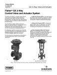
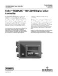
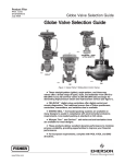
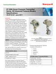
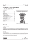
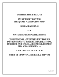
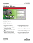
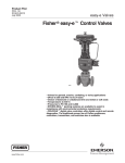
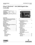
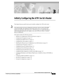
Product Bulletin GX Control Valve and Actuator 51.1:GX March 2012 D103171X012 Fisherr GX Control Valve and Actuator System The Fisher GX is a compact, state-of-the-art control valve and actuator system, designed to control a wide range of process liquids, gases, and vapors. The GX is rugged, reliable, and easy to select. It requires no actuator sizing -- the actuator selection is automatic once the valve body construction is selected. The optimized design results in reduced complexity and parts count. As a result, the cost of maintenance is reduced. The GX meets the requirements of both EN and ASME standards. It is available with a complete accessory package, including the Fisher FIELDVUEt DVC2000 integrated digital valve controller. Features Easy to size and select No actuator sizing required--selection is automatic W8861 Fisher GX Control Valve, Actuator, and DVC2000 Digital Valve Controller Optimized actuator allows for a wide range of air supply Valve body sizes DN 15 to DN 150 (NPS 1/2 through 6) Pressure Classes PN 10-40, CL150 and 300 Engineered for easy maintenance High capacity design Maximum part commonality across sizes Valve body flow passage optimized for flow stability Replaceable trim Full range of materials, including alloys Shutoff capabilities: Class IV, V, and VI Low lifetime costs Robust, low-profile design Rangeability of 50:1 (equal percentage) Compact multi-spring pneumatic actuator Optional metal bellows seal Available with integrated, easy-to-calibrate DVC2000 digital valve controller ISO 5210 F7 mounting available for use with electric actuators www.Fisher.com Product Bulletin GX Control Valve and Actuator 51.1:GX March 2012 D103171X012 Figure 1. Fisher GX Control Valve Assembly with Port-Guided Contoured Plug (Port Sizes 36 to 136 mm) COMPACT FIELD-REVERSIBLE MULTI-SPRING ACTUATOR INTEGRAL PNEUMATIC PASSAGEWAYS INTEGRATED POSITIONER MOUNTING NAMUR POSITIONER MOUNTING CAPABILITY ONE-PIECE SCREWED PACKING FOLLOWER STANDARD LIVE-LOADED PACKING CLAMPED BONNET DESIGN W8568-1A Optimized valve and actuator system. Product simplicity and ease of selection form the foundation of the GX. Mounted with a digital or analog positioner, the GX provides high performance control across a wide range of process applications. Compact actuator design. The GX utilizes a compact, multi-spring actuator. The GX design has been optimized to eliminate complicated actuator sizing procedures - once the valve body, port size, and air supply pressure are selected, the actuator size is fixed. Modular design. The design architecture has been optimized to maximize the use of common parts across sizes. The actuator stem and stem connector are used across all GX sizes. The GX actuator uses a total of 5 different springs across all valve sizes. These spring sets have been optimized to allow for maximum application coverage. The plug/stem assemblies and packing sets are common across several sizes, as well. Low lifetime costs. Reduced product complexity, low parts count, and part commonality all contribute to reduced inventory and maintenance costs. Contents Features . . . . . . . . . . . . . . . . . . . . . . . . . . . . . . . . . . . . . 1 Principle of Operation . . . . . . . . . . . . . . . . . . . . . . . . . 4 The Fisher GX Control Valve . . . . . . . . . . . . . . . . . . . . 6 Fisher GX Control Valve Specifications and Materials of Construction . . . . . . . . . . . . . . . . 7 GX Cavitrolt III for DN25 (NPS 1) through DN50 (NPS 2) . . . . . . . . . . . . . . . . . . . . . . . . . . . . . 14 GX Whisper Trimt III for DN80 (NPS 3) through DN150 (NPS 6) . . . . . . . . . . . . . . . . . . . . . . . . . . . . 14 The Fisher GX Diaphragm Actuator . . . . . . . . . . . . . 15 2 GX ISO 5210 Electric Actuator Mounting . . . . . . . . . Bellows Extension Bonnet . . . . . . . . . . . . . . . . . . . . . Valve-Actuator Dimensions and Weights . . . . . . . . Fisher GX Actuator Accessories . . . . . . . . . . . . . . . . . The Fisher FIELDVUE DVC2000 Digital Valve Controller . . . . . . . . . . . . . . . . . . . . . Optional Positioners and Instruments . . . . . . . . . . . Manual Handwheels . . . . . . . . . . . . . . . . . . . . . . . . . . Coefficients . . . . . . . . . . . . . . . . . . . . . . . . . . . . . . . . . 16 16 21 23 23 24 25 27 Product Bulletin GX Control Valve and Actuator 51.1:GX March 2012 D103171X012 Figure 2. Fisher GX and DVC2000 Digital Valve Controller Figure 3. Fisher GX Cryogenic Valve LINKAGE-LESS POSITION FEEDBACK DVC2000 COVER W8588 PUSH-BUTTON INSTRUMENT SETUP Stable flow control. The flow cavity of the GX valve body has been engineered to provide stable flow and reduce process variability. Live-loaded packing. The GX comes with live-loaded PTFE V-ring packing as standard. The live-loaded design helps to seal your process to conserve valuable process fluid, while reducing emissions to the environment. The long-life and high reliability of the live-loaded system also reduces maintenance costs and process downtime. For applications exceeding 232_C (450_F), live-loaded ULF (Ultra Low Friction) graphite packing and extension bonnets are available for all sizes except DN150. Easy maintenance. The simple screwed seat-ring and one-piece plug and stem design provide easy maintenance. Design simplicity and parts commonality contribute to reduced spares inventory. The integrated DVC2000 digital valve controller allows easy instrument removal, without a requirement for tubing disconnection or replacement (fail-down construction). Long life. Alloy valve constructions and hardened trim materials are available in the GX to increase valve body, bonnet, and trim life. W9343 Cryogenic offering. The GX is available in a low temperature construction (see figure 3). The compact design maintains high performance in low temperature applications, while minimizing overall envelope size. Digital valve controller. The GX is available with the DVC2000 digital valve controller. The DVC2000 is easy to use, compact, and designed for easy mounting. It converts a 4-20 mA input signal into a pneumatic output signal, which feeds the control valve actuator. Instrument setup is performed with a push button and liquid crystal display (LCD) interface. This interface is protected from the environment within a sealed enclosure. The interface supports multiple languages, including German, French, Italian, Spanish, Chinese, Japanese, Portuguese, Russian, Polish, Czech, Arabic, and English. Intrinsic safety and non-incendive construction is available to CSA, FM, ATEX, and IEC standards. An optional module provides integrated limit switches and a position transmitter. Integrated mounting. The DVC2000 digital valve controller integrally mounts to the GX actuator, eliminating the need for mounting brackets. The DVC2000 transmits a pneumatic signal to the actuator casing via an air passage in the yoke leg, causing the valve to stroke (see figure 4). This eliminates the need for positioner-to-actuator tubing in the fail-down configuration. 3 Product Bulletin GX Control Valve and Actuator 51.1:GX March 2012 D103171X012 Figure 4. Fisher GX Principle of Operation -- Actuator Air Supply AIR SUPPLY AIR VENT AIR VENT AIR SUPPLY FAIL-DOWN The DVC2000 mounting interface is identical on both sides of the actuator yoke for valve body sizes DN 15 through DN 100 (NPS 1/2 through 4). This symmetrical design allows the DVC2000 to be easily moved from one side of the valve to the other without the need to rotate the actuator. The DN 150 (NPS 6) yoke is not symmetrical. Linkage-less feedback. The DVC2000 digital valve controller offers as standard a non-contacting valve position feedback system. This is a true linkage-less design, which uses no levers and no touching parts between the valve stem and the positioner. Additional Accessory selection. The GX is available with a variety of digital or analog positioners besides 4 FAIL-UP the DVC2000, as well as solenoid and limit switches. The actuator is also compatible with the IEC 60534-6-1 (NAMUR) positioner mounting standard. Principle of Operation Integrated Air Supply. When mounted with the DVC2000 digital valve controller, the GX uses an integrated actuator air supply system. In the fail-down construction, air is supplied to the lower actuator casing via a port on the actuator yoke face -- no tubing is required. In the fail-up configuration, air is supplied to the upper casing via tubing. Product Bulletin GX Control Valve and Actuator 51.1:GX March 2012 D103171X012 Figure 5. Fisher GX Control Valve with Typical Soft Seat Trim Construction (Port Sizes of 22 - 136mm) PTFE SEAT SCREWED-IN SEAT RING W9023-1 PLUG Figure 6. Fisher GX Control Valve with Port-Guided Plug (Port Sizes of 36 - 136mm) VALVE BODIES AVAILABLE IN EN AND ASME PRESSURE RATINGS CLAMPED BONNET, WITH LIVE-LOADED PTFE PACKING AS STANDARD SCREWED-IN SEAT RING FLOW GEOMETRY ENGINEERED FOR STABLE FLOW AND REDUCED PROCESS VARIABILITY PORT-GUIDED PLUG DESIGN W8568-1 Figure 7. Fisher GX Control Valve with Balanced Trim (Port Sizes of 70, 90, and 136 mm Only) LIVE-LOADED PTFE PACKING SEAL RING BACKUP RING CONTOURED PLUG W8578-1 5 Product Bulletin GX Control Valve and Actuator 51.1:GX March 2012 D103171X012 Figure 8. Fisher GX Control Valve Assembly with Stem-Guided Contoured Plug (Size DN 25/1-Inch) COMPACT FIELD-REVERSIBLE MULTI-SPRING ACTUATOR INTEGRAL PNEUMATIC PASSAGEWAYS INTEGRATED POSITIONER MOUNTING NAMUR POSITIONER MOUNTING CAPABILITY ONE-PIECE SCREWED PACKING FOLLOWER STANDARD LIVE-LOADED PACKING CLAMPED BONNET DESIGN W8486-3 The Fisher GX Control Valve The GX is a single port, flow-up globe style valve that offers port-guided (figure 1), stem-guided (figure 8), and balanced trim with a screwed-in seat ring (see table 1 for a description of trim style availability). Each valve size offers an unbalanced plug design, which eliminates dead spaces where fluid polymerization might occur. Although the optimized GX actuator allows for wide usage of unbalanced trim, a balanced plug design is available for higher pressure drop applications in DN80, 100 and 150 (NPS 3, 4, and 6) sizes. The GX incorporates a clamped bonnet and an easy-to-adjust screwed packing follower (see figure 1). The plug and stem are a rugged, one-piece welded assembly. 6 The standard construction incorporates metal-to-metal seating, with a PTFE soft seat option for Class VI shutoff (see figure 5). Class V shutoff is available with metal trim. Hardened trim with stellite overlay is available for erosive service, as well. PTFE V-ring stem packing is standard with the GX. The live-loaded system provides excellent stem sealing and extended service life. Live-loaded graphite ULF packing and extension bonnets are available for high temperature applications. Both linear and equal percentage flow characteristics are available in full port and restricted trim. Micro-Flow is available for applications requiring low flow control capability. Standard valve body materials are carbon steel and stainless steel. Alloy materials are available for valve body sizes DN 15 through DN 100 (NPS 1/2 through 4) for highly corrosive applications. Product Bulletin GX Control Valve and Actuator 51.1:GX March 2012 D103171X012 Fisher GX Control Valve Specifications and Materials of Construction See tables 1 and 2. Table 1. Fisher GX Valve Specifications Specifications EN ASME Valve Body Size DN 15, 20, 25, 40, 50, 80, 100, 150 NPS 1/2, 3/4, 1, 1-1/2, 2, 3, 4, 6 Pressure Rating PN 10 / 16 / 25 / 40 per EN 1092-1 CL150 / 300 per ASME B16.34 End Connections Flanged raised face per EN 1092-1 Flanged raised face per ASME B16.5 Valve Body/Bonnet Materials 1.0619 steel ASME SA216 WCC steel 1.4409 stainless steel ASME SA351 CF3M stainless steel CW2M (sizes DN 25 through DN 100 only) CW2M (NPS 1 through 4 only) ASME SA352 LCC ASME SA352 LCC CN7M Alloy 20 (sizes DN 25 through DN 100 only) CN7M Alloy 20 (NPS 1 through 4 only) CDMN Duplex SST (sizes DN 25 through DN 100 only) CDMN Duplex SST (NPS 1 through 4 only) CF3 304L SST (sizes DN 25 through DN 100 only) CF3 304L SST (NPS 1 through 4 only) M35-2 (NPS 1 through 4 only) N7M Alloy B2 (NPS 1 through 4 only) Face-to-Face Dimensions Consistent with EN 558-1 Series 1 Shutoff per IEC 60534-4 and ANSI/FCI 70-2 Metal seat - Class V (optional) PTFE seat - Class VI (optional)(1) Flow Direction Flow-up (Cavitrol III trim, Flow down) Flow Control Characteristics Trim Style Consistent with ANSI/ISA 75.08.01 Metal seat - Class IV (standard) Equal Percentage and Linear Port Diameters Trim Style Description 4.8 mm Micro-Flow trim (unbalanced) 9.5, 14, 22 mm Stem-Guided with Contoured Plug (unbalanced) or Port-Guided with Cavitrol III trim (unbalanced) 36, 46 mm Port-Guided Plug (unbalanced) 70, 90, 136 mm Balanced Trim with Contoured plug or Unbalanced Port-Guided Plug Handwheel Available as an option Travel Stop Available as an option 1. For 4.8 to 14 mm ports, Class VI shutoff is achieved without PTFE seat. 7 Product Bulletin GX Control Valve and Actuator 51.1:GX March 2012 D103171X012 Table 2. Materials (Other Valve Components) Component Material Packing Follower S21800 SST screwed follower SA193-B7 studs / SA194-2H nuts with NCF2 coating for carbon steel and stainless steel constructions Body/Bonnet Bolting and Nuts DN 15 through DN 100: S20910 (XM19) for alloy (standard) and stainless steel assemblies (optional) DN 150: SA193-B7M studs / SA194-2HM nuts with NCF2 coating (optional) Live-loaded PTFE V-ring (standard) with N07718 Belleville springs Packing Live-loaded Graphite ULF (optional) with N07718 Belleville springs DN 15 through DN 150: Graphite laminate Bonnet Gasket DN 15 through DN 100: PTFE encapsulated N10276 (optional) Applicable from -46 to 232_C (-50 to 450_F) (May be preferable when the standard graphite laminate gasket material is not compatible with the process fluid) Stainless steel, or carbon steel valve bodies and bonnets NACE MR0175/ISO15156(1) DN 15 through DN 100 and NACE MR0103 Construction DN 150 SA193-B7 studs / SA194-2H nuts with NCF2 coating (S20910 SST optional) body/bonnet bolting Standard live-loaded PTFE packing S31603/CoCr-A plug, S20910 stem, and S31603/CoCr-A seat ring SA193-B7M studs / SA194-2HM nuts with NCF2 coating Carbon-Filled PTFE Seal Ring Balanced Trim (Sizes DN 80, 100, and 150 / NPS 3, 4, and 6) Nitrile (Standard) -46 to 82_C (-50 to 180_F) Ethylene Propylene [EPDM] (Optional): -46 to 232_C (-50 to 450_F) in steam and hot water; -46 to 121_C (-50 to 250_F) in air (EPDM is not recommended for use in hydrocarbons) Back-up Rings FKM (fluorocarbon) (Optional): -18 to 204_C (0 to 400_F) (Applicable in a wide variety of solvents, chemicals, and hydrocarbons. Avoid use with steam, ammonia, or hot water over 82_C [180_F]) 1. Environmental restrictions may apply. Table 3. Trim Materials for Port Diameters of 4.8 mm (Micro-Flow trim) (Unbalanced Trim) Valve Body Construction Carbon steel (1.0619 / WCC and LCC) Stainless steel (1.4409 / CF3M) Trim Type Stem Plug Seat Metal to metal S31603 strain hardened R31233 SA351 CF3M SA351 CF3M / CoCr-A seat Hard-faced S31603 strain hardened R31233 Metal to metal N06022 R31233 CW2M Metal to metal S31603 strain hardened R31233 SA351 CF3M Hard-faced S31603 strain hardened R31233 SA351 CF3M / CoCr-A seat Metal to metal N06022 R31233 CW2M CW2M/CN7M(1) Metal to metal N06022 R31233 CW2M Duplex SST (CD3MN)(1) Metal to metal S31803 (Duplex SST) R31233 CD3MN (Duplex SST) 304L SST (CF3)(1) Metal to metal S31803 (Duplex SST) R31233 CF3 (304L SST) 1. Not available in DN 15 and DN 20 (NPS 1/2 and 3/4) sizes. Table 4. Trim Materials for Port Diameters of 9.5 and 14 mm (Unbalanced Trim) Valve Body Construction Carbon steel (1.0619 / WCC and LCC) Stainless steel (1.4409 / CF3M) Trim Type Stem Plug Seat Metal to metal S31603 strain hardened S31603 SA351 CF3M SA351 CF3M / CoCr-A seat Hard-faced S20910 S31603 / CoCr-A seat Metal to metal N06022 N06022 CW2M Metal to metal S31603 strain hardened S31603 SA351 CF3M Hard-faced S20910 S31603 / CoCr-A seat SA351 CF3M / CoCr-A seat Metal to metal N06022 N06022 CW2M Carbon steel to NACE MR0175/ISO15156(2) and NACE MR0103 (1.0619 / WCC) Hard-faced S20910 S31603 / CoCr-A seat SA351 CF3M / CoCr-A seat Stainless steel to NACE MR0175/ISO15156(2) and NACE MR0103 (1.4409 / CF3M) Hard-faced S20910 S31603 / CoCr-A seat SA351 CF3M / CoCr-A seat CW2M/CN7M(1) Metal to metal N06022 N06022 CW2M Duplex SST (CD3MN)(1) Metal to metal S31803 (Duplex SST) S31803 (Duplex SST) CD3MN (Duplex SST) 304L SST (CF3)(1) Metal to metal S31803 (Duplex SST) S30403 (304L SST) CF3 (304L SST) M35-2(1) Metal to metal N05500 N05500 N05500 N7M (Alloy B2)(1) Metal to metal N10665 (Alloy B2) N10665 (Alloy B2) N7M (Alloy B2) 1. Not available in DN 15 and DN 20 (NPS 1/2 and 3/4) sizes. 2. Environmental restrictions may apply. 8 Product Bulletin GX Control Valve and Actuator 51.1:GX March 2012 D103171X012 Table 5. Trim Materials for Port Diameters of 22, 36, 46, 70, 90, and 136 mm (Unbalanced Trim) Valve Body Construction Trim Type Stem Plug Seat Metal to metal S31603 strain hardened S31603 SA351 CF3M(3) Soft seat S31603 strain hardened S31603 SA351 CF3M / PTFE seat(4) S20910 S31603 / CoCr-A seat SA351 CF3M/CoCr-A seat (22 mm) SA351 CF3M/CoCr-A seat and guide (>22 mm) Cavitrol III trim S20910 S31603/CoCr-A seat S17400 Cage Metal to metal N06022 N06022 CW2M(1) Soft seat N06022 N06022 CW2M / PTFE seat(1) Metal to metal S31603 strain hardened S31603 SA351 CF3M(3) Soft seat S31603 strain hardened S31603 SA351 CF3M / PTFE seat(4) S20910 S31603 / CoCr-A seat SA351 CF3M/CoCr-A seat (22 mm) SA351 CF3M/CoCr-A seat and guide (>22 mm) Cavitrol III trim S20910 S31603/CoCr-A seat and guide S17400 Cage Metal to metal N06022 N06022 CW2M(1) Soft seat N06022 N06022 CW2M / PTFE seat(1) Carbon steel to NACE MR0175/ISO15156(5) and NACE MR0103 (1.0619 / WCC) Hard-faced S20910 S31603 / CoCr-A seat SA351 CF3M/CoCr-A seat (22 mm) SA351 CF3M/CoCr-A seat and guide (>22 mm) Stainless steel to NACE MR0175/ISO15156(5) and NACE MR0103 (1.4409 / CF3M) Hard-faced S20910 S31603 / CoCr-A seat SA351 CF3M/CoCr-A seat (22 mm) SA351 CF3M/CoCr-A seat and guide (>22 mm) Metal to metal N06022 N06022 CW2M Soft seat N06022 N06022 CW2M / PTFE seat Metal to metal S31803 (Duplex SST) S31803 (Duplex SST) CD3MN (Duplex SST) Soft seat S31803 (Duplex SST) S31803 (Duplex SST) CD3MN (Duplex SST)/ PTFE seat(1) Metal to metal S31803 (Duplex SST) S30403 (304L SST) CF3 (304L SST) S30403 (304L SST) CF3 (304L SST)/ PTFE seat(1) Carbon steel (1.0619 / WCC and LCC) Stainless steel (1.4409 / CF3M) CW2M(1)/CN7M(1) Duplex SST (CD3MN)(1) 304L SST (CF3)(1) M35-2(1) N7M (Alloy B2)(1) Hard-faced/ Whisper Trim III(2) Hard-faced/ Whisper Trim III(2) Soft seat S31803 (Duplex SST) Metal to metal N05500 N05500 N05500 N10665 (Alloy B2) N10665 (22 mm)/ N7M (>22 mm) N7M (Alloy B2) Metal to metal 1. Not available for DN 150 (NPS 6). 2. Whisper Trim III is only available in 70 and 90 mm ports. 3. DN150 (NPS 6) has CoCr-A seat and guide. 4. DN150 (NPS 6) has CoCr-A guide. 5. Environmental restrictions may apply. Table 6. Trim Materials for Port Diameters of 70, 90, and 136 mm (Balanced Trim)(3) Valve Body Construction Trim Type Stem Plug Seat Metal to metal S31603 strain hardened S31603 SA351 CF3M Hard-faced/ Whisper Trim III(4) S20910 S31603 / CoCr-A seat and guide SA351 CF3M / CoCr-A seat and guide Metal to metal N06022 N06022 CW2M(2) Metal to metal S31603 strain hardened S31603 SA351 CF3M Hard-faced/Whisper Trim III(4) S20910 S31603 / CoCr-A seat and guide SA351 CF3M / CoCr-A seat and guide Metal to metal N06022 N06022 CW2M(2) Carbon steel to NACE MR0175/ISO15156(5) and NACE MR0103 (1.0619 / WCC) Hard-faced S20910 S31603 / CoCr-A seat SA351 CF3M / CoCr-A seat and guide Stainless steel to NACE MR0175/ISO15156(5) and NACE MR0103 (1.4409 / CF3M) Hard-faced S20910 S31603 / CoCr-A seat SA351 CF3M / CoCr-A seat and guide Carbon steel (1.0619 / WCC and LCC)(1) Stainless steel (1.4409 / CF3M) CW2M(2) / CN7M(2) Metal to metal N06022 N06022 CW2M Duplex SST (CD3MN)(2) Metal to metal S31803 (Duplex SST) S31803 (Duplex SST) CD3MN (Duplex SST) 304L SST (CF3)(2) Metal to metal S31803 (Duplex SST) S30403 (304L SST) CF3 (304L SST) 1. The bonnet used in the carbon steel balanced trim construction is made of 1.4409/CF3M stainless steel. 2. Not available for DN 150 (NPS 6). 3. Balanced trim not available with M35-2 or N7M trim. 4. Balanced Whisper Trim III in DN150 (NPS 6) 136 mm port diameter only. 5. Environmental restrictions may apply. 9 Product Bulletin GX Control Valve and Actuator 51.1:GX March 2012 D103171X012 Table 7. Allowable Temperature Ranges for Valve Body, Bonnet and Trim(1) VALVE BODY / BONNET MATERIAL 1.0619/SA216 WCC Steel PACKING Standard PTFE or Graphite ULF Extension Bellows 1.4409/SA351 CF3M SST TEMPERATURE BONNET STYLE TRIM STYLE _C _F Min Max Min Max Graphite laminate or PTFE / N10276 Metal to metal; hard-faced; soft seat -29 232 -20 450 Graphite ULF Graphite laminate Metal to metal; hard-faced -29 371 -20 700 PTFE Graphite laminate or PTFE / N10276 Metal to metal; hard-faced; soft seat -29 232 -20 450 PTFE Graphite laminate Metal to metal; hard-faced -29 371 -50 700 Standard PTFE or Graphite ULF Graphite laminate or PTFE / N10276 Metal to metal; hard-faced; soft seat -46 232 -50 450 Extension Graphite ULF Graphite laminate Metal to metal; hard-faced -46 371 -50 700 Cryogenic Extension PTFE or Graphite ULF Graphite laminate Metal to metal; hard-faced (3) 371 (3) 700 PTFE Graphite laminate or PTFE / N10276 Metal to metal; hard-faced; soft seat -46 232 -50 450 PTFE Graphite laminate Metal to metal; hard-faced -46 371 -50 700 Standard PTFE Graphite laminate or PTFE / N10276 Metal to metal; soft seat -46(2) 232 -50(2) 450 Bellows PTFE Graphite laminate or PTFE / N10276 Metal to metal; soft seat -46(2) 232 -50(2) 450 Standard PTFE or Graphite ULF Graphite laminate or PTFE / N10276 Metal to metal; hard-faced; soft seat -46 232 -50 450 Extension Graphite ULF Graphite laminate Metal to metal; hard-faced -46 343 -50 650 PTFE Graphite laminate or PTFE / N10276 Metal to metal; hard-faced; soft seat -46 232 -50 450 PTFE Graphite laminate Metal to metal; hard-faced -46 343 -50 650 Metal to metal; soft seat -46(2) 232 -50(2) 450 Bellows CW2M LCC GASKET Bellows CN7M Standard PTFE Graphite laminate or PTFE / N10276 304L SST (CF3) Standard PTFE Graphite laminate or PTFE / S30403 Metal to metal; soft seat -46(2) 232 -50(2) 450 Duplex SST (CD3MN) Standard PTFE Graphite laminate or PTFE / N10276 Metal to metal; soft seat -46(2) 232 -50(2) 450 Metal to metal -46(2) 232 -50(2) 450 Metal to metal -46(2) 232 -50(2) 450 M35-2 Standard PTFE Graphite laminate or PTFE / N04400 N7M (Alloy B2) Standard PTFE Graphite laminate or PTFE / N10276 1. Back-up ring materials used in Sizes DN 80 and 100 (NPS 3 and 4) with balanced trim may be limited by temperature and application. See table 2. 2. Minimum allowable temperature for PN series flanges is -10_C (14_F). 3. Consult your Emerson Process Management sales office for minimum temperature limit. 10 Product Bulletin GX Control Valve and Actuator 51.1:GX March 2012 D103171X012 Figure 9. Material Pressure/Temperature Curves 1 E1026 E1140 1. N7M is only offered with CL150 and CL300 (not PN10, PN16, PN25, or PN40). 11 Product Bulletin GX Control Valve and Actuator 51.1:GX March 2012 D103171X012 Figure 10. Material Pressure/Temperature Curves 1 1 E0901 1. CD3MN, CN7M, and M35-2 are not listed in EN 12516-1. The PN designations are used only to indicate relative pressure-retaining capabilities. 12 1 Product Bulletin GX Control Valve and Actuator 51.1:GX March 2012 D103171X012 Figure 11. Fisher GX Packing BELLEVILLE SPRING PACK BELLEVILLE SPRING PACK PACKING SPACER PACKING SPACER ANTI-EXTRUSION WASHER PACKING RINGS PACKING SET ANTI-EXTRUSION WASHER PACKING BOX RING PACKING BOX RING E0897 STANDARD BONNET WITH PTFE PACKING SET DN15 through DN150 (NPS 1/2 through 6) BELLEVILLE SPRING PACK PACKING SPACER PACKING RINGS PACKING BOX RING GE03755_23 STANDARD BONNET WITH GRAPHITE ULF PACKING SET DN150 only (NPS 6 only) EXTENSION BONNET WITH GRAPHITE ULF PACKING SET DN15 through DN100 (NPS 1/2 through 4) 13 Product Bulletin GX Control Valve and Actuator 51.1:GX March 2012 D103171X012 Figure 12. GX Cavitrol III Trim Figure 13. GX Whisper Trim III GX Cavitrol III for DN25 (NPS 1) through DN50 (NPS 2) Cavitrol III trim lowers hydrodynamic noise and reduces vibration by utilizing proprietary drilled hole shape and spacing to shift the frequency and isolate the cavitation in order to prevent damage. Cavitrol III 1stage technology is used without altering the integral GX bonnet design. GX Whisper Trim III for DN80 (NPS 3) through DN150 (NPS 6) Whisper Trim III A1 lowers aerodynamic valve noise by utilizing multiple orifices of special shape, size, and spacing. These orifices break up turbulent compressible fluid streams and shift the acoustic energy to a higher frequency range. The result is about 20 dBA noise attenuation. Features Max deltaP of 400 psid Features Flow down Flow up Class V shutoff — standard Class IV shutoff Available Sizes Available Sizes NPS 1, 225 Actuator, 20mm travel NPS 1-1/2, 750 Actuator, 20mm travel NPS 2, 750 Actuator, 20mm travel Requirements NPS 3, 750 Actuator, 40mm travel NPS 4, 750 Actuator, 40mm travel NPS 6, 1200 Actuator, 60mm travel Table 9. Materials of Construction for Whisper Trim III(1) Minimum 4 bar supply pressure Only available with standard bonnet Table 8. Materials of Construction for Cavitrol III Trim 14 Part Material Stem S20910 Plug S31603 / CoCr-A Seat and Guide Seat Ring / Cage S17400 Part Material Stem S20910 Plug S31603 / CoCr-A Seat Seat Ring S31603 / CoCr-A Seat and Guide Cage(1) CF3M 1. NPS 6 uses a separate cage, not integral to the plug stem. Allowable temperature ranges are shown in table 7. Product Bulletin GX Control Valve and Actuator 51.1:GX March 2012 D103171X012 The Fisher GX Diaphragm Actuator The GX uses a multi-spring, pneumatic diaphragm actuator (see figure 14). It is capable of air supply pressures to 6.0 barg (87 psig), allowing valve shutoff at high pressure drops. Figure 14. Fisher GX Actuator The GX product selection system automatically matches the actuator to the valve, eliminating the need for complex actuator sizing procedures. The multiple spring design provides the preload, eliminating the need for bench set adjustment. The actuator is available in spring-to-open and fail-down configurations. The GX actuator can be used for throttling or on-off service. The GX is available with the integrated DVC2000 digital valve controller. Other digital and analog positioners are available, as well as optional solenoids and limit switches. W8487-3 Table 10. Actuator Specifications Description Pneumatic spring-return diaphragm actuator Operating Principle Air-to-open (standard) Air-to-close (optional) Operating Pressure Ranges 2.0 to 6.0 barg (29 to 87 psig)(1) Ambient Temperature -46 to 82_C (-50 to 180_F) Pressure Connection (Fail-up Construction) G 1/4 female casing connection Finish Powder coat polyester 1. May vary depending on construction (see bulletin 51.1:GX(S1)) Table 11. Materials of Construction Part Material Upper and Lower Casings AISI 1010 stamped carbon steel Springs Steel Diaphragm Nitrile and nylon Diaphragm Plate Size 225 and 750: AISI G10100 stamped carbon steel Size 1200: Cast carbon steel Yoke Carbon steel (stainless steel optional for some sizes) Casing Fasteners A2-70 stainless steel bolts and nuts Actuator Rod Stainless steel Stem Connector CF3M Stem Connector Fasteners SA193-B7 bolts with NCF2 coating Stem Bushing High-density polyethylene (HDPE) Stem Seal Nitrile 15 Product Bulletin GX Control Valve and Actuator 51.1:GX March 2012 D103171X012 Actuator Selection Thrust limitations apply when sizing electric actuators (see table 13). With the GX, actuator selection has never been easier. Once the valve size and port diameter have been determined, the actuator is automatically selected. No spring selection or bench set calculations are required. Mounting offering can be engineered if not already available for a selected actuator. Electric actuator mounting is not available for DN150, NPS 6 GX valves. For additional information, contact your Emerson Process Management sales office. The majority of GX constructions (both fail-down and fail-up) are rated to a full pressure class shutoff capability of 51.7 bar (750 psi) for a 4 to 6 bar (58 to 87 psig) actuator air supply. Refer to Fisher bulletin 51.1:GX (S1) for additional information. Bellows Extension Bonnet The GX actuator has been optimized to allow for varying ranges of supply pressure. See table 12. The GX bellows extension bonnet provides reliable and tight stem sealing for those applications where emissions escaping to the environment cannot be tolerated (see figure 15). The GX bellows is available in SST (1.4571 / 316Ti) or N10276 and covers a full range of valve sizes from DN 15 through DN 100 (NPS 1/2 through 4) (see tables 14 and 15). Table 12. Fisher GX Actuator Supply Pressure Ranges SUPPLY PRESSURE RANGE Bar Psig Standard 4.0 to 6.0 58 to 87 Optional 3.0 to 4.0 44 to 58 Optional 2.0 to 3.0 29 to 44 The GX bellows system has been designed for 100,000 full-travel cycles at maximum allowable pressure and ambient temperature (20_C [68_F]). GX ISO 5210 Electric Actuator Mounting The mechanically-formed metal bellows provides high operating reliability and extended cycle life (see tables 16, 17, and 18 for details). Electric actuator mounting is available for any manufacturing models that comply with ISO 5210, Flange type F7. The mounting offering includes a GX yoke, actuator rod adaptor, spacer, and bolting. The GX bellows design incorporates a rugged doubleor triple-wall construction for added security. Each bellows has been tested with helium before it leaves the factory. CAUTION The GX bellows bonnet comes standard with a live-loaded, PTFE packing system as a security backup. A connection is provided above the bellows to allow purging or monitoring the integrity of the replaceable bellows. The up travel stop must be set in the electric actuator in order to prevent damage to the valve trim. Table 13. Fisher GX Maximum Allowable Thrust for use with ISO 5210 Electric Actuators VALVE SIZE DN15-DN50 (NPS 1/2 to 2) DN80-DN100 (NPS 3 to 4) STEM DIAMETER TRAVEL mm mm Plain 10 20 Bellows/Extension Plain 14 20, 40 1. High strength stem materials consist of S20910, N05500, S31603 2. Low strength stem materials consist of S31803, N10665, N06022 16 BONNET STYLE Bellows/Extension MAXIMUM THRUST STEM MATERIAL STRENGTH N lbf High(1) 17000 3820 Low(2) 7600 1710 High 11400 2560 Low 6700 1500 High 20000 4500 Low 20000 4500 High 20000 4500 Low 14500 3260 Product Bulletin GX Control Valve and Actuator 51.1:GX March 2012 D103171X012 Figure 15. Fisher GX Bellows Bonnet and Selection Process Bellows Selection Process PACKING FOLLOWER BONNET LIVE-LOADED PTFE PACKING PURGE / MONITORING CONNECTION Follow this process to assist in selecting the appropriate bellows for the application. Step 1 Size and select the GX control valve that is appropriate for the application. This will identify the: S Valve body size S Actuator size S Orifice size STrim style (balanced or unbalanced) S Valve body material BELLOWS NUT BELLOWS GASKET BELLOWS/STEM ASSEMBLY EXTENSION BONNET BUSHING Step 2 Confirm bellows availability from table 14. Step 3 Using table 15, select the bellows material combination that is appropriate for the application. Using the temperature limits shown in table 7, confirm the selected construction is appropriate for the application temperatures. BODY/BONNET GASKET Step 4 VALVE PLUG Using bulletin 51.1:GX(S1), verify the application pressure drop does not exceed the actuator capability. Step 5 W8958-1 Using figure 16, check to ensure the maximum process pressure and temperature do not exceed the pressuretemperature rating of the selected bellows. 17 Product Bulletin GX Control Valve and Actuator 51.1:GX March 2012 D103171X012 Table 14. Fisher GX Constructions with Bellows Availability VALVE BODY SIZES PORT SIZE (mm) ACTUATOR SIZES PLUG TRAVEL TRIM STYLE DN15-50 (NPS 1/2 to 2) 4.8 to 46 225 and 750 20 mm Unbalanced DN80 (NPS 3) 36 to 46 750 20 mm Unbalanced 70 750 20 mm Balanced DN100 (NPS 4) 46 750 20 mm Unbalanced 90 750 20 mm Balanced Table 15. Bellows Materials of Construction Valve Body / Bonnet Carbon Steel (1.0619/WCC and LCC) Stainless Steel (1.4409/CF3M) CW2M Bellows Bellows Stem Extension Trim Materials Plug(1) Stem Material Packing Gaskets Lower Bushing Monitoring Connection Plug SST (1.4571/316Ti) S31603 S31603 or CF3M S31603 SA193-B7 with NCF2 coating Live-loaded PTFE Graphite laminate S31600 with R31233 insert S31600 N10276 S31603 S31603 or CF3M S31603 SA193-B7 with NCF2 coating Live-loaded PTFE Graphite laminate S31600 with R31233 insert S31600 N10276 N06022 N06022 or CW2M N06022 S20910 Live-loaded PTFE Graphite laminate N10276 with R31233 insert N10276 SST (1.4571/316Ti) S31603 S31603 or CF3M S31603 S20910 Live-loaded PTFE Graphite laminate S31600 with R31233 insert S31600 N10276 S31603 S31603 or CF3M S31603 S20910 Live-loaded PTFE Graphite laminate S31600 with R31233 insert S31600 N10276 N06022 N06022 or CW2M N06022 S20910 Live-loaded PTFE Graphite laminate N10276 with R31233 insert N10276 N10276 N06022 N06022 or CW2M N06022 S20910 Live-loaded PTFE Graphite laminate N10276 with R31233 insert N10276 1. Plug material for the 4.8 mm port is R31233. For bellows height dimensions, see table 20. 18 Bolting Product Bulletin GX Control Valve and Actuator 51.1:GX March 2012 D103171X012 Cycle Life Bellows service life is affected by several factors, including process pressure, temperature, and plug travel. Tables 16, 17, 18, and 19 provide estimates of cycle life for several cases. Table 16. Estimated Bellows Cycle Life at 10.3 bar (150 psig) and 20_C (68_F) VALVE SIZE DN15-50 (NPS 1/2 to 2) DN80-100 (NPS 3 to 4) STEM SIZE PROCESS TEMPERATURE _C _F ESTIMATED CYCLE LIFE (50% Stroke [25-75% travel]) BELLOWS MATERIAL PLYS BELLOWS PRESSURE 1.4571 (316Ti) 2 10.3 bar (150 psig) 20 68 1,040,000 N10276 3 10.3 bar (150 psig) 20 68 910,000 1.4571 (316Ti) 2 10.3 bar (150 psig) 20 68 1,020,000 N10276 2 10.3 bar (150 psig) 20 68 980,000 10mm 14mm Table 17. Estimated Bellows Cycle Life at Bellows Maximum Allowable Pressure and 20_C (68_F) VALVE SIZE DN15-50 (NPS 1/2 to 2) DN80-100 (NPS 3 to 4) STEM SIZE BELLOWS MATERIAL PLYS MAXIMUM ALLOWABLE BELLOWS PRESSURE(1) PROCESS TEMPERATURE _C _F ESTIMATED CYCLE LIFE (50% Stroke [25-75% travel]) 1.4571 (316Ti) 2 40 bar (580 psig) 20 68 830,000 N10276 3 51.7 bar (750 psig) 20 68 800,000 1.4571 (316Ti) 2 45 bar (650 psig) 20 68 800,000 N10276 2 51.7 bar (750 psig) 20 68 810,000 10mm 14mm 1. Valve maximum allowable pressure drop may be limited by size and material. See GX bulletin 51.1:GX(S1) for additional information. Table 18. Estimated Bellows Cycle Life at Bellows Maximum Allowable Pressure and 232_C (450_F) VALVE SIZE DN15-50 (NPS 1/2 to 2) DN80-100 (NPS 3 to 4) STEM SIZE PLYS MAXIMUM ALLOWABLE BELLOWS PRESSURE(1) _C _F 1.4571 (316Ti) 2 29.8 bar (430 psig) 232 450 410,000 N10276 3 47.2 bar (685 psig) 232 450 560,000 1.4571 (316Ti) 2 33.5 bar (485 psig) 232 450 390,000 N10276 2 47.2 bar (685 psig) 232 450 550,000 BELLOWS MATERIAL 10mm 14mm PROCESS TEMPERATURE ESTIMATED CYCLE LIFE (50% Stroke [25-75% travel]) 1. Valve maximum allowable pressure drop may be limited by size and material. See GX bulletin 51.1:GX(S1) for additional information. Table 19. Estimated Bellows Cycle Life at Bellows Maximum Allowable Pressure and 371_C (700_F) VALVE SIZE DN15-50 (NPS 1/2 to 2) DN80-100 (NPS 3 to 4) STEM SIZE PROCESS TEMPERATURE _C _F BELLOWS MATERIAL PLYS MAXIMUM ALLOWABLE BELLOWS PRESSURE 1.4571 (316Ti) 2 26.1 bar (380 psig) 371 700 250,000 N10276 3 39.3 bar (570 psig) 371 700 430,000 1.4571 (316Ti) 2 29.3 bar (425 psig) 371 700 240,000 2 39.3 bar (570 psig) 371 700 430,000 10mm 14mm N10276 ESTIMATED CYCLE LIFE (50% Stroke [25-75% travel]) 19 Product Bulletin GX Control Valve and Actuator 51.1:GX March 2012 D103171X012 Bellows Pressure - Temperature Ratings See figure 16. Figure 16. Bellows Pressure - Temperature Ratings Pressure-Temperature Ratings for 1.4571 (316Ti) Bellows Pressure-Temperature Ratings for N10276 Bellows 20 Product Bulletin GX Control Valve and Actuator 51.1:GX March 2012 D103171X012 Valve-Actuator Dimensions and Weights See figure 17 and table 20. Figure 17. Fisher GX Dimensions (also see table 20) AR E D F C A/2 W8486-3 A GX STEM-GUIDED CONSTRUCTION (DN25 / NPS 1) Table 20. Fisher GX Dimensions and Weights A VALVE SIZE PORT DIA ACTUATOR SIZE mm C D TOTAL WEIGHT Extended or Bellows Bonnet Actuator Height (Standard Bonnet) Actuator Height (Extended or Bellows Bonnet) With Standard Bonnet With Extended or Bellows Bonnet mm kg kg E Casing Dia F (AR) Removal Height(3) PN10/ 16 & PN25/ 40 CL150 CL300 Standard Bonnet mm mm mm mm mm mm mm mm DN 15/ NPS 1/2 4.8, 9.5 225 130 184 190 66 304 313 313 270 115 21 25 DN 20/ NPS 3/4 4.8, 9.5, 14 225 150 184 194 66 304 313 313 270 115 22 26 DN 25/ NPS 1 4.8, 9.5, 14, 22 225 160 184 197 58 296 313 313 270 115 22 26 14, 22, 36 225 200 222 235 62 300 313 313 270 115 25 29 DN 40/ NPS 1-1/2 DN 50/ NPS 2 DN 80/ NPS 3 DN 100/ NPS 4 DN 150/ NPS 6 36 750 200 222 235 62 300 342 342 430 115 52 56 22, 36, 46 225 230 254 267 68 306 313 313 270 115 29 33 36, 46 750 230 254 267 68 306 342 342 430 115 56 60 36, 46 750 310 298 318 105 373 375 375 430 125 79 88 70(1) 70 750 750 310 310 298 298 318 318 105 105 373(4) 373 375 395 375 395 430 430 125 125 81 83 90 92 46 70 750 750 350 350 352 352 368 368 121 121 393 393 379 399 375 395 430 430 130 130 98 101 109 111 90(2) 90(1) 750 350 352 368 121 393(4) 379 375 430 130 105 115 90 750 350 352 368 121 393 399 395 430 130 101 111 136 136(1) 136(5) 1200 1200 1200 480 480 480 451 451 451 473 473 473 189 200 230 ------- 559 559 589 ------- 566 566 566 224 210 240 235 247 247 ------- 1. Balanced trim design. 2. Balanced trim with reduced-capacity plug. 3. Clearance required for removing actuator from installed valve body. 4. Bellows bonnets are available for these constructions. However, extension bonnets are not available with balanced trim due to temperature limitations of the trim seals. 5. Severe service. 21 Product Bulletin GX Control Valve and Actuator 51.1:GX March 2012 D103171X012 Figure 18. Fisher GX Electric Actuator Mounting Dimensions (also see table 21) H G GE54731-1 GX ELECTRIC ACTUATOR MOUNTING Table 21. Fisher GX Electric Actuator Mounting Dimensions and Weights GX ELECTRIC ACTUATOR MOUNTING WEIGHT PORT DIAMETER G H mm mm mm With Standard Bonnet kg DN 15/ NPS 1/2 4.8, 9.5 202 176 12 16 DN 20/ NPS 3/4 4.8, 9.5, 14 202 176 13 17 DN 25/ NPS 1 4.8, 9.5, 14, 22 202 176 13 17 16 20 15 19 20 24 19 23 42 51 44 43 53 52 61 61 72 71 65 75 64 74 VALVE SIZE DN 40/ NPS 1-1/2 DN 50/ NPS 2 14, 22, 36 36 22, 36, 46 36, 46 202 202 176 176 36, 46 DN 80/ NPS 3 70(1) 70 222 176 46 70 DN 100/ NPS 4 90(2) 90(1) 90 1. Balanced trim design. 2. Balanced trim with reduced-capacity plug. 3. Severe service. 22 226 176 With Extension or Bellow Bonnet kg Product Bulletin GX Control Valve and Actuator 51.1:GX March 2012 D103171X012 Table 22. Positioner Selection Guidelines Digital I/P(1) DVC2000 X X DVC6200 X X 3661 I/P(2) P/P(3) Intrinsic Safety(4) Type X 3660 Flameproof / Explosionproof(4) Non- Incendive(4) X X X X X X 1. Digital I/P - microprocessor based electro-pneumatic with HART communication. 2. I/P - electro-pneumatic 3. P/P - pneumatic 4. Refer to Fisher bulletin 9.2:001 for instrument hazardous area classification details. Fisher GX Actuator Accessories Figure 19. Fisher FIELDVUE DVC2000 Digital Valve Controller The GX is available with a variety of pneumatic (P/P), electro-pneumatic (I/P), and digital valve positioners, as well as limit switches and solenoids. Table 22 provides the basic features of the positioners offered with the GX actuator. The Fisher FIELDVUE DVC2000 Digital Valve Controller The DVC2000 digital valve controller (figure 19) is simple to use, compact, and designed for the GX control valve. It converts a 4-20mA input signal into a pneumatic output signal, which feeds the control valve actuator. Instrument setup is performed with a pushbutton and liquid crystal display (LCD) interface. This interface is protected from the environment within an IP66 enclosure. Multiple languages are supported with the local interface including German, French, Italian, Spanish, Chinese, Japanese, Portuguese, Russian, Polish, Czech, Arabic, and English. Additionally, HARTr communication is supported over the 4-20mA loop wiring. The DVC2000 is designed to be integrally mounted to the GX actuator, avoiding the need for mounting brackets. The DVC2000 mounts directly to an interface pad on the actuator yoke leg with a secure 3-point mounting. An internal passage inside the yoke leg transmits the pneumatic signal to the actuator casing, eliminating the need for external tubing (in the air-to-open configuration). W8755 The high-performance linkage-less position feedback system eliminates physical contact between the valve stem and the digital valve controller or instrument. There are no wearing parts so cycle life is maximized. Additionally, the elimination of levers and linkages reduces the number of mounting parts and the mounting complexity. Digital valve controller or instrument replacement and maintenance is simplified because the feedback parts stay connected to the actuator. The DVC2000 is available with an optional module which includes two (2) integral limit switches and a stem position transmitter. The limit switches are configurable for open and closed valve indication. The position transmitter provides a 4-20mA signal for valve position feedback verification. As an integral component to the instrument, this option module avoids the need for difficult-to-mount external switches and transmitters. Designed to meet intrinsic safety and non-incendive requirements, this instrument delivers scalable functionality and high performance in a small package. 23 Product Bulletin GX Control Valve and Actuator 51.1:GX March 2012 Optional Positioners and Instruments D103171X012 Figure 20. Fisher GX Valve with 3660 or 3661 Posi tioner, NAMUR Mounting (IEC 60534-6-1) Fisher 3660 and 3661 Valve Positioners The 3660 pneumatic and 3661 electro-pneumatic positioners are rugged, accurate, and feature low steady-state air consumption. Designed to meet intrinsic safety requirements, these positioners offer simple functionality in a small package. (See figure 20 and table 22.) W8590 Fisher FIELDVUE DVC6200 Digital Valve Controller The DVC6200 digital valve controller is a communicating, microprocessor-based current-to-pneumatic instrument. Using HART or FOUNDATIONt fieldbus communication protocol, access to critical instrument, valve, and process conditions is provided. When used with ValveLinkt software, valve diagnostic tests can be run while the valve is in service to advise you of the performance of the entire control valve assembly. Designed to meet a broad range of hazardous area classifications, this instrument offers maximum functionality to improve your process performance. (See figure 21 and table 22.) 24 Figure 21. Fisher FIELDVUE DVC6200 Digital Valve Controller W9713 Product Bulletin GX Control Valve and Actuator 51.1:GX March 2012 D103171X012 Manual Handwheels actuators. Dimensions are provided in figure 23 and table 23. The GX is available with an optional, side-mounted manual handwheel (see figure 22). These handwheels provide a robust method of manually operating the valve in an emergency or upon loss of instrument air. When mounted to a fail-up actuator, rotating the handwheel clockwise moves the stem downwards. When mounted to a fail-down actuator, turning the handwheel in the clockwise direction causes the stem to move upwards. Disengagement of the handwheel to allow automatic operation is accomplished by simply rewinding the handwheel. The GX handwheel will stroke the valve up to 20mm travel, and is available on the size 225 and 750 Figure 22. Fisher GX Control Valve and Actuator System with Manual Handwheel W9025 25 Product Bulletin GX Control Valve and Actuator 51.1:GX March 2012 D103171X012 Figure 23. Fisher GX with Handwheel Dimensions (also see table 23) B C1 B C2 A1 A2 A1 A2 E0975 Table 23. Fisher GX with Handwheel Dimensions and Weights VALVE SIZE EN NPS ACTUATOR SIZE VALVE TRAVEL HANDWHEEL WEIGHT A1 A2 B C1(1) C2(2) mm kg mm mm mm mm mm DN 15 1/2 225 20 5.6 215 242 223 159 60 DN 20 3/4 225 20 5.6 215 242 223 159 60 DN 25 1 225 20 5.6 215 242 223 159 60 DN 40 1-1/2 225 750 20 20 5.6 12.2 215 293 242 317 223 356 159 159 60 60 DN 50 2 225 750 20 20 5.6 12.2 215 293 242 317 223 356 159 159 60 60 DN 80 3 750 20 12.2 293 317 356 169 70 DN 100 4 750 20 12.2 293 317 356 173 74 DN 150 6 1200 1. C1 is fail-down. 2. C2 is fail-up. 26 ASME Contact your Emerson Process Management sales office for information. Product Bulletin GX Control Valve and Actuator 51.1:GX March 2012 D103171X012 Coefficients Table 24. Fisher GX, Equal Percentage Valve Plug, Flow Up Through the Port Equal Percentage Characteristic Equal Percentage - Flow Up Valve Size Port Maximum Diameter Travel mm mm 9.5 20 DN 15 (NPS 1/2) 9.5(2) 14 DN 20 (NPS 3/4) 9.5 9.5(2) 20 20 20 20 Flow Coefficient 10 20 30 40 50 60 70 80 90 100 Cv 0.118 0.191 0.309 0.457 0.607 0.941 1.39 2.00 2.77 3.34 0.98 Kv 0.102 0.166 0.267 0.396 0.525 0.814 1.20 1.73 2.40 2.89 --- XT 0.67 0.59 0.58 0.56 0.57 0.55 0.57 0.57 0.61 0.69 --- Fd 0.11 0.13 0.16 0.19 0.22 0.28 0.34 0.44 0.58 0.80 --- Cv 0.089 0.109 0.153 0.213 0.289 0.393 0.552 0.754 1.03 1.43 0.99 Valve Opening–Percent of Total Travel FL(1) Kv 0.077 0.094 0.132 0.185 0.250 0.340 0.478 0.652 0.891 1.24 --- XT 0.72 0.65 0.61 0.59 0.57 0.54 0.53 0.55 0.55 0.59 --- Fd 0.09 0.09 0.09 0.11 0.13 0.14 0.20 0.24 0.28 0.35 --- Cv 0.154 0.192 0.311 0.505 0.763 1.18 1.91 3.05 4.93 6.41 0.98 Kv 0.133 0.166 0.269 0.437 0.660 1.02 1.65 2.64 4.27 5.55 --- XT 0.62 0.60 0.58 0.59 0.52 0.54 0.54 0.62 0.71 0.77 --- Fd 0.08 0.08 0.10 0.13 0.16 0.20 0.26 0.33 0.47 0.59 --- Cv 0.128 0.206 0.325 0.479 0.629 0.984 1.46 2.14 3.06 3.75 0.95 Kv 0.111 0.178 0.281 0.415 0.544 0.851 1.27 1.85 2.65 3.25 --- XT 0.65 0.66 0.62 0.61 0.62 0.65 0.64 0.63 0.65 0.62 --- Fd 0.11 0.13 0.16 0.19 0.22 0.28 0.34 0.44 0.58 0.80 --- Cv 0.127 0.149 0.176 0.222 0.311 0.440 0.599 0.828 1.14 1.65 0.97 Kv 0.110 0.129 0.153 0.192 0.269 0.381 0.518 0.716 0.985 1.43 --- XT 0.69 0.77 0.68 0.81 0.76 0.71 0.72 0.67 0.75 0.79 --- Fd 0.09 0.09 0.09 0.11 0.13 0.14 0.20 0.24 0.28 0.35 --- 1. At 100% travel. 2. Restricted trim. 3. Balanced trim. 4. Balanced, restricted trim. -continued- 27 Product Bulletin GX Control Valve and Actuator 51.1:GX March 2012 D103171X012 Table 24. Fisher GX, Equal Percentage Valve Plug, Flow Up Through the Port (continued) Equal Percentage Characteristic Equal Percentage - Flow Up Valve Size Port Maximum Diameter Travel mm mm 22 14 20 20 DN 25 (NPS 1) 9.5 9.5(2) 36 DN 40 (NPS 1-1/2) 22 14 46 DN 50 (NPS 2) 36 22 20 20 20 20 20 20 20 20 Flow Coefficient 10 20 30 40 50 60 70 80 90 100 Cv 0.673 0.937 1.32 1.89 2.25 3.13 5.05 7.39 10.5 13.7 0.93 Kv 0.582 0.810 1.14 1.63 1.94 2.71 4.36 6.39 9.05 11.9 --- XT 0.61 0.59 0.58 0.57 0.74 0.82 0.64 0.58 0.68 0.77 --- Fd 0.09 0.11 0.13 0.15 0.18 0.21 0.25 0.31 0.39 0.49 --- Cv 0.139 0.186 0.315 0.511 0.776 1.23 1.97 3.28 5.35 6.89 0.97 Valve Opening–Percent of Total Travel Kv 0.120 0.161 0.272 0.442 0.671 1.07 1.70 2.84 4.63 5.96 --- XT 0.78 0.71 0.59 0.59 0.58 0.51 0.57 0.51 0.67 0.81 --- Fd 0.08 0.08 0.10 0.13 0.16 0.20 0.26 0.33 0.47 0.59 --- Cv 0.133 0.222 0.347 0.501 0.699 1.04 1.50 2.15 2.98 3.57 0.95 Kv 0.115 0.192 0.300 0.433 0.605 0.900 1.29 1.86 2.58 3.09 --- XT 0.77 0.68 0.65 0.61 0.55 0.55 0.58 0.55 0.59 0.68 --- Fd 0.11 0.13 0.16 0.19 0.22 0.28 0.34 0.44 0.58 0.80 --- Cv 0.127 0.149 0.176 0.222 0.311 0.440 0.599 0.828 1.14 1.65 0.95 Kv 0.110 0.129 0.152 0.192 0.269 0.381 0.518 0.716 0.986 1.43 --- XT 0.311 0.892 0.755 0.681 0.641 0.618 0.595 0.576 0.582 0.543 --- Fd 0.09 0.09 0.09 0.11 0.13 0.14 0.20 0.24 0.28 0.35 --- Cv 1.01 1.91 2.74 4.24 6.13 8.25 11.5 16.7 22.0 27.2 0.94 Kv 0.874 1.65 2.37 3.67 5.30 7.14 9.95 14.4 19.0 23.5 --- XT 0.87 0.93 0.91 0.80 0.89 0.86 0.76 0.79 0.82 0.78 --- Fd 0.64 0.80 0.87 0.54 0.55 0.50 0.41 0.40 0.43 0.45 --- Cv 0.591 0.850 1.20 1.79 2.51 3.50 4.93 7.07 11.0 14.3 0.93 Kv 0.511 0.735 1.04 1.55 2.17 3.03 4.26 6.12 9.52 12.4 --- XT 0.53 0.51 0.53 0.45 0.45 0.49 0.42 0.47 0.57 0.71 --- Fd 0.09 0.11 0.13 0.15 0.18 0.21 0.25 0.31 0.39 0.49 --- Cv 0.103 0.141 0.254 0.440 0.689 1.11 1.84 3.12 5.12 6.87 0.97 Kv 0.0891 0.122 0.220 0.381 0.596 0.960 1.59 2.70 4.43 5.94 --- XT 1.00 0.80 0.68 0.67 0.60 0.54 0.55 0.52 0.64 0.77 --- Fd 0.08 0.08 0.10 0.13 0.16 0.20 0.26 0.33 0.47 0.59 --- Cv 1.08 1.75 3.75 6.04 9.5 14.9 21.8 30.9 37.7 43.7 0.91 Kv 0.931 1.51 3.24 5.22 8.20 12.9 18.9 26.7 32.6 37.8 --- XT 0.73 0.70 0.79 0.81 0.78 0.81 0.76 0.71 0.82 0.85 --- Fd 0.70 0.84 0.47 0.48 0.40 0.36 0.37 0.40 0.43 0.45 --- Cv 1.08 2.01 2.80 4.26 6.31 8.38 11.6 17.2 23.1 28.6 0.93 Kv 0.931 1.74 2.42 3.69 5.45 7.25 10.0 14.9 20.0 24.7 --- XT 0.71 0.79 0.86 0.81 0.79 0.79 0.73 0.69 0.75 0.75 --- Fd 0.64 0.80 0.87 0.54 0.55 0.50 0.41 0.40 0.43 0.45 --- Cv 0.591 0.850 1.20 1.79 2.51 3.50 4.93 7.07 11.0 14.3 0.96 Kv 0.511 0.735 1.04 1.55 2.17 3.03 4.26 6.12 9.52 12.4 --- XT 0.71 0.68 0.61 0.62 0.60 0.60 0.57 0.45 0.60 0.71 --- Fd 0.09 0.11 0.13 0.15 0.18 0.21 0.25 0.31 0.39 0.49 --- 1. At 100% travel. 2. Restricted trim. 3. Balanced trim. 4. Balanced, restricted trim. -continued- 28 FL(1) Product Bulletin GX Control Valve and Actuator 51.1:GX March 2012 D103171X012 Table 24. Fisher GX, Equal Percentage Valve Plug, Flow Up Through the Port (continued) Equal Percentage Characteristic Equal Percentage - Flow Up Valve Size Port Maximum Diameter Travel mm mm 70 70(3) 40 20 DN 80 (NPS 3) 46 36 90 90(3) DN 100 (NPS 4) 90(4) 70 46 20 20 40 20 20 40 20 Flow Coefficient 10 20 30 40 50 60 70 80 90 100 Cv 2.38 6.92 11.5 16.4 22.4 31.9 46.5 63.6 80.6 95.1 0.94 Kv 2.06 5.99 9.95 14.2 19.4 27.6 40.2 55.0 69.7 82.3 --- XT 0.83 0.81 0.85 0.83 0.80 0.76 0.72 0.75 0.77 0.80 --- Fd 0.82 0.50 0.53 0.53 0.47 0.42 0.40 0.40 0.43 0.45 --- Cv 2.71 4.63 7.60 11.3 17.1 23.7 35.3 50.4 61.6 75.7 0.89 Valve Opening–Percent of Total Travel FL(1) Kv 2.34 4.00 6.57 9.79 14.7 20.5 30.5 43.6 53.3 65.5 --- XT 0.54 0.50 0.49 0.51 0.51 0.57 0.51 0.50 0.64 0.68 --- Fd 0.06 0.07 0.10 0.12 0.15 0.18 0.22 0.26 0.30 0.34 --- Cv 0.873 1.66 3.41 5.66 8.75 13.8 20.7 30.5 37.1 43.7 0.97 Kv 0.755 1.44 2.95 4.90 7.57 11.9 17.9 26.4 32.1 37.8 --- XT 0.75 0.82 0.75 0.82 0.77 0.73 0.78 0.70 0.85 0.88 --- Fd 0.70 0.84 0.47 0.48 0.40 0.36 0.37 0.40 0.43 0.45 --- Cv 1.08 2.01 2.80 4.26 6.31 8.38 11.6 17.2 23.1 28.6 0.96 Kv 0.934 1.74 2.42 3.68 5.46 7.25 10.0 14.9 20.0 24.7 --- XT 0.84 0.86 0.88 0.84 0.83 0.88 0.79 0.72 0.76 0.85 --- Fd 0.64 0.80 0.87 0.54 0.55 0.50 0.41 0.40 0.43 0.45 --- Cv 5.56 13.6 21.1 29.1 40.8 55.8 77.5 117 145 165 0.90 Kv 4.81 11.7 18.3 25.1 35.3 48.3 67.0 101 126 143 --- XT 0.93 0.93 0.94 0.90 0.85 0.82 0.82 0.75 0.78 0.80 --- Fd 0.39 0.49 0.52 0.48 0.45 0.44 0.33 0.36 0.39 0.41 --- Cv 5.88 9.43 13.1 17.5 27.3 42.4 63.4 85.5 107 128 0.87 Kv 5.09 8.16 11.3 15.1 23.6 36.7 54.8 74.0 92.6 111 --- XT 0.55 0.54 0.54 0.55 0.43 0.52 0.57 0.58 0.63 0.67 --- Fd 0.07 0.08 0.10 0.11 0.13 0.18 0.22 0.26 0.30 0.34 --- Cv 2.38 3.65 5.64 8.42 12.0 17.4 24.8 36.7 53.0 68.5 0.90 Kv 2.06 3.16 4.88 7.28 10.4 15.1 21.5 31.7 45.8 59.3 --- XT 0.68 0.61 0.57 0.55 0.55 0.55 0.56 0.48 0.50 0.58 --- Fd 0.04 0.05 0.06 0.08 0.09 0.11 0.14 0.16 0.20 0.24 --- Cv 2.04 5.78 10.6 15.3 20.8 29.8 43.3 61.9 80.6 97.7 0.92 Kv 1.76 5.00 9.17 13.2 18.0 25.8 37.5 53.5 69.7 84.5 --- XT 0.79 0.83 0.85 0.85 0.82 0.77 0.73 0.73 0.75 0.76 --- Fd 0.82 0.50 0.53 0.53 0.47 0.42 0.40 0.40 0.43 0.45 --- Cv 1.02 1.76 3.58 5.76 8.85 14.1 21.4 30.6 37.9 44.0 0.94 Kv 0.88 1.52 3.10 4.98 7.66 12.2 18.5 26.5 32.8 38.1 --- XT 0.69 0.77 0.68 0.81 0.76 0.71 0.72 0.67 0.75 0.79 --- Fd 0.70 0.84 0.47 0.48 0.40 0.36 0.37 0.40 0.43 0.45 --- 1. At 100% travel. 2. Restricted trim. 3. Balanced trim. 4. Balanced, restricted trim. -continued- 29 Product Bulletin GX Control Valve and Actuator 51.1:GX March 2012 D103171X012 Table 24. Fisher GX, Equal Percentage Valve Plug, Flow Up Through the Port (continued) Equal Percentage Characteristic Equal Percentage - Flow Up Valve Size Port Maximum Diameter Travel mm mm 136 DN 150 (NPS 6) 136(3) 90(2) 1. At 100% travel. 2. Restricted trim. 3. Balanced trim. 4. Balanced, restricted trim. 30 60 60 40 Flow Coefficient 10 20 30 40 50 60 70 80 90 100 Cv 13.8 25.0 40.0 60.0 90.0 139 201 271 344 401 0.88 Kv 11.9 21.6 34.6 51.9 77.9 120 174 234 298 347 --- XT 0.73 0.82 0.82 0.81 0.79 0.70 0.67 0.67 0.54 0.71 --- Fd 0.45 0.39 0.33 0.28 0.24 0.22 0.20 0.18 0.17 0.16 --- Cv 19.5 35.0 49.0 65.0 92.0 133 194 252 322 374 0.90 Valve Opening–Percent of Total Travel FL(1) Kv 16.9 30.3 42.4 56.2 79.6 115 168 218 279 324 --- XT 0.58 0.51 0.55 0.56 0.58 0.55 0.53 0.66 0.72 0.76 --- Fd 0.09 0.10 0.11 0.13 0.16 0.19 0.22 0.27 0.32 0.37 --- Cv 7.90 16.0 23.0 33.0 45.0 60.0 81.0 126 159 192 0.95 Kv 6.83 13.8 19.9 28.5 38.9 51.9 70.1 109 138 166 --- XT 0.68 0.80 0.85 0.77 0.78 0.78 0.83 0.70 0.76 0.75 --- Fd 0.39 0.49 0.52 0.48 0.45 0.44 0.33 0.36 0.39 0.41 --- Product Bulletin GX Control Valve and Actuator 51.1:GX March 2012 D103171X012 Table 25. Fisher GX, Linear Valve Plug, Flow Up Through the Port Linear Characteristic Linear - Flow Up Valve Size Port Maximum Diameter Travel mm mm 9.5 4.8(4) 9_30' DN 15 (NPS 1/2) 4.8(4) 4_39' 4.8(4) 2_15' 4.8(4) 1_8' 14 9.5 4.8(4) 9_30' DN 20 (NPS 3/4) 4.8(4) 4_39' 4.8(4) 2_15' 4.8(4) 1_8' 20 20 20 20 20 20 20 20 20 20 20 Flow Coefficient 10 20 30 Cv 0.179 0.415 Kv 0.155 0.359 XT 0.55 Fd Valve Opening–Percent of Total Travel FL(1) 40 50 60 70 80 90 100 0.713 1.03 1.35 1.70 2.09 2.53 3.01 3.45 0.93 0.617 0.891 1.17 1.47 1.81 2.19 2.60 2.98 --- 0.57 0.64 0.63 0.67 0.68 0.71 0.67 0.71 0.71 --- 0.12 0.18 0.24 0.29 0.34 0.39 0.45 0.53 0.65 0.80 --- Cv 0.0360 0.0880 0.160 0.246 0.341 0.436 0.524 0.618 0.726 0.785 0.94 Kv 0.0311 0.0761 0.138 0.213 0.295 0.377 0.453 0.535 0.628 0.679 --- XT 0.52 0.55 0.50 0.50 0.53 0.50 0.52 0.53 0.49 0.55 --- Fd 0.09 0.09 0.09 0.11 0.13 0.14 0.20 0.24 0.28 0.35 --- Cv 0.0356 0.0524 0.0736 0.0984 0.127 0.158 0.191 0.224 0.257 0.294 0.93 Kv 0.0308 0.0453 0.0637 0.0851 0.110 0.137 0.165 0.194 0.222 0.254 --- XT 0.55 0.54 0.57 0.58 0.57 0.55 0.55 0.56 0.57 0.55 --- Fd 0.08 0.10 0.13 0.15 0.17 0.19 0.22 0.24 0.26 0.28 --- Cv 0.0437 0.0512 0.0597 0.0694 0.0806 0.0929 0.105 0.116 0.126 0.139 0.86 Kv 0.0378 0.0443 0.0516 0.0600 0.0697 0.0804 0.0908 0.100 0.109 0.120 --- XT 0.54 0.54 0.54 0.54 0.54 0.53 0.54 0.56 0.57 0.56 --- Fd 0.08 0.08 0.09 0.11 0.12 0.13 0.14 0.15 0.16 0.17 --- Cv 0.0037 0.0055 0.0085 0.0121 0.0163 0.0205 0.0246 0.0284 0.0326 0.0389 0.97 Kv 0.0032 0.0047 0.0073 0.0105 0.0141 0.0177 0.0213 0.0246 0.0282 0.0336 --- XT 1.00 0.94 0.81 0.76 0.69 0.64 0.60 0.59 0.60 0.58 --- Fd 0.05 0.06 0.06 0.07 0.07 0.08 0.09 0.09 0.10 0.11 --- Cv 0.775 1.57 2.38 3.10 3.79 4.51 5.34 6.23 7.05 7.58 0.97 Kv 0.670 1.36 2.06 2.68 3.28 3.90 4.62 5.39 6.10 6.55 --- XT 0.62 0.59 0.62 0.61 0.62 0.64 0.65 0.70 0.73 0.72 --- Fd 0.16 0.24 0.30 0.35 0.39 0.45 0.52 0.60 0.71 0.79 --- Cv 0.219 0.488 0.794 1.13 1.48 1.85 2.31 2.85 3.43 3.84 0.95 Kv 0.190 0.422 0.687 0.981 1.28 1.60 2.00 2.47 2.96 3.33 --- XT 0.57 0.59 0.57 0.57 0.54 0.55 0.54 0.52 0.58 0.59 --- Fd 0.12 0.18 0.24 0.29 0.34 0.39 0.45 0.53 0.65 0.80 --- Cv 0.0360 0.0880 0.160 0.246 0.341 0.436 0.524 0.618 0.726 0.785 0.94 Kv 0.0311 0.0761 0.138 0.213 0.295 0.377 0.453 0.535 0.628 0.679 --- XT 0.52 0.55 0.50 0.50 0.53 0.50 0.52 0.53 0.49 0.55 --- Fd 0.10 0.15 0.19 0.24 0.29 0.33 0.38 0.42 0.47 0.51 --- Cv 0.0356 0.0524 0.0736 0.0984 0.127 0.158 0.191 0.224 0.257 0.294 0.93 Kv 0.0308 0.0453 0.0637 0.0851 0.110 0.137 0.165 0.194 0.222 0.254 --- XT 0.55 0.54 0.57 0.58 0.57 0.55 0.55 0.56 0.57 0.55 --- Fd 0.08 0.10 0.13 0.15 0.17 0.19 0.22 0.24 0.26 0.28 --- Cv 0.0437 0.0512 0.0597 0.0694 0.0806 0.0929 0.105 0.116 0.126 0.139 0.86 Kv 0.0378 0.0443 0.0516 0.0600 0.0697 0.0804 0.0908 0.100 0.109 0.120 --- XT 0.54 0.54 0.54 0.54 0.54 0.53 0.54 0.56 0.57 0.56 --- Fd 0.08 0.08 0.09 0.11 0.12 0.13 0.14 0.15 0.16 0.17 --- Cv 0.0037 0.0055 0.0085 0.0121 0.0163 0.0205 0.0246 0.0284 0.0326 0.0389 0.97 Kv 0.0032 0.0047 0.0073 0.0105 0.0141 0.0177 0.0213 0.0246 0.0282 0.0336 --- XT 1.00 0.94 0.81 0.76 0.69 0.64 0.60 0.59 0.60 0.58 --- Fd 0.05 0.06 0.06 0.07 0.07 0.08 0.09 0.09 0.10 0.11 --- 1. At 100% travel. 2. Balanced trim. 3. Balanced, restricted trim. 4. Micro-Flow trim. -continued- 31 Product Bulletin GX Control Valve and Actuator 51.1:GX March 2012 D103171X012 Table 25. Fisher GX, Linear Valve Plug, Flow Up Through the Port (continued) Linear Characteristic Linear - Flow Up Valve Size Port Maximum Diameter Travel mm mm 22 14 9.5 DN 25 (NPS 1) 4.8(4) 9_30' 4.8(4) 4_39' 4.8(4) 2_15' 4.8(4) 1_8' 36 DN 40 (NPS 1-1/2) 22 14 20 20 20 20 20 20 20 20 20 20 Flow Coefficient 10 20 30 40 50 60 70 80 90 100 Cv 1.72 3.06 4.50 7.04 8.52 9.74 11.1 12.7 14.6 15.5 0.94 Kv 1.49 2.64 3.90 6.09 7.37 8.43 9.58 10.9 12.6 13.4 --- XT 0.51 0.58 0.60 0.44 0.47 0.52 0.56 0.68 0.74 0.80 --- Fd 0.14 0.19 0.24 0.29 0.33 0.37 0.42 0.46 0.53 0.61 --- Cv 0.685 1.46 2.28 3.05 3.81 4.56 5.42 6.34 7.21 7.80 0.96 Valve Opening–Percent of Total Travel Kv 0.592 1.26 1.97 2.64 3.29 3.95 4.69 5.48 6.24 6.75 --- XT 0.73 0.64 0.62 0.60 0.59 0.59 0.60 0.63 0.67 0.66 --- Fd 0.16 0.24 0.30 0.35 0.39 0.45 0.52 0.60 0.71 0.79 --- Cv 0.187 0.453 0.769 1.10 1.42 1.79 2.22 2.73 3.29 3.70 0.94 Kv 0.161 0.392 0.665 0.952 1.23 1.55 1.92 2.36 2.85 3.20 --- XT 0.59 0.56 0.55 0.53 0.58 0.57 0.60 0.58 0.63 0.63 --- Fd 0.12 0.18 0.24 0.29 0.34 0.39 0.45 0.53 0.65 0.80 --- Cv 0.0360 0.0880 0.160 0.246 0.341 0.436 0.524 0.618 0.726 0.785 0.94 Kv 0.0311 0.0761 0.138 0.213 0.295 0.377 0.453 0.535 0.628 0.679 --- XT 0.52 0.55 0.50 0.50 0.53 0.50 0.52 0.53 0.49 0.55 --- Fd 0.10 0.15 0.19 0.24 0.29 0.33 0.38 0.42 0.47 0.51 --- Cv 0.0356 0.0524 0.0736 0.0984 0.127 0.158 0.191 0.224 0.257 0.294 0.93 Kv 0.0308 0.0453 0.0637 0.0851 0.110 0.137 0.165 0.194 0.222 0.254 --- XT 0.55 0.54 0.57 0.58 0.57 0.55 0.55 0.56 0.57 0.55 --- Fd 0.08 0.10 0.13 0.15 0.17 0.19 0.22 0.24 0.26 0.28 --- Cv 0.0437 0.0512 0.0597 0.0694 0.0806 0.0929 0.105 0.116 0.126 0.139 0.86 Kv 0.0378 0.0443 0.0516 0.0600 0.0697 0.0804 0.0908 0.100 0.109 0.120 --- XT 0.54 0.54 0.54 0.54 0.54 0.53 0.54 0.56 0.57 0.56 --- Fd 0.08 0.08 0.09 0.11 0.12 0.13 0.14 0.15 0.16 0.17 --- Cv 0.0037 0.0055 0.0085 0.0121 0.0163 0.0205 0.0246 0.0284 0.0326 0.0389 0.97 Kv 0.0032 0.0047 0.0073 0.0105 0.0141 0.0177 0.0213 0.0246 0.0282 0.0336 --- XT 1.00 0.94 0.81 0.76 0.69 0.64 0.60 0.59 0.60 0.58 --- Fd 0.05 0.06 0.06 0.07 0.07 0.08 0.09 0.09 0.10 0.11 --- Cv 1.18 4.50 7.46 11.0 14.1 16.8 20.3 24.4 28.8 32.0 0.93 Kv 1.02 3.89 6.45 9.5 12.2 14.5 17.6 21.1 24.9 27.7 --- XT 0.88 0.75 0.88 0.82 0.80 0.88 0.85 0.80 0.78 0.78 --- Fd 0.30 0.42 0.47 0.49 0.51 0.52 0.50 0.48 0.47 0.48 --- Cv 1.41 2.76 4.20 5.76 7.32 8.85 10.5 12.9 15.1 17.2 0.95 Kv 1.22 2.39 3.63 4.98 6.33 7.66 9.08 11.2 13.1 14.9 --- XT 0.68 0.58 0.58 0.59 0.58 0.59 0.65 0.60 0.68 0.75 --- Fd 0.08 0.10 0.13 0.15 0.17 0.19 0.22 0.24 0.26 0.28 --- Cv 0.676 1.55 2.27 3.03 3.77 4.55 5.44 6.47 7.36 8.25 0.96 Kv 0.585 1.34 1.96 2.62 3.26 3.94 4.71 5.60 6.37 7.14 --- XT 0.58 0.50 0.59 0.62 0.59 0.58 0.60 0.63 0.67 0.64 --- Fd 0.08 0.08 0.09 0.11 0.12 0.13 0.14 0.15 0.16 0.17 --- 1. At 100% travel. 2. Balanced trim. 3. Balanced, restricted trim. 4. Micro-Flow trim. -continued- 32 FL(1) Product Bulletin GX Control Valve and Actuator 51.1:GX March 2012 D103171X012 Table 25. Fisher GX, Linear Valve Plug, Flow Up Through the Port (continued) Linear Characteristic Linear - Flow Up Valve Size Port Maximum Diameter Travel mm mm 46 DN 50 (NPS 2) 36 22 70 70(2) 20 20 20 40 20 DN 80 (NPS 3) 46 36 90 90(2) DN 100 (NPS 4) 90(3) 70 46 20 20 40 20 20 40 20 Flow Coefficient 10 20 30 40 50 60 70 80 90 100 Cv 2.90 7.53 12.6 17.5 22.1 27.8 34.1 41.6 45.7 48.6 0.91 Kv 2.51 6.51 10.9 15.1 19.1 24.0 29.5 36.0 39.5 42.0 --- XT 0.71 0.87 0.81 0.87 0.85 0.82 0.79 0.82 0.85 0.84 --- Fd 0.25 0.36 0.42 0.46 0.47 0.46 0.46 0.47 0.48 0.50 --- Cv 1.69 5.05 8.37 11.6 14.8 17.9 20.9 24.7 29.2 33.9 0.93 Valve Opening–Percent of Total Travel FL(1) Kv 1.47 4.37 7.24 10.0 12.8 15.5 18.0 21.3 25.3 29.3 --- XT 0.73 0.76 0.84 0.81 0.82 0.84 0.87 0.85 0.84 0.82 --- Fd 0.30 0.42 0.47 0.49 0.51 0.52 0.50 0.48 0.47 0.48 --- Cv 1.58 3.01 4.51 6.02 7.63 9.10 10.9 13.1 15.1 17.2 0.93 Kv 1.37 2.60 3.90 5.21 6.60 7.87 9.40 11.3 13.0 14.9 --- XT 0.66 0.62 0.62 0.61 0.61 0.60 0.58 0.55 0.62 0.68 --- Fd 0.08 0.10 0.13 0.15 0.17 0.19 0.22 0.24 0.26 0.28 --- Cv 9.74 20.9 32.9 46.2 59.6 74.3 87.5 97.2 109 117 0.89 Kv 8.43 18.1 28.5 40.0 51.6 64.3 75.7 84.1 94.3 101 --- XT 0.62 0.85 0.83 0.81 0.81 0.81 0.81 0.85 0.80 0.77 --- Fd 0.33 0.43 0.47 0.48 0.49 0.50 0.50 0.51 0.51 0.51 --- Cv 10.6 21.3 31.9 42.7 53.6 63.8 74.1 85.0 94.4 102 0.85 Kv 9.17 18.4 27.6 36.9 46.4 55.2 64.1 73.5 81.7 88.2 --- XT 0.67 0.68 0.66 0.65 0.64 0.67 0.66 0.63 0.63 0.65 --- Fd 0.12 0.17 0.21 0.25 0.28 0.31 0.34 0.36 0.39 0.41 --- Cv 2.09 7.74 12.0 16.5 21.2 26.6 33.0 40.6 46.5 51.8 0.97 Kv 1.81 6.70 10.4 14.3 18.3 23.0 28.5 35.1 40.2 44.8 --- XT 0.65 0.62 0.79 0.85 0.88 0.85 0.88 0.83 0.88 0.90 --- Fd 0.25 0.36 0.42 0.46 0.47 0.46 0.46 0.47 0.48 0.50 --- Cv 1.17 4.87 7.76 11.1 14.3 17.3 19.3 23.2 27.8 33.3 0.97 Kv 1.01 4.21 6.71 9.58 12.4 14.9 16.7 20.1 24.1 28.8 --- XT 0.74 0.59 0.81 0.80 0.82 0.83 0.94 0.96 0.93 0.87 --- Fd 0.30 0.42 0.47 0.49 0.51 0.52 0.50 0.48 0.47 0.48 --- Cv 18.2 39.6 59.0 82.4 104 124 141 156 171 184 0.91 Kv 15.8 34.3 51.0 71.3 90.0 108 122 135 147 159 --- XT 0.78 0.84 0.90 0.85 0.86 0.91 0.91 0.90 0.85 0.82 --- Fd 0.26 0.36 0.41 0.43 0.45 0.46 0.47 0.48 0.48 0.48 --- Cv 12.3 28.5 44.6 60.2 77.6 95.4 112 130 143 151 0.82 Kv 10.6 24.7 38.6 52.1 67.1 82.5 96.9 112 124 131 --- XT 0.71 0.65 0.58 0.67 0.59 0.57 0.58 0.61 0.59 0.64 --- Fd 0.11 0.16 0.20 0.23 0.27 0.29 0.31 0.34 0.36 0.39 --- Cv 5.99 13.6 22.3 31.5 40.4 49.6 59.2 69.0 79.6 92.3 0.82 Kv 5.18 11.8 19.3 27.2 34.9 42.9 51.2 59.7 68.9 79.8 --- XT 0.60 0.59 0.61 0.58 0.59 0.62 0.59 0.58 0.57 0.52 --- Fd 0.07 0.11 0.14 0.16 0.18 0.20 0.22 0.24 0.25 0.27 --- Cv 9.04 22.1 33.8 47.0 60.8 76.9 92.0 107 119 128 0.94 Kv 7.82 19.1 29.2 40.7 52.6 66.5 79.6 92.6 103 111 --- XT 0.80 0.82 0.84 0.83 0.81 0.80 0.79 0.81 0.81 0.82 --- Fd 0.33 0.43 0.47 0.48 0.49 0.50 0.50 0.51 0.51 0.51 --- Cv 2.37 7.98 13.1 17.3 21.9 27.1 33.2 40.3 46.8 52.2 0.96 Kv 2.05 6.90 11.3 15.0 19.0 23.5 28.7 34.8 40.5 45.2 --- XT 0.70 0.70 0.78 0.88 0.90 0.88 0.85 0.83 0.83 0.83 --- Fd 0.25 0.36 0.42 0.46 0.47 0.46 0.46 0.47 0.48 0.50 --- 1. At 100% travel. 2. Balanced trim. 3. Balanced, restricted trim. 4. Micro-Flow trim. -continued- 33 Product Bulletin GX Control Valve and Actuator 51.1:GX March 2012 D103171X012 Table 25. Fisher GX, Linear Valve Plug, Flow Up Through the Port (continued) Linear Characteristic Linear - Flow Up Valve Size Port Maximum Diameter Travel mm mm 136 DN 150 (NPS 6) 136(2) 90(3) 60 60 40 Flow Coefficient 10 20 Cv 48.9 Kv 42.3 XT Valve Opening–Percent of Total Travel FL(1) 30 40 50 60 70 80 90 100 83.0 114 144 179 212 248 308 370 413 0.87 71.8 98.6 125 155 183 215 266 320 357 --- 0.69 0.79 0.82 0.81 0.70 0.70 0.71 0.65 0.65 0.70 --- Fd 0.29 0.27 0.24 0.22 0.20 0.19 0.17 0.16 0.15 0.14 --- Cv 59.0 105 153 203 249 301 334 362 375 391 0.90 Kv 51.0 90.8 132 176 215 260 289 313 324 338 --- XT 0.55 0.64 0.63 0.63 0.65 0.66 0.72 0.72 0.78 0.80 --- Fd 0.13 0.19 0.23 0.27 0.32 0.36 0.40 0.43 0.47 0.50 --- Cv 22.1 46.0 65.0 88.0 111 136 160 187 209 233 0.91 Kv 19.1 39.8 56.2 76.1 96.0 118 138 162 181 202 --- XT 0.67 0.72 0.85 0.84 0.85 0.84 0.85 0.81 0.82 0.83 --- Fd 0.26 0.36 0.41 0.43 0.45 0.46 0.47 0.48 0.48 0.48 --- 1. At 100% travel. 2. Balanced trim. 3. Restricted trim. 4. Micro-Flow trim. Table 26. Fisher GX, Whisper Trim III, Flow Up Through the Port Linear Characteristic Whisper Trim III- Flow Up Port Maximum Travel Valve Size Diameter mm mm DN 80 (NPS 3) Level A1 70 90 40 40 DN 100 (NPS 4) Level A1 70(2) 136 40 60 DN 150 (NPS 6) Level A1 90(2) 40 1. At 100% travel. 2. Unbalanced, restricted trim. 34 Flow Coefficient 10 20 30 40 50 60 70 80 90 100 Cv 2.2 11.2 22.4 31.6 40.4 51.2 60.2 68.5 76.9 85.5 0.818 Kv 1.9 9.7 19.4 27.3 34.9 44.3 52.1 59.3 66.5 74.0 --- XT 0.861 0.714 0.584 0.600 0.589 0.572 0.590 0.616 0.637 0.646 --- Fd 0.431 0.176 0.131 0.110 0.096 0.085 0.078 0.072 0.067 0.063 --- Cv 2.6 14.0 29.1 41.5 53.6 67.9 81.3 93.8 107 119 0.785 Valve Opening–Percent of Total Travel FL(1) Kv 2.2 12.1 25.2 35.9 46.4 58.7 70.3 81.1 92.6 103 --- XT 0.870 0.726 0.573 0.561 0.558 0.533 0.537 0.548 0.581 0.602 --- Fd 0.379 0.155 0.115 0.097 0.084 0.075 0.069 0.063 0.059 0.055 --- Cv 2.2 11.2 22.4 31.6 40.4 51.2 60.2 68.5 76.9 85.5 0.818 Kv 1.9 9.7 19.4 27.3 34.9 44.3 52.1 59.3 66.5 74.0 --- XT 0.861 0.714 0.584 0.600 0.589 0.572 0.590 0.616 0.637 0.646 --- Fd 0.431 0.176 0.131 0.110 0.096 0.085 0.078 0.072 0.067 0.063 --- Cv 53.8 89 124 166 201 233 263 296 315 324 0.809 Kv 46.5 77 107 144 174 202 227 256 272 280 --- XT 0.540 0.559 0.557 0.517 0.534 0.550 0.566 0.564 0.594 0.659 --- Fd 0.134 0.087 0.070 0.060 0.053 0.048 0.044 0.041 0.039 0.037 --- Cv 2.6 14.0 29.1 41.5 53.6 67.9 81.3 93.8 107 119 0.785 Kv 2.2 12.1 25.2 35.9 46.4 58.7 70.3 81.1 92.6 103 --- XT 0.870 0.726 0.573 0.561 0.558 0.533 0.537 0.548 0.581 0.602 --- Fd 0.379 0.155 0.115 0.097 0.084 0.075 0.069 0.063 0.059 0.055 --- Product Bulletin GX Control Valve and Actuator 51.1:GX March 2012 D103171X012 Table 27. Fisher GX, Cavitrol III, Flow Down Through the Port Linear Characteristic Cavitrol III, Flow Down Trim Stage Valve Size DN 25 (NPS 1) One Stage DN 40 (NPS 1-1/2) DN 50 (NPS 2) Port Diameter Maximum Travel mm mm 22 20 36 46 20 20 Flow Coefficient Minimum Throttling Cv(1) Valve Opening–Percent of Total Travel 10 20 0.4 1.1 Cv 0.4 Kv 0.346 Cv 1.1 0.4 30 40 50 60 70 80 90 100 FL(2) 2.0 2.9 3.7 4.6 5.2 5.9 6.5 7.1 1.73 2.51 3.20 3.98 4.50 5.10 5.62 6.14 --- 1.7 4.2 6.6 9.2 11.2 13.6 15.6 17.5 19.4 0.97 0.346 0.952 0.97 Kv 0.952 0.346 1.47 3.63 5.71 7.96 9.69 11.8 13.5 15.1 16.8 --- Cv 2.0 0.8 3.2 5.9 9.1 12.6 15.3 17.8 20.4 22.8 25.2 0.95 Kv 1.73 0.692 2.77 5.10 7.87 10.9 13.2 15.4 17.6 19.7 21.8 --- 1. Valves should not be required to throttle at a Cv less than the specified minimum Cv for an extended period. Erosion damage to the valve seats may result. 2. At 100% travel. 35 Product Bulletin 51.1:GX March 2012 GX Control Valve and Actuator D103171X012 Neither Emerson, Emerson Process Management, nor any of their affiliated entities assumes responsibility for the selection, use or maintenance of any product. Responsibility for proper selection, use, and maintenance of any product remains solely with the purchaser and end user. Fisher, FIELDVUE, Cavitrol, ValveLink, and Whisper Trim are marks owned by one of the companies in the Emerson Process Management business unit of Emerson Electric Co. Emerson Process Management, Emerson, and the Emerson logo are trademarks and service marks of Emerson Electric Co. All other marks are the property of their respective owners. The contents of this publication are presented for informational purposes only, and while every effort has been made to ensure their accuracy, they are not to be construed as warranties or guarantees, express or implied, regarding the products or services described herein or their use or applicability. All sales are governed by our terms and conditions, which are available upon request. We reserve the right to modify or improve the designs or specifications of such products at any time without notice. Emerson Process Management Marshalltown, Iowa 50158 USA Sorocaba, 18087 Brazil Chatham, Kent ME4 4QZ UK Dubai, United Arab Emirates Singapore 128461 Singapore www.Fisher.com E 362003, 2012 Fisher Controls International LLC. All rights reserved.