1
Product Bulletin
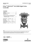
DVC2000 Digital Valve Controller
62.1:DVC2000
March 2014
D103167X012
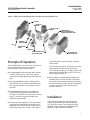
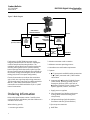
Figure 1. FIELDVUE DVC2000 Digital Valve Controller Assembly (Exploded View)
HOUSING
MOUNTING
FRAME
SINGLE ACTING
RELAY
PRIMARY SHIELD
(FOR ELECTROMAGNETIC
INTERFERENCE PROTECTION)
TERMINAL /
SENSOR BOARD
VENT
INTERCONNECT
BOARD
I/P
CONVERTER
MAIN BOARD WITH LCD
AND PUSHBUTTONS
ENVIRONMENTAL
COVER WITH LENS
W8946
Principle of Operation
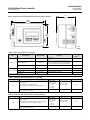
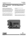
The DVC2000 (figures 1 and 2) receives a 4-20 mA set
point and position the valve by increasing or
decreasing the air output to an actuator.
n The input signal provides electrical power and the
set point simultaneously. The 4-20 mA signal is
routed into the terminals through a twisted pair of
wires.
n The unit's mainboard contains a microprocessor
that continuously runs a digital control algorithm.
This algorithm produces a “drive signal” to the I/P
converter.
relay output pressure to the actuator causes the
valve to move.
There are two relay options. The low pressure relay
operates with actuators that require less than
3.5 bar (50 psi) of supply air. The high pressure relay
operates with actuators that require 3.5 to 7.0 bar
(50 to 100 psi) of supply air.
n Valve position is sensed through the linkage-less
feedback system. The travel sensor is electrically
connected to the printed wiring board to provide a
travel feedback signal used in the control algorithm.
The valve continues to move until the correct
position is attained.
n The I/P converter assembly (or pre-amplifier) is
connected to supply pressure and converts the
electronic “drive signal” into a pneumatic “pressure
signal.” This pressure signal is the input to the
pneumatic relay assembly.
n The relay (or power amplifier) is also connected to
supply pressure and amplifies the small pressure
signal from the I/P converter into a larger pressure
output signal used by the actuator. The change in
Installation
The DVC2000 is designed for mounting on any
single acting pneumatic actuator up to 606 mm
(23-7/8 inches) of travel. The envelope and travel
feedback system conforms to VDI/VDE 3845, IEC
60534-6-1, and IEC 60534-6-2 standards.
5