1
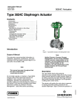
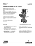
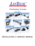
Product Bulletin 3024C Actuator 61.1:3024C March 2012 D103051X012 Fisherr 3024C Diaphragm Actuator The 3024C actuator is a compact spring opposed pneumatic diaphragm actuator incorporating a cast yoke mounting and is suitable for general purpose actuation of globe valves. It will position the valve plug in response to varying controller or valve positioner pneumatic output signals applied to the actuator diaphragm. The 3024C actuator can be assembled as either direct-acting or reverse-acting and provides dependable and on-off or throttling operation of automatic control valves. Features Application Versatility–With eight different configurations available, there is an actuator size to meet your needs. Multi-spring combinations allow for accurate selection of actuator thrust and valve travel. Reversible Action–The simple design allows the change of action from direct to reverse acting without the requirement for extra parts. Change of action can be easily made in the field. High Thrust Capability–The moulded diaphragm and high strength casings allow for a maximum casing pressure of 6 bar, enabling a high stem thrust for a given size diaphragm. Positive Connections–Split block stem connection provides a solid transfer of motion while allowing easy mounting and no linkages that create lost motion or inaccurate valve positioning. www.Fisher.com W8488 3024C Actuator Mounted on Fisher Valve Rugged Construction–The cast steel yoke and heavy duty steel casings provide stability, protection against corrosion, longevity, and resistance against misuse. Severe Temperature Applications–Through careful selection of construction materials, this actuator can be used for a wide range of ambient temperature conditions from a minimum of -40_C to a maximum of +82_C. Compact Design–The compact size minimizes weight and space needed. Available Configurations Refer to figure 1. Product Bulletin 3024C Actuator 61.1:3024C March 2012 D103051X012 Direct Action With the direct action mode on the 3024C actuator, applying air pressure to the upper side of the diaphragm forces the actuator stem downward while, at the same time, compressing the springs on the underside of the diaphragm. Refer to figure 1. When this pressure is reduced, the opposing spring force moves the actuator stem upwards. Should the loading pressure fail, the springs force the stem to the extreme upward position, thereby providing fail-open action for a push-down-to-close valve. Reverse Action With the reverse action mode, air is applied on the underside of the diaphragm while opposing spring force is on the top side. Increasing air pressure will force the stem upwards. When the loading pressure is reduced, the stem moves downwards. Should loading pressure fail, the springs force the stem to the extreme downward position, thereby providing fail-closed action for a push-down-to-close valve. Accessories Handwheels An optional side-mounted handwheel can be fitted to all sizes of actuator with travel up to 32 mm (1.25 inch) and where the maximum actuator thrust is less than 14,000 N (3150 lbf). These handwheels provide a robust method of manually operating the valve in an emergency or when there is a loss of instrument air. Refer to figures 2 and 3 and table 1 for details. Note, a side-mounted handwheel cannot be fitted on the sizes 45 and 45E actuator if an adjustable travel stop is fitted as well. When mounted on a direct action actuator, turning the handwheel clockwise always moves the stem downwards. When mounted on a reverse action actuator, turning the handwheel clockwise moves the stem upwards. Disengagement of the handwheel to enable automatic operation is simply accomplished by rewinding the handwheel. Valve Compatibility Adjustable Travel Stops With the availability of both metric and imperial threaded stem connectors, the 3024C can be used with a range of valve body assemblies such as the Fisher metric 1018S construction or imperial easy-et and RSS valve body constructions, along with others. Top mounted adjustable up travel stops are available for all actuators from size 30 to 40E. For the larger sizes 45 and 45E, an adjustable stop can be fitted to the actuator stem below the diaphragm casings. Both constructions give total variable adjustment of the travel of the actuator by limiting movement in the upward direction. Refer to figures 4 and 5. Table 1. Handwheel Specifications ACTUATOR SIZE mm Inch TURNS PER HANDWHEEL RIM FORCE mm/INCH OUTPUT (1, 2) TRAVEL FORCE mm Inch N lbs N lbs HANDWHEEL DIAMETER 30 and 30E 200 7.87 0.24 6.1 179 40 5000 34, 34E, 40, and 40E 1125 250 9.84 0.21 5.4 286 64 10000 2250 45 and 45E 250 9.84 0.21 5.5 400 90 14000 3150 1. Tangential handwheel force required to produce the handwheel output force shown. 2. Brass operating nut and stainless steel screw. Others Accessories such as transducers, positioners, position transmitters, air relays, volume boosters, switching valves, lockup valves, limit switches, and solenoid valves are also available for actuator mounting. They are described in separate publications. Contact your Emerson Process Management sales office for details. Contents Features . . . . . . . . . . . . . . . . . . . . . . . . . . . . . . . . . . . . . Available Configurations . . . . . . . . . . . . . . . . . . . . . . . Direct Action . . . . . . . . . . . . . . . . . . . . . . . . . . . . . . . . Reverse Action . . . . . . . . . . . . . . . . . . . . . . . . . . . . . . Valve Compatibility . . . . . . . . . . . . . . . . . . . . . . . . . . Accessories . . . . . . . . . . . . . . . . . . . . . . . . . . . . . . . . . . Handwheels . . . . . . . . . . . . . . . . . . . . . . . . . . . . . . . . 2 1 1 2 2 2 2 2 Adjustable Travel Stops . . . . . . . . . . . . . . . . . . . . . . . Others . . . . . . . . . . . . . . . . . . . . . . . . . . . . . . . . . . . . . Construction Materials . . . . . . . . . . . . . . . . . . . . . . . . . General Specifications . . . . . . . . . . . . . . . . . . . . . . . . . Actuator Dimensions . . . . . . . . . . . . . . . . . . . . . . . . . . Ordering Information . . . . . . . . . . . . . . . . . . . . . . . . . . 2 2 6 6 9 9 Product Bulletin 3024C Actuator 61.1:3024C March 2012 D103051X012 Figure 1. Typical Applications W8466-1 W8495-1 3024C (AIR RETRACTS STEM) 3024C (AIR EXTENDS STEM) W8496-1 3024C FITTED WITH A SIDE-MOUNTED HANDWHEEL 3 Product Bulletin 61.1:3024C March 2012 Figure 2. Side-Mounted Handwheel with Air-Extends-Stem Actuator 1Q57490 Figure 3. Side-Mounted Handwheel with Air-Retracts-Stem Actuator 1Q57490 4 3024C Actuator D103051X012 3024C Actuator D103051X012 Product Bulletin 61.1:3024C March 2012 Figure 4. Up Stop for Actuator Sizes up to 40 and 40E 3Q57478 Figure 5. Up Stop for Actuator Sizes 45 and 45E 3Q57478 5 Product Bulletin 3024C Actuator 61.1:3024C March 2012 D103051X012 Construction Materials General Specifications Refer to figure 1. The sizes 30, 34, 40 and 45 are typically used with the 1018S valve bodies. The sizes 30E, 34E, 40E and 45E are used with such valves as the easy-e or RSS. Diaphragm Casings: Steel Diaphragm: Nitrile Diaphragm Plate: Aluminium Table 2. Volumetric Data (Air-to-Open and Air-to-Close) Springs: Steel Spring locator: Steel Actuator Stem: Stainless steel O-Rings: Nitrile ACTUATOR SIZE ACTUATOR TRAVEL 30 16 mm 30E 0.75 inch 34 16 mm 34E 0.75 inch 40 Yoke: Cast steel 40E Stem Connector: Steel 45 Nameplate: Stainless steel 45E VOLUME (L) 0% Travel 100% Travel 0.6 0.9 1.9 2.6 32 mm 1.5 2.8 1.125 inch 1.5 2.8 1.5 inch 1.8 3.3 2 inch 1.5 3.5 32 mm 3.0 5.7 1.125 inch 3.0 5.7 1.5 inch 3.8 7.0 2 inch 3.0 7.4 Travel Indicator Scale: Stainless steel Table 3. Specifications Actuator Size Specification 30 30E 34 Nominal Effective Area Maximum Operating Pressure to Diaphragm Maximum Travel Yoke Boss Diameter Valve Stem Connector Thread Temperature Range 6 34E 40 40E 45 45E --- See tables 4 and 5 Bar 6 psig 87 mm 16 --- 16 --- 32 --- 32 Inch --- 0.75 --- 0.75 --- 2 --- 2 mm 54 mm 54 mm 54 mm 54 mm 71 mm 71 mm 71 mm 71mm Inch 2-1/8 2-1/8 2-1/8 2-1/8 2-13/16 2-13/16 2-13/16 2-13/16 mm M12 x 1.75 --- M12 x 1.75 --- M16 x 2 --- M16 x 2 --- Inch --- 3/8-24 --- 3/8-24 --- 1/2-20 --- 1/2-20 _C Nitrile diaphragm and steel studs and nuts: -40 to +82 _F Nitrile diaphragm and steel studs and nuts: -40 to + 180 Pressure Connections Inch Maximum Approximate Weight (without handwheel) kg 9.5 9.5 18.0 18.0 1/4 — 18 NPT 19.5 21.5 33.5 35.5 lb 20.9 20.9 39.7 39.7 43.0 47.4 73.9 78.3 Maximum Approximate Weight (with handwheel) kg 16.5 16.5 25.0 25.0 26.5 28.5 40.5 42.5 lb 36.4 36.4 55.1 55.1 58.4 62.8 89.3 93.7 Product Bulletin 3024C Actuator 61.1:3024C March 2012 D103051X012 Table 4. Additional Specifications (Action - Air Extends Stem) TRAVEL SPRING RANGE SIZE SPRING SET/QTY mm Inch 30 217/3 218/5 218/7 16 --- 30E 217/3 218/5 218/7 --- 0.75 219/3 212/5 212/7 16 --- 34E 219/3 212/5 212/7 --- 0.75 40 212/3 213/6 214/7 34 40E 45 45E 32 --- 212/3 213/6 214/7 --- 1.125 213/4 214/5 214/7 --- 1.5 213/4 214/5 214/7 --- 2 221/8 221/12 223/12 32 --- 221/8 221/12 223/12 --- 1.125 221/8 221/12 223/12 --- 1.5 221/8 221/12 223/12 --- 2 Bar 0.3 - 1.1 1.3 - 2.0 1.8 - 2.9 0.3 - 1.3 1.3 - 2.2 1.8 - 3.0 0.3 - 1.1 0.9 - 1.7 1.3 - 2.3 0.3 - 1.3 0.9 - 1.8 1.3 - 2.5 0.4 - 1.3 0.8 - 1.8 1.2 - 2.4 0.4 - 1.2 0.8 - 1.7 1.2 - 2.3 0.3 - 1.0 0.6 - 1.5 0.9 - 2.1 0.2 - 1.2 0.5 - 1.7 0.7 - 2.4 0.8 - 1.6 1.2 - 2.5 1.5 - 3.1 0.8 - 1.6 1.2 - 2.3 1.5 - 3.0 0.5 - 1.4 0.8 - 2.2 1.0 - 2.7 0.5 - 1.7 0.7 - 2.5 0.9 - 3.1 Psig 4 - 16 19 - 29 26 - 42 4 - 19 19 - 32 26 - 44 4 - 16 13 - 25 19 - 33 4 - 19 13 - 26 19 - 36 6 - 19 12 - 26 17 - 35 6 - 17 12 - 25 17 - 33 4 - 15 9 - 22 13 - 30 3 - 17 7 - 25 10 - 35 12 - 23 17 - 36 22 - 45 12 - 23 17 - 33 22 - 44 7 - 20 12 - 32 15 - 39 7 - 25 10 - 36 12 - 45 EFFECTIVE DIAPHRAGM AREA (1) cm2 160 160 160 160 160 160 400 400 400 400 400 400 390 390 390 390 390 390 380 380 380 370 370 370 790 790 790 790 790 790 780 780 780 770 770 770 Inches2 24.8 24.8 24.8 24.8 24.8 24.8 62.0 62.0 62.0 62.0 62.0 62.0 60.5 60.5 60.5 60.5 60.5 60.5 58.9 58.9 58.9 57.4 57.4 57.4 122 122 122 122 122 122 121 121 121 119 119 119 MAXIMUM OUTPUT THRUST (MAXIMUM ACTUATOR STEM FORCE)(2) N Lb 7840 1760 6400 1440 4960 1120 7520 1690 6080 1360 4800 1070 19,600 4400 17,200 3840 14,800 3350 18,800 4220 16,800 3780 14,000 3160 18,300 4110 16,400 3690 14,000 3150 18,700 4230 16,800 3750 14,400 3270 19,000 4240 17,100 3830 14,800 3360 17,800 4220 15,900 3560 13,300 2980 34,800 7810 27,600 6220 22,900 5120 34,800 7810 29,200 6590 23,700 5250 35,900 8110 29,600 6650 25,700 5810 33,100 7380 26,900 6070 22,300 5000 1. Effective diaphragm area at 0% valve travel from seat. 2. Based upon 6 bar operating pressure to the diaphragm and valve travel at 0% from seat. This does not consider limitation to the valve such as stem buckling load. Consult your Emerson Process Management sales office for details. 7 Product Bulletin 3024C Actuator 61.1:3024C March 2012 D103051X012 Table 5. Additional Specifications (Action - Air Retracts Stem) TRAVEL SPRING RANGE SIZE SPRING SET/QTY mm Inch 30 217/3 218/5 218/7 16 --- 30E 217/3 218/5 218/7 --- 0.75 34 219/3 212/5 212/7 16 --- 34E 219/3 212/5 212/7 --- 0.75 40 212/3 213/6 214/7 32 --- 212/3 213/6 214/7 --- 1.125 213/4 214/5 214/7 --- 1.5 213/4 214/5 214/7 --- 2 221/8 221/12 223/12 32 --- 221/8 221/12 223/12 --- 1.125 221/8 221/12 223/12 --- 1.5 221/8 221/12 223/12 --- 2 40E 45 45E Bar 0.5 - 1.3 1.4 - 2.2 2.0 - 3.1 0.3 - 1.3 1.2 - 2.2 1.8 - 3.1 0.6 - 1.4 1.1 - 1.9 1.6 - 2.7 0.4 - 1.4 1.0 - 1.9 1.4 - 2.7 0.4 - 1.3 0.8 - 1.8 1.2 - 2.4 0.5 - 1.3 0.9 - 1.8 1.3 - 2.4 0.4 - 1.1 0.7 - 1.6 1.0 - 2.3 0.2 - 1.2 0.5 - 1.8 0.8 - 2.5 0.8 - 1.7 1.2 - 2.5 1.6 - 3.2 0.9 - 1.7 1.4 - 2.5 1.7 - 3.2 0.7 - 1.6 1.1 - 2.4 1.3 - 3.1 0.5 - 1.7 0.8 - 2.6 0.9 - 3.2 Psig 7 - 19 20 - 32 29 - 45 4 - 19 17 - 32 26 - 45 9 - 20 16 - 28 23 - 39 6 - 20 15 - 28 20 - 39 6 - 19 12 - 26 17 - 35 7 - 19 13 - 26 19 - 35 6 - 16 10 - 23 15 - 33 3 - 17 7 - 26 12 - 36 12 - 25 17 - 36 23 - 46 13 - 25 20 - 36 25 - 46 10 - 23 16 - 35 19 - 45 7 - 25 12 - 38 13 - 46 EFFECTIVE DIAPHRAGM AREA(1) cm2 170 170 170 175 175 175 410 410 410 420 420 420 450 450 450 440 440 440 410 410 410 440 440 440 940 940 940 910 910 910 870 870 870 940 940 940 Inches2 26.4 26.4 26.4 27.1 27.1 27.1 63.6 63.6 63.6 65.1 65.1 65.1 69.8 69.8 69.8 68.2 68.2 68.2 63.6 63.6 63.6 68.2 68.2 68.2 146 146 146 141 141 141 135 135 135 146 146 146 MAXIMU M OUTPUT THRUST (MAXIMUM ACTUATOR STEM FORCE)(2) N Lb 780 170 2360 530 3360 760 550 120 2180 490 3110 700 2450 550 4610 1040 6560 1480 1880 420 4120 930 5870 1320 1880 420 3640 820 5530 1240 2200 500 3970 890 5920 1330 1560 350 3010 680 4270 960 1060 240 2390 540 3400 760 7790 1750 11,700 2630 14,700 3300 8350 1880 12,500 2810 15,700 3530 6150 1380 9230 2080 11,500 2590 4740 1070 7110 1600 8800 1980 1. Effective diaphragm area at 0% valve travel from seat. 2. Based on zero operating pressure to the diaphragm and valve travel at 0% from valve seat. This does not consider limitations such as stem buckling load. Consult your Emerson Process Management sales office for details. 8 Product Bulletin 3024C Actuator 61.1:3024C March 2012 D103051X012 Actuator Dimensions See table 6. Table 6. Dimensions(1) ACTUATOR SIZE 30 34 40 45 VALVE TRAVEL 16 mm 16 mm 32 mm 32 mm 30E 34E 40E 40E 40E 45E 45E 45E 0.75 0.75 1.125 1.5 2 1.125 1.5 2 YOKE BOSS, INCHES C 2-1/8 (54 mm) 2-1/8 (54 mm) 2-13/16 (71 mm) 2-13/16 (71 mm) 215 315 315 420 2-1/8 2-1/8 2-13/16 2-13/16 2-13/16 2-13/16 2-13/16 2-13/16 8.5 12.4 12.4 12.4 12.4 16.5 16.5 16.5 E 370 400 420 450 Inches 14.6 15.8 17.9 18.9 18.9 19.3 20.1 20.1 F(2) AR 140 140 170 170 105 105 133 133 5.6 5.6 8.1 8.3 8.5 8.1 8.3 8.5 4.7 4.7 6.6 6.6 6.2 6.6 6.6 6.2 Js Millimeters 205 250 250 250 8.1 9.8 9.8 9.8 9.8 9.8 9.8 9.8 Hs M (ARS)(3) M (AES)(4) 280 280 280 280 185 185 210 210 80 80 100 100 11.0 11.0 11.0 ----11.0 ----- 7.3 7.3 9.6 ----9.6 ----- 3.1 3.1 5.5 ----5.5 ----- 1. See figures 6 and 7. 2. This is the centre of the stem connector at the fully-up postion. This ensures the positioner feedback arm, if fitted, is horizontal at mid-travel. 3. ARS - air retracts stem. 4. AES - air extends stem. Ordering Information 7. Stroking time requirements, if critical When ordering please specify the following information: 8. Ambient temperature range Application Details: 1. On-off or throttling service 2. Input signal range 3. Maximum supply pressure 4. Valve body type and size with which the actuator will be used Actuator and Positioner Be sure to specify the actuator type number required, whether a positioner is needed, whether a handwheel is required and whether an adjustable travel stop is required. Refer to the Specifications section in this bulletin. Review the information under each specification and in the referenced tables and figures. Specify the desired choice wherever there is a selection to be made. 5. Valve plug travel Valve Body and Accessories 6. Actuator thrust required with the actuator stem both fully retracted and fully extended Refer to the separate valve body bulletin and bulletins covering accessories for ordering information. 9 Product Bulletin 3024C Actuator 61.1:3024C March 2012 D103051X012 Figure 6. Actuator Dimensions with Handwheel (see table 6) JS M HS REVERSE-ACTING JS M 1Q57490 HS DIRECT-ACTING 10 Product Bulletin 3024C Actuator 61.1:3024C March 2012 D103051X012 Figure 7. Actuator Dimensions (see table 6) AR (ACTUATOR REMOVAL) C E F D 1Q57491 11 Product Bulletin 61.1:3024C March 2012 3024C Actuator D103051X012 Neither Emerson, Emerson Process Management, nor any of their affiliated entities assumes responsibility for the selection, use or maintenance of any product. Responsibility for proper selection, use, and maintenance of any product remains solely with the purchaser and end user. Fisher and easy-e are marks owned by one of the companies in the Emerson Process Management business unit of Emerson Electric Co. Emerson Process Management, Emerson, and the Emerson logo are trademarks and service marks of Emerson Electric Co. All other marks are the property of their respective owners. The contents of this publication are presented for informational purposes only, and while every effort has been made to ensure their accuracy, they are not to be construed as warranties or guarantees, express or implied, regarding the products or services described herein or their use or applicability. All sales are governed by our terms and conditions, which are available upon request. We reserve the right to modify or improve the designs or specifications of such products at any time without notice. Emerson Process Management Marshalltown, Iowa 50158 USA Sorocaba, 18087 Brazil Chatham, Kent ME4 4QZ UK Dubai, United Arab Emirates Singapore 128461 Singapore www.Fisher.com E 122003, 2012 Fisher Controls International LLC. All rights reserved.