1
MOUNTING AND WIRING
4
CONTINUED FROM SECOND PAGE
THERMOSTAT
C‡
B
O
Y
G
W
RC
RH
SYSTEM
JUMPER
WIRE
Cooling
System
THERMOSTAT
C‡
B
Y
O
G
W
RC
Fan
Relay
Hot
Heating
System
24 VAC
Neutral
RH
SYSTEM
Fan
Relay
Heating
System
HEATING
TRANSFORMER
Hot
Hot
24 VAC
NOTE
24 VAC
120 VAC
COOLING TRANSFORMER
TRANSFORMER
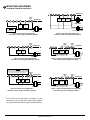
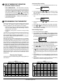
Figure 5. Typical wiring diagram for
heat/cool, 5-wire, two-transformer systems
Figure 2. Typical wiring diagram for
heat only, 3-wire, single transformer systems
JUMPER
WIRE
C‡
JUMPER
WIRE
THERMOSTAT
B
O
Y
G
W
RC
RH
SYSTEM
Cooling
System
Fan
Relay
JUMPER
WIRE
THERMOSTAT
C‡
B
Y
O
G
W
RC
Reversing Compressor Fan
Valve*
Contactor Relay
Hot
24 VAC
120 VAC
Neutral
* Reversing valve is energized when the
system switch is in the COOL position
TRANSFORMER
Figure 3. Typical wiring diagram for
cool only, 3-wire, single transformer systems
RH
SYSTEM
Hot
24 VAC
120 VAC
Neutral
Neutral
For 2-wire Heat only,
attach to RH and W
120 VAC
120 VAC
Neutral
TRANSFORMER
Figure 6. Typical wiring diagram for heat pump
with reversing valve energized in COOL
NOTE
RED jumper wire (provided with thermostat) must be
connected between thermostat RH and RC terminals
for proper thermostat operation with this system.
C‡
JUMPER
WIRE
O
Y
G
W
RC
RH
SYSTEM
Cooling
System
Fan
Relay
JUMPER
WIRE
THERMOSTAT
C‡
B
O
Y
G
W
RC
RH
SYSTEM
Heating
System
Reversing Compressor Fan
Valve*
Contactor Relay
Hot
24 VAC
120 VAC
Neutral
TRANSFORMER
Hot
24 VAC
* Reversing valve is energized when the
system switch is in the HEAT position
120 VAC
Neutral
TRANSFORMER
Figure 7. Typical wiring diagram for heat pump
with reversing valve energized in HEAT
Figure 4. Typical wiring diagram for
heat/cool, 4-wire, single transformer systems
‡
JUMPER
WIRE
THERMOSTAT
B
The 24 Volt neutral connection to terminal C on the
thermostat is not required if the batteries are replaced
once a year with fresh “AA” Energizer® alkaline batteries.
www.white-rodgers.com