1
Bulletin 71.1:627W
Specifications
Available Constructions
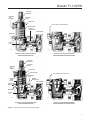
Type 627W: Direct-operated pressure reducing
liquid regulator (Figure 2).
Type 627WH: Type 627W with a diaphragm limiter to deliver a higher outlet pressure (Figure 2).
Control Line Option: Type 627W or 627WH
with a stem seal between the body outlet pressure
and diaphragm case. Pressure is measured under
the diaphragm through the 1/4 NPT downstream control line connection (Figure 2).
Body Sizes and End Connection Styles
NPT: 3/4, 1, or 2
CL150, CL300, or CL600 RF Flanged: NPS 1 or 2 (DN 25 or 50)
PN 16, 25, or 40: NPS 1 or 2 (DN 25 or 50)
Maximum Operating Inlet And Outlet Pressure Ranges(1)
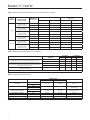
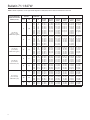
See Table 1 for pressures by orifice and spring range
Body Pressure Shell Rating(1)
NPT (Steel): 2000 psig (138 bar)
NPT (Ductile Iron): 1000 psig (69,0 bar) CL600 RF Flanged (Steel): 1500 psig (103 bar)
Maximum Spring And Diaphragm Casing Pressure(1)
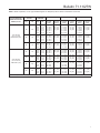
See Table 2
Construction Materials
Body: Ductile iron, stainless steel, or steel
Spring Case: Stainless steel, steel, or ductile iron
Diaphragm Case: Ductile iron, stainless steel,
or steel
O-Rings: Nitrile (NBR), Fluorocarbon (FKM),
Ethylenepropylene (EPDM), or elastomeric
Polytetrafluoroethylene (PTFE)
Diaphragm: Nitrile (NBR), Fluorocarbon (FKM),
Ethylenepropylene (EPDM), or PTFE protector
Lever, Lever support, Orifice, and Stem guide:
   Stainless steel
Disk Holder with Valve Disk
Stainless steel with; Nylon (PA), Nitrile (NBR),
Fluorocarbon (FKM), or Ethylenepropylene (EPDM)
Temperature Capabilities(1)
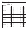
See Table 3
Pressure Registration
Type 627W or 627WH: Internal
Optional: External through 1/4 NPT control line
connection in the diaphragm case
Spring Case Vent Connection
3/4 NPT with removable screened vent assembly
Orifice Sizes
1/4 or 1/2-inch (6,3 or 13 mm)
Approximate Weight
With Ductile Iron or Steel Casings:
10 pounds (5 kg)
Regulator Capacities
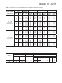
Type 627W: See Table 4
Type 627WH: See Table 5
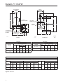
External Dimensions
See Figure 4
Cv Coefficients at 20% Proportional Band (Droop)
Type 627W: See Table 6
Type 627WH: See Table 7
Flow and Sizing Coefficients
See Table 8
Option
Outlet Pressure Gauge (Brass):
0 to 30 psi (0 to 2,1 bar); 0 to 60 psi (0 to 4,1 bar);
0 to 160 psi (0 to 11,0 bar); 0 to 300 psi (0 to 20,7 bar); or 0 to 600 psi (0 to 41,4 bar)
1. The pressure/temperature limits in this Bulletin and any applicable standard or code limitation should not be exceeded.
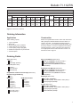
Installation
Type 627W regulators may be installed in any position, as long
as flow will be in the same direction as that indicated by the
body arrow. The pressure and temperature limitations in the
Specifications table must be observed and the downstream
equipment protected from being overpressured.
Liquid pressure control systems should be designed using good
engineering practices to eliminate quick starting or stopping
of the flow stream, which can produce water hammer. The
regulator should be installed so that the screened spring case
vent is protected from anything that might clog it. To obtain the
published capacities, the inlet and outlet piping should be the
same as the regulator size.
A downstream control line is field installed with the control line
version of the Type 627W or the Type 627WH.
2
Fisher® provides an instruction manual with every regulator
shipped. Refer to this for complete installation, operation, and
maintenance instructions. Included is a complete listing of
individual parts and recommended spare parts.
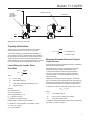
Monitor Installation
One regulator (worker) is set at the desired downstream
pressure. The other regulator (monitor) is set at a higher
pressure and remains wide open. If the worker regulator fails
open, the monitor regulator controls the downstream pressure
at its setpoint. System lock-up pressure will be the monitor
lock-up pressure (see Figure 3).