1
SSURE
E
SSURE
SSURE
ED PRESSURE
ESSURE
E
Bulletin 71.7:167D
ADJUSTING SCREW
ADJUSTING SCREW
CONTROL SPRING
DIAPHRAGM
CONTROL SPRING
O-RING
SOFT SEAT
DIAPHRAGM
O-RING
PORT C
PORT A
VALVE STEM
BODY
PORT A
PORT C
VALVE PLUG
ORIFICE SEAT
VALVE SPRING
VALVE STEM
BODY
VALVE PLUG
ORIFICE SEAT
M1152
VALVE SPRING
M1151
PORT B
INLET PRESSURE
TYPE 167D TWO-WAY
SWITCHING
VALVE
TYPE
167DA
THREE-WAY SWITCHING VALVE
OUTLET
PRESSURE
(WHEN LOADING PRESSURE IS LESS
THAN
SETPOINT)
OUTLET PRESSURE (WHEN LOADING PRESSURE IS EQUAL TO OR GREATER THAN SETPOINT)
ATMOSPHERIC PRESSURE
INLET
PRESSURE
INLET
PRESSURE LOADING
PRESSURE
OUTLET
PRESSURE
(WHEN
LOADING LOADING
PRESSURE ISPRESSURE
LESS THAN SETPOINT)
OUTLET PRESSURE (WHEN
IS LESS THAN SETPOINT)
OUTLET
PRESSURE
(WHEN (WHEN
LOADING LOADING
PRESSURE ISPRESSURE
EQUAL TO OR IS
GREATER
THAN
OUTLET
PRESSURE
EQUAL
TOSETPOINT)
OR GREATER THAN SETPOINT)
ATMOSPHERIC
PRESSURE
ATMOSPHERIC
PRESSURE
LOADING
PRESSURE
LOADING
PRESSURE
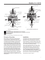
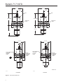
Figure 2. 167D Series Operational Schematics (Port D not shown)
Principle of Operation
Installation
Refer to Figure 2 and also refer to Figures 3 through
5 for port D location. Control pressure enters the
switching valves through Port D (not shown in Figure 2)
and registers under the diaphragm. Control pressure
overcomes the spring force and the diaphragm, and
raises the valve plug, closing port C and opening port
B of the Type 167DA three-way switching valve. In this
condition, the Type 167D construction is turned off and
the Type 167DA construction provides flow from path A
to B. If, either intentionally or through pneumatic failure,
the control pressure drops below the spring force, the
diaphragm and valve plug move downward, opening
port C and closing port B of the Type 167DA three-way
switching valve. In this condition both constructions
provide a flow path from port A to port C. The pressure
change necessary to switch the valve depends on the
spring used and the setting of the adjusting screw on the
switching valve.
The switching valve can be mounted in any position,
providing the vent in the spring case is free from
obstruction. Connect the pneumatic control line to
the port marked “D” on the valve body. Ports A and C
(and B on the Types 167DA and 167DAS valve) are
connected for the desired switching valve response to
loss or decrease in pneumatic pressure.
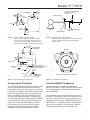
Figure 5 shows typical application of the Types 167DA
and 167DAS switching valve. If the control valve inlet
pressure falls below a predetermined setting, the onoff controller turns off control pressure to the switching
valve. This causes the switching valve to bleed the
control valve diaphragm pressure to atmosphere, closing
the control valve. The control valve remains closed until
the inlet pressure is restored to the desired setting.
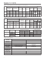
Dimensions are shown in Figure 7.
3