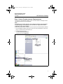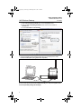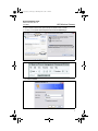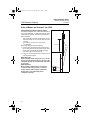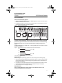
1
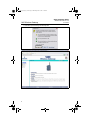
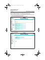
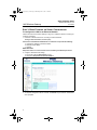
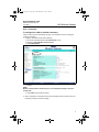
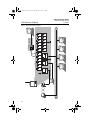
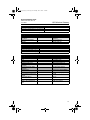
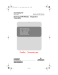
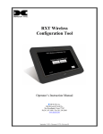
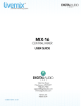
1420_QIG_Rev_CA.fm Page 1 Thursday, June 7, 2007 1:18 PM
Quick Installation Guide
00825-0100-4420, Rev CA
June 2007
1420 Wireless Gateway
1420 Wireless Gateway
Start
Step 1: Initial Connection for Configuration
Step 2: Basic Security and Time Configuration
Step 3: Basic Ethernet or Serial Configuration
Step 4: Mount and Connect the 1420
End
¢00825-0100-4420[¤
1420_QIG_Rev_CA.fm Page 2 Thursday, June 7, 2007 1:18 PM
Quick Installation Guide
00825-0100-4420, Rev CA
June 2007
1420 Wireless Gateway
© 2007 Rosemount Inc. All rights reserved. All marks property of owner.
Emerson Process Management Rosemount Temperature GmbH Emerson Process Management
Frankenstrasse 21
Rosemount Division
Asia Pacific Private Limited
8200 Market Boulevard
Chanhassen, MN USA 55317
T (US) (800) 999-9307
T (Intnl) (952) 906-8888
F (952) 949-7001
63791 Karlstein
Germany
T 49 (6188) 992 0
F 49 (6188) 992 112
1 Pandan Crescent
Singapore 128461
T (65) 6777 8211
F (65) 6777 0947 / (65) 6777 0743
[email protected]
IMPORTANT NOTICE
This installation guide provides basic guidelines for the 1420 Wireless Gateway. It does
not provide instructions for detailed configuration, diagnostics, maintenance, service,
troubleshooting, or installations. Refer to the 1420 Wireless Gateway reference manual
(document number 00809-0100-4420) for more instruction. The manual and this QIG are
also available electronically on www.rosemount.com.
WARNING
Explosions could result in death or serious injury:
Installation of this device in an explosive environment must be in accordance with the
appropriate local, national, and international standards, codes, and practices. Please
review the Hazardous Locations Certifications for any restrictions associated with a safe
installation.
Electrical shock can result in death or serious injury
• Avoid contact with the leads and terminals. High voltage that may be present on leads
can cause electrical shock.
WARNING
Explosion Hazard
Do not disconnect equipment when a flammable or combustible atmosphere is present.
IMPORTANT NOTICE
The 1420 Wireless Gateway should be installed before installing any other wireless
devices. This will result in a simpler and faster network installation.
Physical Device Revision 1.0
Web Server Revision 3.0.8
Network Revision 1.0
2
1420_QIG_Rev_CA.fm Page 3 Thursday, June 7, 2007 1:18 PM
Quick Installation Guide
00825-0100-4420, Rev CA
June 2007
1420 Wireless Gateway
STEP 1: INITIAL CONNECTION FOR CONFIGURATION
To configure the 1420 Wireless Gateway, a local connection between a PC/laptop and the
1420 Wireless Gateway must be established.
NOTE:
If a PC/laptop from another network is used, carefully record the current IP address
and other settings so the PC/laptop can be returned to its original network when
configuration of the 1420 is finished.
Perform the following steps to establish a local connection with the 1420 Wireless Gateway:
1. On the PC/laptop, install the Java Plug-in found on the CD provided with the 1420. The
Plug-in can also be found at http://java.com/
2. Under Network Connections:
a. Select Local Area Connection
b. Right click to select Properties.
3
1420_QIG_Rev_CA.fm Page 4 Thursday, June 7, 2007 1:18 PM
Quick Installation Guide
1420 Wireless Gateway
00825-0100-4420, Rev CA
June 2007
c. Select Internet Protocol (TCP/IP), then click the Properties button
d. Select the Use the following IP address button and set the IP address to
192.168.1.12
e. Set the Subnet Mask to 255.255.255.0
f. Select OK for each of the settings windows that have opened.
3. Using the supplied crossover Ethernet cable, attach your PC/laptop to the 1420’s
P1 Ethernet Receptacle (far right Ethernet receptacle).
PC/Laptop
P1 Ethernet
Receptacle
24 V DC
Power Input
+
-
Modbus
S
S
A
Not Used
B
+
Not Used
-
S
S
-
S
S
-
+
-
+
Case
+
POE
P2
P1
Not Used
Not Used
(Covered)
Crossover Cable
WARNING
Do not connect to the P3 Power Over Ethernet (POE) port. This port supplies power
and could potentially damage the PC/laptop.
4
1420_QIG_Rev_CA.fm Page 5 Thursday, June 7, 2007 1:18 PM
Quick Installation Guide
00825-0100-4420, Rev CA
June 2007
1420 Wireless Gateway
4. Open a standard web browser (Internet Explorer, Mozilla Firefox or similar).
5. Uncheck proxies (Tools>Internet Options>Connections>LAN Settings)
6. Access the 1420’s default web page at https://192.168.1.10
a. Log on as User: admin
b. Password: default
5
1420_QIG_Rev_CA.fm Page 6 Thursday, June 7, 2007 1:18 PM
Quick Installation Guide
1420 Wireless Gateway
c. Click Yes to proceed through the Security Alert
The 1420 Home Page will appear as shown below
6
00825-0100-4420, Rev CA
June 2007
1420_QIG_Rev_CA.fm Page 7 Thursday, June 7, 2007 1:18 PM
Quick Installation Guide
00825-0100-4420, Rev CA
June 2007
1420 Wireless Gateway
STEP 2: BASIC SECURITY AND TIME CONFIGURATION
To configure the basic security of the 1420 Wireless Gateway, perform the following steps.
1. Navigate to Setup>Security>User Accounts
2. Set and confirm new passwords for each of the access levels
3. Click Submit
4. Navigate to Setup>Time
5. Select method and click Submit
7
1420_QIG_Rev_CA.fm Page 8 Thursday, June 7, 2007 1:18 PM
Quick Installation Guide
1420 Wireless Gateway
00825-0100-4420, Rev CA
June 2007
STEP 3: BASIC ETHERNET OR SERIAL CONFIGURATION
To configure the 1420 for an Ethernet Network:
Table 2: Ethernet Communication Settings on page 15 is available to assist in recording the
necessary information.
1. Determine 1420 Ethernet Port for connecting to Ethernet Network
If using a wired connection, use Port 1 (P1)
IT/Process Control Network Administrator or Technician can provide the following:
a. 1420 fixed IP Address or DHCP Host Name
b. Netmask (Subnet Mask)
c. Gateway
BEST PRACTICE:
Keep these values in a secure location not accessible by unauthorized personnel.
2. Configure 1420 Ethernet IP settings
a. Access the 1420 with Administrator access
b. Navigate to Setup>Internet Protocol>Address
c. Enter configuration information determined above
3. To complete configuration without a firewall, click Submit and proceed with 1420 Restart
when prompted.
8
1420_QIG_Rev_CA.fm Page 9 Thursday, June 7, 2007 1:18 PM
Quick Installation Guide
00825-0100-4420, Rev CA
June 2007
1420 Wireless Gateway
STEP 3 CONTINUED...
To configure the 1420 for a Serial connection:
Table 4: Serial Communication Settings on page 15 is available to assist in recording the
necessary information.
1. Configure 1420 Serial Communication Settings
a. Access the 1420 Web Interface with Administrator access
b. Navigate to Setup>Modbus>Communication
c. Click Enable Modbus
d. Configure the 1420 Modbus Communication settings to match the Host Modbus
settings
NOTE:
Modbus communications will fail if they are not configured identically on the Host
and the 1420.
e. Click Submit and proceed with restart
2. When configuration is completed, disconnect the PC/laptop from the 1420 and return the
PC/laptop to its previous network settings.
9
1420_QIG_Rev_CA.fm Page 10 Thursday, June 7, 2007 1:18 PM
Quick Installation Guide
1420 Wireless Gateway
00825-0100-4420, Rev CA
June 2007
STEP 4: MOUNT AND CONNECT THE 1420
Integral Antenna with the 1420 on a Mast
The optimal installation of the 1420 Wireless Gateway is
on a pole approximately 1.8 meters above the top of the
exterior wall of a building. The following hardware and
tools are needed:
• Pipe mount with holes spaced 3.06 inches (78 mm)
apart horizontally and 11.15 inches (283 mm) apart
vertically.
• Two 3.06 inch (78 mm) by 5/16 inch U-bolts
• 1/2 inch wrench
Mount the gateway by doing the following:
1. Insert one U-bolt around the pipe and through the
top mounting holes of the pipe mount and the 1420,
and another U-bolt through the bottom mounting
holes of the pipe mount and the 1420.
2. Using a 1/2 inch socket-head wrench, fasten the nuts
to the U-bolts and tighten.
BEST PRACTICE
When mounting outside, best practice is to run the
Serial or primary Ethernet cable (P1) directly to the
Information System. Use conduit and/or strain relief
as necessary.
BEST PRACTICE
When installing cable/conduit, run an ethernet
connection from 1420 port P2 to a convenient
location indoors (if the 1420 was ordered with
Output Code 2). This will simplify future
configuration changes.
10
1.8 m (6 ft.)
Strain
Relief
1420_QIG_Rev_CA.fm Page 11 Thursday, June 7, 2007 1:18 PM
Quick Installation Guide
00825-0100-4420, Rev CA
June 2007
1420 Wireless Gateway
STEP 4 CONTINUED...
Connect to Information System
1. Wire the 1420 Primary Ethernet output or Serial Output connection to the Host System
Ethernet or Serial input connections.
2. For Serial connections, connect A to A, B to B and make sure all terminations are clean
and secured to avoid wiring connection problems.
Figure 1. 1420 Terminal Block Diagram
Serial
Modbus
24 V DC
Power Input
+
-
S
A
B
Not Used
+
Not Used
-
S
S
-
S
S
-
+
-
+
Case
+
POE
(Covered)
P2
(Secondary)
P1
(Primary)
Not Used
Not Used
BEST PRACTICE
Typically, twisted shielded pair cable is used to wire the Serial connection. Standard
practice is to ground the shield on the Serial Host side and leave the shield floating
on the 1420 side. Be sure to insulate the 1420 shield to avoid grounding issues.
NOTE:
In most systems, A = Tx + and B = Rx -. In some systems, this is reversed. For 4-wire
systems, see Figure 2.
Figure 2. Typical Full Duplex (4-wire) to Half Duplex (2-wire) Conversion Diagram
Tx +
Tx + = (A)
Rx +
Tx Rx - = (B)
Rx Confirm wiring configuration with host system documentation.
Supply Power
After mounting is complete supply power to the 1420 according to the following steps:
1. Ground the 1420 using suitable grounding methods. There is a case ground lug located
near the terminal block, and an external ground lug located near the conduit entries on
the bottom of the housing.
2. Connect the 24 V DC power wiring to the Power Input terminals in the 1420. The 1420
requires 500 mA of current. (see Terminal and Integration Diagram on page 14)
3. Close the terminal cover and tighten securely.
BEST PRACTICE
Use an uninterruptible power supply (UPS) to ensure that the network is still
functional should there be a loss of power.
11
1420_QIG_Rev_CA.fm Page 12 Thursday, June 7, 2007 1:18 PM
Quick Installation Guide
1420 Wireless Gateway
00825-0100-4420, Rev CA
June 2007
PRODUCT CERTIFICATIONS
Approved Manufacturing Locations
Rosemount Inc. – Chanhassen, Minnesota, USA
Telecommunication Compliance
All wireless devices require certification to ensure that they adhere to regulations regarding
the use of the RF spectrum. Nearly every country requires this type of product certification.
Emerson is working with governmental agencies around the world to supply fully compliant
products and remove the risk of violating country directives or laws governing wireless
device usage. To see which countries our devices have received certification for use in, see
www.rosemount.com/smartwireless.
European Union Directive Information
The EC declaration of conformity for all applicable European directives for this product can
be found on the Rosemount website at www.rosemount.com. A hard copy may be obtained
by contacting your local sales representative.
ATEX Directive (94/9/EC)
Emerson Process Management complies with the ATEX Directive.
Electro Magnetic Compatibility (EMC) (2004/108/EC)
EN 61326-1: 1997 with amendments A1, A2, and A3– Industrial
Radio and Telecommunications Terminal Equipment Directive
(R&TTE)(1999/S/EC)
Emerson Process Management complies with the R&TTE Directive
FM Ordinary Locations Approval
The 1420 Wireless Gateway has been evaluated and approved by FM for ordinary
locations.
CE EMC Marking
Compliance with European Union EMC
Hazardous Location Certifications
North American Certifications
N5 FM Division 2
Certificate Number: See Certificate
Nonincendive for Class I, Division 2, Groups A,B,C, and D;
Dust Ignitionproof for Class II,III, Division 1,
Groups E,F, and G; Indoor/outdoor locations;
NEMA Type 4X
Temperature Code: T4 (-40°C < Ta < 60°C)
12
1420_QIG_Rev_CA.fm Page 13 Thursday, June 7, 2007 1:18 PM
Quick Installation Guide
00825-0100-4420, Rev CA
June 2007
1420 Wireless Gateway
Canadian Standards Association (CSA)
N6 CSA Division 2 & Dust Ignitionproof
Certificate Number: See Certificate
Suitable for Class I, Division 2, Groups A,B,C,D;
Dust Ignitionproof for Class II, Groups E,F, and G;
Suitable for Class III Hazardous Locations.
Install per Rosemount drawing 01420-1011.
Temperature Code: T4 (-40°C < Ta < 60°C)
CSA Enclosure Type 4XEuropean Certification
European Certification
N1 CENELEC Type n (ATEX)
See note below
Certificate Number: See Certificate
ATEX Marking: Ex II 3 G
EEx nA nL IIC T4 (-40°C < Ta < 60°C)
ND ATEX Dust Ignition-proof Approval
Certificate Number: See Certificate
Ex tD A22 IP66 T135 (-40 °C< Ta < +60
EEx nA nL IIC T4 (-40°C < Ta < 60°C)
Vmax = 28V
II 3D
IECEx Certification
N7 IECEx Type n
See note below
Certificate Number: See Certificate
Ex nC IIC T4 (-40°C =< Ta <= +60°C)
Rated Voltage: 28V
NF IECEx Dust Ignition-proof Approval
Certificate Number: See Certificate
Ex tD A22 IP66 T135 (-40°C < Ta < 60°C)
Vmax = 28V
CONDITIONS OF INSTALLING N1 AND N7:
The Apparatus is not capable of withstanding the 500V insulation test required by
Clause 9.4 of EN 60079-15: 2005. This must be taken into account when installing the
apparatus.
13
14
Local
1420 HMI
(Covered)
POE
S
P2
(Secondary)
-
AMS
P1
(Primary)
A
B
Modbus
-
-
Not Used
OPC Application
+
+
Not Used
S
S
Not Used
-
-
Not Used
Modbus TCP
S
S
DCS / PLC
+
+
DCS/PLC
HMI
1420 Wireless Gateway
Remote
1420 HMI
For P2 and POE connectivity options, see the
1420 Wireless Gateway Manual, document
number 00809-0100-4420.
Case
+
24 V DC
Power Input
Serial
Serial Input
Card
1420_QIG_Rev_CA.fm Page 14 Thursday, June 7, 2007 1:18 PM
Quick Installation Guide
00825-0100-4420, Rev CA
June 2007
Figure 3. Terminal and Integration Diagram
1420_QIG_Rev_CA.fm Page 15 Thursday, June 7, 2007 1:18 PM
Quick Installation Guide
00825-0100-4420, Rev CA
June 2007
1420 Wireless Gateway
Table 1. Ethernet Port Locations
Settings
Location
1420 Ethernet Port
P1
Information System Switch or Access Point
Switch or Access Point Ethernet Port
Table 2. Ethernet Communication Settings
Setting
Value
Options
Use Fixed IP or DHCP?
Fixed IP Address or DHCP
Host Name
Netmask (Subnet Mask)
Gateway
Fixed or DHCP
XXX.XXX.XXX.XXX or
XXXXXXX
YYY.YYY.YYY.YYY
ZZZ.ZZZ.ZZZ.ZZZ
Table 3. Serial Connectivity Locations
Locations
Serial Card Location
Serial Card ID
Serial Card Termination A (Tx +)
Serial Card Termination B (Rx -)
Table 4. Serial Communication Settings
Setting
Value
Modbus Slave Address
Baud Rate
Parity
Stop Bits
Response Delay Time
Unmapped Register Read
Response
Unmapped Register Write
Response
Write Behavior
Floating Point Representation
Use Swapped Floating Point
Format
Incorporate Value’s
Associated Status as Error?
Value Reported for Error
*Other* Value Reported for
Error
Options on 1420 (Default in Bold)
1 - 247
9600, 19200, 38400, 57600
None, Even, Odd
1, 2
0 ms, Configurable in ms
Zero, Illegal Data
OK, Illegal Data Address
Synchronous, Queued, Most
Current
Float, Round (Integer), Scale
Yes, No
Yes, No
NaN, +Inf, -Inf, *Other*
32767, (Any Integer)
15
1420_QIG_Rev_CA.fm Page 16 Thursday, June 7, 2007 1:18 PM
Quick Installation Guide
1420 Wireless Gateway
16
00825-0100-4420, Rev CA
June 2007