Transcript
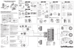
RF Module with Antenna
for EL Models
H2
100A
UD
J500
Model RFMODKT (390 MHZ)
RFMODKT3 (315 MHZ)
J403
J201
MIC
D300
J406 LCD
J405
H2
100A
UD
Caution!
D2
A static discharge can
DAMAGE circuit boards.
Denotes
315MHz
J301
D153
D102
3D2
100
16B
J401
H2
100A
UD
3D2
100
16B
J404
3D2
100
16B
J400
J300
{()){}}]{{}} {{{{(())}}}}}} }}}{{ }{}} {}{}}}}))))){{{}))))){{}}}
J407
3D2
100
16B
DEVICE 1,2
D514
D513
BT300
3D2
100
16B
SW300
DEVICE 3,4
J402 LEDJ200 SPKR
OV UV
J407
J400
J400
+
J400 Position
RF Module
Device 1
Avoid any metallic surface around
the antenna. Make sure antenna
connections are tight!
Back of RF Module
1 Disconnect power to the unit!
2 Unlock and open the unit.
3 Place RF module in J400 Plug - Device 1
or J407 Plug - Device 3. (4 screws per
board, screws are critical for proper
operation).
4 Cable MUST go through the conduit hole.
RG-6 Coaxial Cable
5 Test the module by pressing the
appropriate transmitter button once so
that the new module is automatically
detected.
100 Feet
Maximum
EL25
Optional Passport Remotes
J407 Position
Device 3
Mini 3-Button
Security+ ®
390MHz
Remotes
(For use
with Model
RFMODKT)
Mini 3-Button
Security+ ® with
HID proximity sensor
1-Button
Security+ ®
2-Button
Security+ ®
4-Button
Security+ ®
CPT1
CPT2
CPT4
CPTK33 CPT33PH CPT13 CPT23
CPT43
CPTK3 CPT3PH
315MHz
Remotes
(For use
with Model
RFMODKT3)
EL25