1
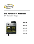
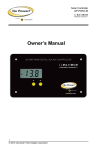
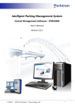
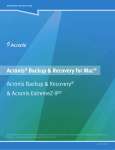
Go Power! Manual
GP-SW150 Inverter
GP-SW300 Inverter
Go Power! Electric Inc.
PO Box 6033
Victoria, BC V8P 5L4
Tel: 866-247-6527
Fax: 866-607-6527
Email: [email protected]
Go Power! SW150, SW300 Inverter
Owner’s Manual
Table of Contents
1.
INTRODUCTION ........................................................................3
2.
SPECIFICATIONS......................................................................3
3.
NAME AND MAIN FUNCTION ...................................................4
4.
INSTALLATION .........................................................................7
5.
OPERATION ..............................................................................9
6.
OPERATING LIMITS................................................................10
7.
TROUBLESHOOTING .............................................................10
8.
MAINTENANCE .......................................................................11
9.
WARRANTY.............................................................................11
Go Power! Electric Inc.
PO Box 6033
Victoria, BC V8P 5L4
Toll Free Tel: 866-247-6527
Toll Free Fax: 866-607-6527
Email: [email protected]
GP Electric 05.05 Rev 2.3
GP-SW150_300 InstallGuide.doc
2
Go Power! SW150, SW300 Inverter
Owner’s Manual
1. Introduction
The Go Power! Sine Wave series models are used in a wide range of applications
including remote homes, RVs, sailboats and powerboats. It will operate most televisions
and VCRs, personal computers, small appliances and tools such as drills, sanders,
grinders, mixers and blenders. The inverter must have a greater power rating than the
load it is providing power to. To get the most out of the power inverter, it must be installed
and used properly. Please read the instructions in this manual before installing and using
this model.
2. Specifications
2.1 GP-SW150 W Inverter
Model No.
Continuous Output Power
Surge Rating
Output Waveform
Output Voltage ± 3%
Output Frequency ± 0.05%
Input Voltage
Efficiency
No Load Current Draw / Powersave
Protection
Low Battery Alarm ± 2%
Low Battery Shut-Down ± 2%
Operating Temperature Range
Storage Temperature Range
Cooling
AC Receptacle
Dimensions (LxWxH) mm
inches
Weight kg / lbs
Warranty
Inverter Install Kit
GP-SW150-12
GP-SW150-24
150 W
260 W
Sine Wave <3% THD
115 VAC RMS
50 / 60 Hz adjustable
10.5-15 VDC
21.0-30.0 VDC
80-90%
0.20 A
0.15 A
Overload, Short Circuit, Reverse Polarity (Fuse),
Over / Under Voltage, Over Temperature
10.5 V
21.0 V
10.0 V
20.0 V
0 - 40°C / 32°F - 104°F
-30°C - 70°C / -22°F - 158°F
Thermostatically Controlled Fan
Dual GFCI
200 x 132 x 72
8 x 5.3 x 2.9
2.7 / 5.9
2 Years
Included
2.2 GP-SW300 W Inverter
Model No.
Continuous Output Power
Surge Rating
Output Waveform
Output Voltage ± 3%
Output Frequency ± 0.05%
Input Voltage
Efficiency
No Load Current Draw /
Powersave
Protection
Low Battery Alarm ± 2%
Low Battery Shut-Down ± 2%
Operating Temperature Range
Storage Temperature Range
Cooling
AC Receptacle
Dimensions (LxWxH) mm
inches
Weight kg / lbs
Warranty
Inverter Install Kit
GP300-12
GP300-24
300 W
450 W
Sine Wave <3% THD
115 VAC RMS
50 / 60 Hz adjustable
10.5-15 VDC
21.0-30.0 VDC
80 - 90%
0.26 A
0.23 A
Overload, Short Circuit, Reverse Polarity (Fuse),
Over/Under Voltage, Over Temperature
10.5 V
21.0 V
10.0 V
20.0 V
0 - 40°C / 32°F - 104°F
-30°C - 70°C / -22°F - 158°F
Thermostatically Controlled Fan
Dual GFCI
237 x 155 x 72
9.3 x 6.1 x 2.8
3.5 / 7.7
2 Years
Included
3
Go Power! SW150, SW300 Inverter
Owner’s Manual
3. Name and main function
3.1 Front view GP-SW150:
a. AC outlet
c. Remote port
b. ON /OFF switch
d. Power status LED
a) AC outlet:
Outlet sockets available: North America
b) ON / OFF switch:
Power ON/OFF switch, leave in the OFF position during installation.
c) Remote port
d) Power status
4
Go Power! SW150, SW300 Inverter
Owner’s Manual
3.2 Front view GP-SW300:
a. ON /OFF switch
c. AC outlet
c. Remote port
d. Power status LED
a) ON / OFF switch:
Power ON/OFF switch, leave in the OFF position during installation.
b) AC outlet:
Outlet sockets available:
North America
c) Remote port.
d) Power status LED.
5
Go Power! SW150, SW300 Inverter
Owner’s Manual
3.3 Rear view GP-SW150:
a. Ventilation port
b. DC Input Cables
d. Chassis ground lug
Warning!
Operation of the
inverter without a
proper ground
connection may
result in an
electrical safety
hazard.
a) Ventilation ports:
Do not obstruct, allow at least 1 inch for air flow.
b)
DC Input Cables:
Connect to battery or other power source: black is negative (-), red is positive (+). A
reverse polarity connection will blow the internal fuse and may damage inverter
permanently.
c) Chassis ground or to vehicle chassis using # 8 AWG wire.
6
Go Power! SW150, SW300 Inverter
Owner’s Manual
3.4 Rear view GP-SW300:
b. Ventilation ports
a. Chassis ground
c. Battery terminal
a) Chassis ground or to vehicle chassis using # 8 AWG wire.
Warning!
Operation of the
inverter without a
proper ground
connection may
result in an
electrical safety
hazard.
b) Ventilation ports:
Do not obstruct, allow at least 1 inch for air flow.
c) Battery terminals:
Connect to 12 V battery or other 12 V power source: [+] is positive and [-] is
negative. A reverse polarity connection will blow the internal fuse and may
damage inverter permanently.
4. Installation
4.1 Where to install
The power inverter should be installed in a location that meets the following
requirements:
Caution
Do not connect this inverter and another AC source (generator or utility power) to the AC
wiring or AC loads at the same time. Doing so will destroy the inverter and void the
warranty, regardless whether the inverter is switched on or off. If you are using more than
one AC source for the AC wiring or AC loads, it is highly recommended that you install an
automatic transfer switch (GP-TS), available from Go-Power Electric Inc.
a) Dry - Do not allow water to drip or splash on the inverter.
b) Cool - Ambient air temperature should be between 0°C and 40°C (the cooler the
better).
c) Ventilated - Allow at least two inches of clearance around the inverter for air flow.
Ensure the ventilation openings on the rear and bottom of the unit are not
obstructed.
d) Safe - Do not install the inverter in the same compartment as batteries or in any
compartment capable of igniting flammable liquids such as gasoline.
e) Inverter should be located within 10 feet of the batteries.
7
Go Power! SW150, SW300 Inverter
Owner’s Manual
4.2 Hook-up and testing
Caution!
A reverse polarity
connection will blow a
fuse in the inverter and
may permanently
damage the inverter.
Damage caused by
reverse polarity
connection is not
covered by our
warranty.
1. Unpack and inspect your Go Power! Inverter, check to see that the power switch
is in the OFF position.
2. Connect the negative cable (black) to the negative terminal of the battery. Make a
secure connection.
Caution! Loose connections result in excessive voltage drop and may cause
overheated wires and melted insulation.
3. Before proceeding further, carefully check that the cable you have just connected,
connects from the negative terminal of inverter to the negative output terminal of
the power source.
4. Install the recommended inverter fuse in positive lead. Fuse should be located
within 12” of battery. Ensure all connections are tight and secure. (See 4.3)
5. Connect the positive cable (red) to the positive terminal of the battery. Make a
secure connection.
Warning!
You may observe a
spark when you
make the positive
connection since
current may flow to
charge capacitors in
the power inverter.
Do not make this
connection in the
presence of
flammable fumes, as
explosion or fire may
result.
6. Set the power switch to the ON position. Check indicator on the front panel of
the inverter to ensure that it is red.
7. Set the power inverter switch to the OFF position. The indicator light may blink
and the internal alarm may sound momentarily. This is normal. Plug the test load
into the AC receptacle on the front panel of the inverter.
8. Set the power inverter switch to the ON position and turn the test load on; the
inverter should supply power to the load. If you plan to measure the output voltage
of the inverter, a true r.m.s. meter must be used for accurate readings.
4.3 Cables
Please use a 35 Amp fuse (not included) with the supplied #10 Cable. Install the inverter
fuse into the positive lead. Fuse should be located within 12” of battery. Ensure all
connections are tight and secure.
4.4 Grounding
Warning!
Do not operate the
power inverter
without connecting it
to ground. Electrical
shock hazard may
result.
The power inverter has a lug on the rear panel: “Chassis Ground.” This is to connect the
chassis of the power inverter to the ground. The ground terminals in the AC outlets on the
front of the inverter are also connected to the ground lug.
If available, the chassis ground lug should be connected to a ground point, which will vary
depending on where the power inverter is installed. In a vehicle, connect the chassis
ground to the chassis of the vehicle. In a boat, connect to the boat’s grounding systems.
In a fixed location, connect the chassis ground lug to earth.
The neutral (common) conductor of the power inverter AC output circuit is not bonded to
the chassis ground. Therefore, when the chassis is connected to ground, the neutral
conductor will not be grounded.
At no point should the chassis ground and the neutral conductor of the inverter be bonded.
Bonding the chassis ground and the neutral conductor of the inverter or connecting the
inverter to household or recreational AC distribution wiring will damage the unit and void
the warranty.
8
Go Power! SW150, SW300 Inverter
Owner’s Manual
Caution!
The negative DC input of the power inverter is connected to the chassis. Do not install the
power inverter in a positive ground DC system. A positive ground DC system has the
positive terminal of the battery connected to the chassis of the vehicle or to the grounding
point.
5. Operation
To operate the power inverter, turn it on using the ON/OFF switch on the front panel. The
power inverter is now ready to deliver AC power to your loads. If you are operating
several loads from the power inverter, turn them on separately after the inverter has been
turned on. This will ensure that the power inverter does not have to deliver the
starting-currents for all the loads at once.
5.1 Operating On/Off Switch
The ON/OFF switch turns the control circuit in the power inverter ON and OFF. It does
not disconnect power from the power inverter.
When the switch is in the OFF position, the power inverter draws no current from the
battery. When the switch is in the ON position but with no load, the power inverter draws
approximately 0.20 A from the battery.
5.2 Power Status
The power status LED indicates the operating state of the inverter. If the LED is green,
then the inverter is in operational mode and producing approximately 115 V AC. If the
LED is red or flashing red, then the inverter is in fault mode and there is no AC output.
Some common faults include:
5.2.1 Over voltage indicator (Red LED Blinking Fast)
The over voltage indicator indicates that the power inverter has shut itself down because
its input voltage has been over 16.5 VDC for the 12 V and 32.0 VDC for the 24 V.
5.2.2 Under voltage indicator (Red LED Blinking Slowly)
The under voltage indicator indicates that the power inverter has shut itself down because
its input voltage has been lower than 10.0 VDC for the 12 V and 20.0 VDC for the 24 V.
5.2.3 Over temp indicator: (Red LED Blinking Intermittently)
The over temp indicator indicates that the power inverter has shut itself down because it
has become overheated. The power inverter may overheat because it has been operated
at power levels above its rating, or because it has been installed in a location which does
not allow it to dissipate heat properly. The power inverter will restart automatically once it
has cooled off.
5.2.4 Overload indicator: (Red LED Solid)
The overload indicator indicates that the power inverter has shut itself down because its
output circuit has been short circuited or drastically overloaded. Switch the ON/OFF switch
to OFF, correct the fault condition, and then switch the ON/OFF switch back to ON.
5.3 Resetting Faults
Any of the inverters protection faults can be re-set by turning the inverter off for five
seconds and then turning the inverter on again. The GP-SW150 can also re-set any of its
protection faults using the optional remote on/off switch to turn the inverter off and then on
again.
9
Go Power! SW150, SW300 Inverter
Owner’s Manual
5.4 Remote
A user supplied remote option is available. When the on/off button is put to the remote
setting, the inverter will only work if a connection is made between the two terminals of the
remote input. A small screwdriver may be used to tighten the two terminals. A switch may
be placed between the two terminals and the inverter will now be turned off via the switch.
It is recommended that #18 gauge wire no more that 150 feet (terminal to terminal) be
used for this application.
6. Operating limits
6.1 Power output:
Some induction motors used in refrigerators, freezers, pumps, and other motor-operated
equipment require very high surge currents to start. The power inverter may not be able to
start some of these motors even though their rated current draw is within the power rating
of inverter. Televisions and computer monitors may surge up to four times their rated
power on startup, which may result in the inverter showing an overload fault.
6.2 Input voltage:
The power inverter will operate from input voltage ranging 10 V – 15 V (12 V) /
20 V – 30 V (24 V). The power inverter will shut down if the input voltage drops below
10 / 20 V. This protects your battery from being over discharged.
The power inverter will also shut down if the input voltage exceeds 16 / 32 V. This
protects the inverter against excessive input voltage. Although the power inverter
incorporates protection against over voltage, it may still be damaged if the input voltage is
allowed to exceed 20 / 40 V.
7. Troubleshooting
7.1 Common problems
Television interference: Operation of the power inverter can interfere with television
reception on some channels. If this situation occurs, the following steps may help to
alleviate the problem.
• Make sure that the chassis ground lug on the back of the power inverter is solidly
connected to the ground system of your vehicle, boat or home.
• Do not operate high power loads with the power inverter while watching television.
• Make sure that the antenna feeding your television provides an adequate ("snow
free") signal and that you are using good quality cable between the antenna and the
TV.
• Move the television as far away from the power inverter as possible.
• Keep the cables between the battery and the power inverter as short as possible
and twist them together with about 2 to 3 twists per foot. This minimizes radiated
interference from the cables.
10
Go Power! SW150, SW300 Inverter
Owner’s Manual
7.2 Troubleshooting guide
Problem and Symptoms
No output voltage, red LED blinking
fast
Possible Cause
High input voltage
No output voltage, red LED blinking
slowly
No output voltage, load in excess of:
150 W. Red LED blinking
intermittently
No output voltage, load less than:
150 W. Red LED blinking
intermittently
No output voltage, red LED solid
Poor DC wiring, poor
battery condition.
Thermal shutdown
No output voltage, red LED blinking
slowly
No output voltage, previous solutions
are not working
Thermal shutdown
Overload
Low input voltage
Inverter switched off.
No power to inverter
Car lighter fuse open
Internal fuse open
Reverse DC polarity
No output voltage, Over Load
indicator ON.
Short circuit or wiring
error.
Solution
Make sure that inverter is connected to 12
V battery. Check regulation of charging
system.
Use proper cable and make solid
connections. Use new battery.
Allow inverter to cool off. Reduce load if
continuous operation required.
Improve ventilation, make sure ventilation
openings in inverter are not obstructed,
reduce ambient temperature.
Reduce load
Recharge battery, check connections and
cable.
Turn inverter ON. Check wiring to inverter.
Replace
Have qualified service technician check and
replace.
Have qualified service technician check and
replace fuse, OBSERVE CORRECT
POLARITY.
Check AC wiring for short circuit or
improper polarity (hot and neutral reversed).
8. Maintenance
Very little maintenance is required to keep your inverter operating properly. You should
clean the exterior of the unit periodically with a damp cloth to prevent accumulation of
dust and dirt. At the same time, tighten the screws on the DC input terminals.
9. Warranty
We warrant this product against defects in materials and workmanship for a period of two
years from the date of purchase and will repair or replace any defective Go Power!
Inverter when directly returned, postage prepaid, to manufacturer. This warranty will be
considered void if the unit has suffered any obvious physical damage or alteration either
internally or externally and does not cover damage arising from improper use such as
plugging the unit into an unsuitable power sources, attempting to operate products with
excessive power consumption requirements, reverse polarity, or use in unsuitable
climates.
This is the only warranty and the company makes no other warranties, express or implied,
including warranties of merchantability and fitness for a particular purpose. Repair or
replacement are your sole remedies and shall not be liable for damages, whether direct,
incidental, special or consequential, even though cause by negligence or other fault.
11