1
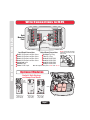
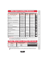
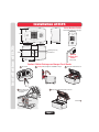
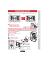
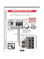
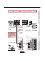
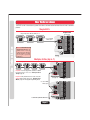
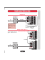
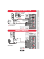
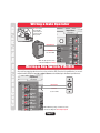
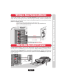
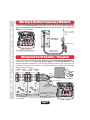
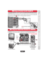
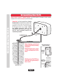
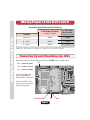
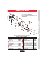
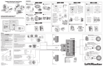
®
™
EL25 Installation Manual
Telephone entry/access control system with a 25 directory code capacity
© 2005 The Chamberlain Group, Inc.
All Rights Reserved
Table of Contents
Wire Type
Wire Connections to EL25 (Factory Settings for Relays)
Wire Specs and Run Distances
Power Wire Specs and Run Distances
2
3
3
Mounting the Unit
Installation of the EL25
Rotating the Keypad for Vertical Mounting
4-5
5
Phone Lines
Wiring 1 EL25 to the Telco Line (Alarm System Position)
Wiring Multiple EL25 Units to the Telco Line
Wiring with No Telco Line
Wiring to Dedicated Telco line
Wiring to an Internal Phone System
6
7
8
9
10
External Devices
Wiring a Door Strike Lock
Wiring a Maglock
Wiring a Gate Operator
Wiring a Key Switch/PIR/REX
Wiring a Door Sensing Device
Wiring the AutoCall Feature
Wiring a Radio Frequency Module (RF) (Optional RF Module(s) Needed)
Wiegand Card Reader / Keypad (Optional Wiegand Module(s) Needed)
Wiring a Postal Lock Switch
Wiring an Internal Camera (CCTV) (Optional CCTV Module Needed)
11
11
12
12
13
13
14
14
15
15
Grounding the Unit
Grounding the EL25
16
Power
Wiring Power to the EL25 and Powering Up the Unit
17-18
Programming Adjustments
19
19
Adjust Microphone / Speaker Volume
“Multiple Unit” Set-Up
Troubleshooting
20
Troubleshooting
Repair Parts
21
EL25 Repair Parts
“Your” Set-Up
“Your” System Diagram and Wiring Configuration
22-23
Accessories
24
Accessories
FCC and DOC and Appendix
25
26-27
FCC and DOC Requirements
Appendix
Page 1
Wire Connections to EL25
Wire Connections to EL25
5
3
8
6
2
11
12
7
9
1
13
Ground
20-Pin Input
to Main Board
14-Pin Output
to Main Board
Input Board Connections
1
2
3
4
5
6
7
Output Board Connections
8 Resident Tip / Ring
Door 1 Exit Request and Door Status
9 Telco Tip / Ring
Door 2 Exit Request and Door Status
10
Door 3 Exit Request and Door Status
Relay 4, NO,NC,COM
11 Relay 3, NO,NC,COM
Door 4 Exit Request and Door Status
12 Relay 2, NO,NC,COM
Postal Lock Input
13 Relay 1, NO,NC,COM
AutoCall Input
Power 12 VAC Input
Note: All relays are factory set to “Strike” and “10 sec.”
Do Not overload the removable
terminal block connectors. One
wire per hole.
Optional Modules
Caution! A Static Discharge
can Damage Circuit Boards
RG-59u
Coaxial
Connector
RG-6 Coaxial
Connector
P12V
P5V
DATA 0
DATA 1
LED
COM
J2
COM
LED
DATA 1
DATA 0
P5V
P12V
CCTV
Optional CCTV
Module (Page 15)
(Replaces Call
Button Board)
Optional RF
Module (Page 14)
(Fits in J400
and/or J407)
Main
J1
Optional Wiegand
Module (Page 14)
(Fits in J400
and/or J407)
Page 2
J407
J400 Circuit
Board
Optional Module Mounting Positions
Wire Connections to EL25
Input Board
Back
Mounting
Plate
Output Board
10
4
Wire Specs and Run Distances
Residence and Telco Phone Lines
Door Strike
Magnetic Lock
Dry Contact Closure (Most Gate Operators)
Exit Request (REX) / Auxiliary Open Devices
AutoCall
Door Status Sensor
Barium Ferrite and Wiegand Readers
Proximity Readers
Radio Frequency Module (RF)
Postal Lock
2 Twisted Pairs
18-24 AWG Shielded
2 -Conductor
18-22 AWG Shielded
2 -Conductor
18-22 AWG Shielded
2 -Conductor
18-24 AWG Shielded
2 -Conductor
18-24 AWG Shielded
2 -Conductor
18-24 AWG Shielded
2 -Conductor
18-24 AWG Shielded
5 -Conductor
18-24 AWG Shielded
5 -Conductor
22 AWG Shielded
RG-6 Coaxial
75 ohm
2 -Conductor
18-24 AWG Shielded
Recommended
Wire Type
Page
Belden #7838A
6-10
Alpha #1292C
11
Alpha #1292C
11
Alpha #1292C
12
Alpha #1292C
12
Alpha #1292C
13
Alpha #1292C
13
500 feet
Alpha #1295C
14
500 feet
Alpha #1295C
14
100 feet
Belden BRG6 Cable
14
Alpha #1292C
15
5000 feet
1000 feet
Belden #9240
BNC Connectors
CCTV Camera (Optional)
Single Conductor
RG-59u Coaxial
(Monitor with a
.25 volt p-p
composite signal
sensitivity)
(Amphenol #31-71008
or equivalent)
Grounding the Chassis
12 AWG Copper
12 feet
Belden #9912
15
16
Note: Use metal conduit - run wires in metal conduit instead of PVC pipe. Wires run in PVC conduit may experience
interference. Metal conduits also add extra protection against lightning strikes.
Never run Data wires and High Voltage wires in the same conduit. The high voltage wires may interfere with the data
wires, possibly causing the system to malfunction.
Power Wire Specs and Run Distances
Distance
Under 30 Feet
30 - 75 Feet
75 - 250 Feet
12 VAC Power (Included)
12 VDC Power (Not Provided)
2 -Conductor Shielded
14 AWG
14 AWG
14 AWG
2 -Conductor Shielded
16 AWG
14 AWG
N/A
Always provide power from a dedicated source. Plug provided transformer into an outlet wired to its own 10 Amp minimum
circuit breaker. This will prevent two problems:
1 Other equipment cannot introduce spikes, noise, surges, or dips into the power circuit that will affect the system.
2 The system's operation will not be affected if any other equipment develops a short circuit across the power line.
Page 3
Wire Specs and Run Distances
Wire Specs and Run Distances
Use this chart to pull wires in preparation of your installation:
Wire
Maximum
Description of Wire Run
Specification
Distance
Installation of EL25
Vertical Mounting Position
with rotated keypad (see next page)
6 in.
3.9 in.
10.25 in.
Mounting Holes (4)
Conduit Hole
3.075 in.
Optional
Pedestal Post
Mount
(Gooseneck)
5.125 in.
Caution! A Static Discharge can Damage Circuit Boards
1 Unlock Unit
2 Carefully Lift Cover Up then Slide Out on Hinges
4 Line up Notch with
Screw and Push
Hinge Out
3 Unplug the 2 Main Harnesses
5 Remove Back Mounting Plate from Cover
Screw
Contiuned
Notch
Page 4
Installation of EL25
Installation of EL25
3.075 in.
Installation of EL25
6 Secure Back Mounting Plate to Surface or Pedestal Post
in 4 Places.
7 Run All Wires Through Conduit Hole for Connections.
Keep Wires Neat! Use zip ties if necessary.
8 Reverse the Sequence to Reassemble Unit.
DO NOT Pinch Wires when
Closing and Locking the Unit!
Do Not overload the removable
terminal block connectors. One
wire per hole.
Rotating the Keypad for Vertical Mounting
Caution! A Static Discharge can
Damage Circuit Boards
1 Disconnect all Plugs from Main Circuit Board and
Remove Board. (4 Screws)
2 Remove Bracket. (4 Screws)
3 Keypad
3 Rotate Keypad 90 Degrees Clockwise.
4 Reverse the Sequence to Reassemble Unit.
ONLY Vertical
Mounting Position
2 Bracket
1 Main Circuit Board
Note: Bracket notch
lines up with ribbon
cable on keypad.
Main Circuit Board Connections
J200 - Speaker
J402 - Light
J404 - Call Button Board
Page 5
J401 - Keypad
J406 - Light
J201 - Microphone
Installation of EL25
Installation of EL25
EL25 MUST
be Properly
Grounded!
See Page 16.
Wiring 1 EL25 to Telco Line
The bypass board allows the EL25 to be disconnected without interrupting normal telephone operation.
• When the EL25 unit is in use, the bypass switch must be set to the operate position.
Bypass Board
(Mount in the House)
Home Phone
OPERATE
Ring Tip
HOME
BYPASS
4 3 2 1
SYSTEM
Ring Tip
TELCO
Ring
Tip
Tip
Ring
(NOT Provided)
Important: The Voltmeter measurement
between the Tip and Ring should read
between 48 and 53 VDC.
Note: If the EL25 unit will be used in
conjunction with an alarm system,
you must connect the telephone line
to the alarm system first. If the units
are not connected in this order, they
will not operate properly.
Use 18-24 AWG
2 twisted pair
Do Not overload the removable terminal
block connectors. One wire per hole.
3
4
Resident
8 Ring
Tip
Telco
1
2
9 Ring
Tip
Output Board
(See page 2)
Page 6
NO
NC
Com
10
NO
NC
Com
11
NO
NC
Com
12
NO
NC
Com
13
Wiring a Single EL25
Never run Data wires and
High Voltage wires in the
same conduit. The high
voltage wires may interfere
with the data wires, possibly
causing the system to
malfunction.
Alarm System Position
Telco Entrance Box
Demarcation Point
Important: The Bypass
Board (located inside
the property) allows
access to the phone in
case the EL25 fails.
Relay 4 Relay 3 Relay 2 Relay 1
Wiring a Single EL25
• When the EL25 unit is disconnected, the bypass switch must be set to the bypass position.
Wiring Multiple EL25 Units to Telco Line
Up to 7 EL25s can share the same phone line. The bypass boards allow the EL25 units to be
disconnected without interrupting normal telephone operation.
• When the EL25 units are in use, the bypass switches must be set to the operate position.
Home Phone
OPERATE
Ring Tip
HOME
4 3 2 1
SYSTEM
OPERATE
Ring Tip
TELCO
SYSTEM
Important: The Bypass
Boards (located inside
the property)allow
access to the phone in
case any of the EL25s
fail.
Never run Data wires and
High Voltage wires in the
same conduit. The high
voltage wires may interfere
with the data wires, possibly
causing the system to
malfunction.
Last Bypass Board
BYPASS
4 3 2 1
Ring Tip
HOME
Ring
Tip
Ring
Tip
Important: The Voltmeter
measurement between the Tip
and Ring should read between
48 and 53 VDC.
Bypass Board for Unit 2
BYPASS
BYPASS
Ring Tip
TELCO
Telco Entrance Box
Demarcation Point
Ring Tip
TELCO
Tip
Tip
Ring
Ring
Important: You must program the Unit ID's for
each EL25 wired in the series. See “Multiple
Unit Set-Up” page 19.
Use 18-24 AWG
2 twisted pair
C
Do Not overload the removable
terminal block connectors. One
wire per hole.
3
4
Resident
8 Ring
Tip
Telco
1
2
9 Ring
Tip
Unit ID 1
Output Board
C
C
C
(See page 2)
Page 7
1
2
Resident
8 Ring
Tip
Telco
3
4
9 Ring
Tip
Unit ID 2
Output Board
(See page 2)
NO
NC
Com
10
NO
NC
Com
11
NO
NC
Com
12
NO
NC
Com
13
Wiring Multiple EL25 Units
Bypass Board for Unit 1
Relay 4 Relay 3 Relay 2 Relay 1
Wiring Multiple EL25 Units
• When the EL25 units are disconnected, the bypass switches must be set to the bypass position.
No Telco Line
The EL25 can be a stand alone system that allows communication between the unit and a resident's
phones.
Single EL25
Output Board
Ringer Equivalence Number (REN) of “5”.
(See page 2)
Resident
8 Ring
Tip
Never run Data wires and
High Voltage wires in the
same conduit. The high
voltage wires may interfere
with the data wires, possibly
causing the system to
malfunction.
11
NO
NC
Com
12
NO
NC
Com
13
Multiple EL25s (Up to 7)
Ringer Equivalence Number (REN) of “5”.
Resident
8 Ring
Tip
Important: You must program the Unit ID's for each
EL25 wired in the series. See “Multiple Unit
Set-Up” page 19.
Telco
9 Ring
Tip
Unit ID 1
Output Board
Important: Only disable the Telco mode of the Unit
farthest away from the house. See “Disable Telco
Mode” page 54 in the Keypad Programming Guide.
NO
NC
Com
10
NO
NC
Com
11
NO
NC
Com
12
NO
NC
Com
13
NO
NC
Com
10
NO
NC
Com
11
NO
NC
Com
12
NO
NC
Com
13
(See page 2)
Resident
8 Ring
Tip
Telco
9 Ring
Tip
Unit ID 2
Output Board
to next EL25 (Unit ID 3 then 4 etc.)
Page 8
(See page 2)
Relay 1 Relay 2 Relay 3 Relay 4
Use 18-24 AWG
2 twisted pair
No Telco Line
9 Ring
Tip
NO
NC
Com
Relay 1 Relay 2 Relay 3 Relay 4
No Telco Line
Telco
10
Relay 1 Relay 2 Relay 3 Relay 4
Use 18-24 AWG
2 twisted pair
NO
NC
Com
Dedicated Telco Line
Single EL25
Never run Data wires and
High Voltage wires in the
same conduit. The high
voltage wires may interfere
with the data wires, possibly
causingthesystemto
malfunction.
NO
NC
Com
12
NO
NC
Com
13
Output Board
(See page 2)
Multiple EL25s (Up to 7)
Important: You must program the
Unit ID's for each EL25 wired in the
series. See “Multiple Unit Set-Up”
page 19.
to next EL25 (Unit ID 5 then 4 etc.
Unit ID 1 is farthest away from Telco Box)
Resident
8 Ring
Tip
Telco
9 Ring
Tip
Unit ID 6
Output Board
Use 18-24 AWG
2 twisted pair
Telco
9 Ring
Tip
Tip
Unit ID 7
Output Board
(See page 2)
Page 9
NO
NC
Com
11
NO
NC
Com
12
NO
NC
Com
13
NO
NC
Com
10
NO
NC
Com
11
NO
NC
Com
12
NO
NC
Com
13
(See page 2)
Resident
8 Ring
Tip
Ring
10
Relay 1 Relay 2 Relay 3 Relay 4
Telco Entrance Box
Demarcation Point
NO
NC
Com
Relay 1 Relay 2 Relay 3 Relay 4
Dedicated Telco Line
9 Ring
Tip
Tip
11
Dedicated Telco Line
Telco
NO
NC
Com
lay 1 Relay 2 Relay 3 Relay 4
Resident
8 Ring
Tip
Use 18-24 AWG
2 twisted pair
Ring
10
NC
Com
Telco Entrance Box
Demarcation Point
Internal Phone System
The EL25 can be wired to any Analog Trunk Input in a internal home phone system.
Single EL25
Resident
8 Ring
Tip
Ring
EX 3Analog
Tip
Tip
T
R
Ring
Telco
9 Ring
Tip
10
EX 4
NO
NC
Com
11
NO
NC
Com
12
NO
NC
Com
13
Use 18-24 AWG
2 twisted pair
Never run Data wires and
High Voltage wires in the
same conduit. The high
voltage wires may interfere
with the data wires, possibly
causing thesystem to
malfunction.
Output Board
(See page 2)
Multiple EL25s (Up to 7)
Resident
8 Ring
Tip
Telco
9 Ring
Tip
Use 18-24 AWG
2 twisted pair
EX 3Analog
R
Tip
Ring
EX 4
Internal
Phone System
Analog
Trunk Input
Page 10
NO
NC
Com
11
NO
NC
Com
12
NO
NC
Com
13
NC
Com
Telco
9 Ring
Tip
Unit ID 7
Output Board
(See page 2)
10
NO
NC
Com
11
NO
NC
Com
12
NO
NC
Com
13
ay 1 Relay 2 Relay 3 Relay 4
EX 1
Tip
Telco Entrance Box
Demarcation Point
T
10
(See page 2)
Resident
8 Ring
Tip
2
Ring
Unit ID 6
Output Board
NO
NC
Com
Relay 1 Relay 2 Relay 3 Relay 4
to next EL25 (Unit ID 5 then 4 etc.
Important: You must program the Unit
ID's for each EL25 wired in the series. Unit ID 1 is farthest away from Telco Box)
See “Multiple Unit Set-Up” page
19.
Internal Phone System
EX 1
Internal Phone System
2
Telco Entrance Box
Demarcation Point
NC
Com
Analog
Trunk Input
lay 1 Relay 2 Relay 3 Relay 4
Internal
Phone System
Wiring a Door Strike Lock
AC or DC
Power
Siemens S10K30 MOV
(Metal Oxide Varistor)
or equivalent.
For DC Power: Install a
1N4005 diode or equivalent.
–
+
esident
8 Ring
For AC Power: Install
Tip a
Common
Telco
Use 18-22 AWG
9
Ring
Tip
Do Not use the EL25's power
supply for the Door Strike.
Note: The door strike
can be connected to
any of the 4 Relays.
NO
NC
Com
10
NO
NC
Com
11
NO
NC
Com
12
NO
NC
Com
13
Wiring a Maglock
Output Board
(See page 2)
DC Power
Normally Closed
+
–
Use 18-22 AWG
Common
Do Not use the EL25's power
supply for the Maglock.
Note: The maglock
can be connected to
any of the 4 Relays.
Page 11
10
esident
8 Ring
Tip
NO
NC
Com
11
Telco
NO
NC
Com
12
NO
NC
13
9
Ring
Tip
Relay 4 Relay 3 Relay 2 Relay
Install a 1N4005 diode
or equivalent.
NO
NC
Com
Door Strike Lock / Maglock
Normally Open
Output Board (See page 2)
Relay 4 Relay 3 Relay 2 Relay 1
Door Strike Lock / Maglock
Do Not overload
the removable
terminal block
connectors. One
wire per hole.
Output Board
(See page 2)
Normally Open
Common
NO
NC
Com
10
esident
8 Ring
Tip
NO
NC
Com
11
Telco
NO
NC
Com
12
NO
NC
13
Use 18-24 AWG
9
Note: The gate operator can be
connected to any of the 4 Relays.
Ring
Tip
C
Wiring a Key Switch/PIR/REX
Any auxiliary opening device such as a key switch or PIR (Passive Infrared Device), or an exit
request button (REX) that provides contact closure can be hooked up to the Door Input terminals.
Input Board
4
Exit Req 4
Com
Door Stat 4
3
Exit Req 3
Com
Door Stat 3
2
Exit Req 2
Com
Door Stat 2
1
Exit Req 1
Com
Exit Request
Common
Use 18-24 AWG
Power Autocall Postal
oor 1 Door 2
Door 3
Door 4
(See page 2)
5
6
7
Note: Additional opening or exit devices can be
connected to any of the 4 Exit Request inputs.
Page 12
Gate Operator / Key Switch / PIR / REX
Do Not overload
the removable
terminal block
connectors. One
wire per hole.
Relay 4 Relay 3 Relay 2 Relay
Gate Operator / Key Switch / PIR / REX
Wiring a Gate Operator
The EL25 can monitor the position of up to four doors/gates and may react to a change in their
status with one of the relays (not set as a control relay). For example, if a door is pried open or is
held open after its relay deactivates, the unit will record the breach in its transactions and can
perform the following actions:
• Call the main residence phone and report the status of the door.
• Energize a relay to activate an alarm device such as a siren, light, or CCTV camera.
• Main use is to terminate strike time early.
Input Board
3
Exit Req 3
Com
Door Stat 3
2
Exit Req 2
Com
Door Stat 2
1
Exit Req 1
Com
Power Autocall Postal
Door 4
Exit Req 4
Com
Door Stat 4
or 1 Door 2
4
Door 3
(See page 2)
Common
5
Door Status
6
Use 18-24 AWG
7
Note: Additional sensing devices can be
connected to any of the 4 Door Stat inputs.
Wiring the AutoCall Feature
2
at 3
2
at 2
1
at 1
Power Autocall Posta
Using the AutoCall feature, the EL25 will automatically call the main residence phone when a
driveway sensor is activated (any device that provides a contact closure ). For example, when a
visitor drives over a loop sensor that is connected to the AutoCall feature, the EL25 will call the main
residence phone automatically so the visitor can speak to the resident without pressing the call
button on the unit.
5
In
Com
6
In
Com
7
Neg
+12 V
Input Board
In
Common
Use
18-24 AWG
Loop
Detector
SeL
no
so
op
r
(See page 2)
Page 13
Door Sensing Device / AutoCall
Door Sensing Device / AutoCall
Wiring a Door Sensing Device
An optional radio frequency module and a remote antenna can be installed if the residents will
access a controlled area with a transmitter. Refer to instructions supplied with the optional RF
Module for more information.
Avoid any metallic
surface around the
antenna.
RG-6
Coaxial
Connector
1 RF Module Kit
Part # RFMODKT
Main
J407
J400 Circuit
Device 3 Device 1
Board
Remote Antenna
RF Module(s) will fit in
J400 as Device 1 and/or J407 as Device 3.
(4 Mounting Screws per Board)
RG-6 Coaxial Cable
100 Feet Maximum
Wiegand Card Reader / Keypad
Wiegand card readers and keypads can be connected to either of 2 optional wiegand modules that
can be placed in the EL25. Each wiegand module supports two card readers/keypads. Some
wiegand card reader/keypads have a sixth blue wire. Do Not connect this blue wire to the EL25.
Insulate this wire from the unit to prevent a short (Refer to instructions supplied with your wiegand
device for more information).
J407 Position
Device 4
P12V
P5V
DATA 0
DATA 1
LED
COM
J2
J400 Position
Device 3 Device 2
P12V
P5V
DATA 0
DATA 1
LED
COM
COM
LED
DATA 1
DATA 0
P5V
P12V
J1
J2
Device 1
Black
Brown
White
Green
COM
LED
DATA 1
DATA 0
P5V
P12V
Use 18-24
AWG
Card Reader is Wired to Device 1
Red Power
Blue (Insulate this wire).
J1
Shield
(Attach to the
EL25 ground).
1 Wiegand Module Kit
Part # WOMODKT
Wiegand Modules will fit in
J400 as Device 1 (J1) and 2 (J2)
and/or
J407 as Device 3 (J1) and 4 (J2).
(4 Mounting Screws per Board)
Page 14
J407
Main
Circuit
J400 Board
RF Module / Card Reader / Keypad
RF Module / Card Reader / Keypad
Wiring a Radio Frequency Module
The Post Office requires installation of a postal lock if postal carriers do not have access to a
controlled area. Contact the local post office and arrange for them to install the postal lock while
you are on site. The postal lock requires a switch to activate one of the four relays (Configurable
with programming number 669,
69 page 58 in the Keypad Programming Manual).
Exit Req 3
Com
Door Stat 3
Exit Req 2
Com
Door Stat 2
Exit Req 1
Com
Door Stat 1
Power Autocall Postal
Door Stat 1
5
In
Com
6
In
Com
7
Neg
+12 V
In
Common
Use
18-24 AWG
N.C.
Switch
Input Board
Do Not overload the removable
terminal block connectors. One wire
per hole.
(See page 2)
Wiring an Internal Camera (CCTV)
An Optional CCTV (Close Circuit Television) Camera can be installed inside the EL25 unit replacing
the Call Button Board, refer to instructions supplied with the Camera kit for more information.
Contact your dealer/ installer
for more information
CCTV
Replaces
the Call
Button
Board.
(3 Screws)
Home Entertainment
System
RG-59u Coaxial Cable 1000 Feet Maximum
(Monitor with a .25 volt p-p composite signal sensitivity)
Low Lux DVR Color Camera Kit
Part # EL25DVRCAMKT
Black and White Camera Kit
Part # EL25BWCAMKT
Color Camera Kit
Part # EL25CCAMKT
A Closed Circuit Monitor
Page 15
Postal Lock Switch / CCTV Camera
Postal Lock Switch / CCTV Camera
Wiring a Postal Lock Switch
Grounding the EL25
Ensure that the system is grounded properly. The EL25 contains a number of static sensitive
components that can be damaged by static discharge.
Recommended and should be no further than
12 ft from the unit and use a minimum of 12
gauge wire in most cases. The type and length
of earth ground rods vary by region. Contact
the building inspector’s office in the
municipality where you plan to install the
unit for correct grounding materials and
installation procedures.
Green Ground
Wire
12 AGW Minimum
12 ft Maximum
Before digging, contact local
underground utility locating
companies.
Avoid damaging gas, power,
or other underground utility
lines.
Do Not ground the EL25 to a
pedestal post (gooseneck) if
one is used.
Earth Ground Rod
Page 16
Other Ground Sources
within 12 ft of Unit
Ground to
Existing
Electrical
System
Ground to
Metallic Cold
Water Pipe
Electrical
Panel
Grounding the EL25
Grounding the EL25
Important: An Earth Ground Rod is Strongly
Wiring Power to the EL25
The 110 VAC outlet must be dedicated to the EL25 ONLY . This outlet should be wired back to its
own 10 Amp minimum circuit breaker. This will prevent two problems:
1 Other equipment cannot introduce spikes, noise, surges, or dips into the power circuit.
On
Off
Off
Air (1)
Conditioner
Main
Room
Off
Conference
Room 1
On
EL25 MUST
be Properly
Grounded!
See Page 16.
Conference
Rm 2, 3
Off
12 VAC (Included)
On
Refer.
Bus 1, 2, 3
On
AC Power
Off
Connect the transformer into a 110 VAC outlet after all connections have been made. Any other type
of outlet will cause damage to the system.
EL25
Conference
Room 2
Eug. Rm
Oper. Rm
Comp.
Serve 2
Eug. Dept.
Manu. 1 Rm
110 VAC Outlet
xit Req 2
om
oor Stat 2
xit Req 1
om
oor Stat 1
Power Autocall Postal
xit Req 1
om
oor Stat 4
5
In
Com
6
In
Com
7
Neg
+12 V
Comp.
Serve 1
Main Dept.
Manu. 2 Rm
Dedicated 10 Amp Minimum
Circuit Breaker
Input Board (See page 2)
xit Req 3
om
oor Stat 3
Off
Air (2)
Conditioner
Polarity Does Not Matter
(See table on the next page for AWG)
12 VDC Power
(Not Provided)
Polarity Does
Not Matter
(See table on the
next page for AWG)
Page 17
Wiring Power to the EL25
across the power line.
Off
Wiring Power to the EL25
2 The system’s operation will not be affected if any other equipment develops a short circuit
Wiring Power to the EL25 (con’t)
Power Wire Specifications and Run Distances
12 VDC Power
(Not Provided)
Distance
2 -Conductor Shielded
2 -Conductor Shielded
Under 30 Feet
14 AWG
16 AWG
30 - 75 Feet
14 AWG
14 AWG
75 - 250 Feet
14 AWG
N/A
Caution: Not responsible for conflicts between the information listed in the above table and the requirements of your local
building codes. The information is for suggested use only. Check your local codes before installation.
Powering Up and Checking the LEDs
Plug the transformer into the 110 VAC outlet. Check the SYS PWR LEDs on the Main board.
ON
ON LED – Board has Power.
LO LED – Power is Too Low.
J406
HI LED – Power is Too High.
J401
J201
J400
If the LO or HI LED is still lit,
check the power connections,
wiring, and transformer.
J404
If the LO or HI LEDs are lit,
press the PWR MON RST
(Power Monitor Reset) button.
J402 J200
Hard Reboot
PWR MON RST
Page 18
HI
LO
Wiring Power to the EL25
Wiring Power to the EL25
12 VAC Power (Included)
Microphone/ Speaker / Multiple Units Set-Up
Adjust Speaker Volume:
18
Allows the visitor to hear the resident at the unit. Factory
Enter Programming Mode
Setting for the Speaker is “5”.
Factory Password
Programming Sequence
2 Short Beeps
Will be Heard
Exit Programming Mode
Set Speaker Level
(0=Mute, 1=Low....10=High)
3 Short Beeps
Will be Heard
Note: The visitor can adjust the speaker volume on unit with this key.
Unit will return to programmed volume setting when call is complete.
Adjust Microphone Volume:
19
Allows the resident to hear the visitor at the unit. Factory
Enter Programming Mode
Setting for the Microphone is “5”.
Factory Password
Exit Programming Mode
Programming Sequence
2 Short Beeps
Will be Heard
Set Microphone Level
(0=Mute, 1=Low....10=High)
3 Short Beeps
Will be Heard
For more information refer to the Keypad Programming Manual
If you make an error during the programming sequence,
press the asterisk key ( ) to start the programming sequence again.
*
“Multiple Unit” Set-Up
Up to seven (7) EL25s can be installed on a single telephone line. Each unit must have a“Unique
Unit ID” number and the “Number of Units in Chain” assigned to it. Unit ID #1 is always connected
to the residence.
Unique Unit ID Sequencial Order
Unit ID “1”
Residence
Unit ID “2”
Unit ID “3”
This must be performed on each unit in the chain. Factory
Enter Programming Mode
Unit ID “7”
Telco Entrance Box
Demarcation Point
Number of Units in Chain “7”
Set the Unit's ID Number and Number of Units in Chain:
Microphone/ Speaker / Multiple Units Set-Up
Adjust Microphone / Speaker Volume
2
Setting is “Unit ID 1” and “Number of Units in Chain 1”.
Programming Sequence
Factory Password
2 Short Beeps
Will be Heard
Set
Unit ID
(1 to 7)
Set Number
of Units
in Chain
(1 to 7)
For more information refer to the Keypad Programming Manual
Page 19
Exit Programming Mode
3 Short Beeps
Will be Heard
Troubleshooting
Common Mistakes
No power to EL25
• Check power at source. Power must come from a dedicated 110VAC outlet.
• The transformer's outlet should be wired to its own circuit breaker.
• Check “SYS PWR” LED indicators. If “LO” or “HI” are lit, press “PWR MON RST” button. If either of those two
LEDs are still lit, check transformer and outlet.
Door Strikes/Maglocks/Gate Operator not working
• Check power source. Strikes, Maglocks and Gate Operator must be powered independent from unit.
• Connect and test different Strike or Maglock. Make sure Strike or Maglock is not defective.
• Door Strike: Pin connections “NO” and “COM” at Relay terminal.
• Mag Lock: Pin connections “NC” and “COM” at Relay terminal.
• Gate Operator: Pin connections “NO” and “COM” at Relay terminal.
Postal Lock or AutoCall device not working
• Short “IN” and “COM” pin connections to verify functionality. If wiring is correct and device still does not
work, contact technical support.
Card Reader not communicating with EL25
• Check Wiegand reader module connections.
• Connect and test a functioning reader. Make sure reader is not defective.
• Did you add the card(s) to the database while in programming mode?
• Check card format compatibility. The EL25 is only compatible with 26 and 30-bit cards.
• Review the transactions using Versa XS, if applicable, and check whether card failed.
Phone not functioning with the EL25
• Did you wire the Bypass Board correctly? See page 7.
• Is Bypass Board switch set to “OPERATE”?
• Did you wire the surge suppressor correctly? See page 7.
• Using an alarm system? If so, see page 8.
• Using an alarm system on multiple unit configuration? If so, see page 9.
Aux Open / Exit Request device not working
• Did you assign a relay to the REX? See the EL25 Programming Manuals.
• Check connections at Door # terminal(s). Wires to “COM” and “EXT REQ #” connection.
Transmitter not working
• Did you use the correct coaxial cable? See page 3.
• Is the remote antenna installed correctly? Is it outside of the EL25 enclosure?
• Did you add the transmitter(s) to the database as a transmitter or a access card while in programming mode?
• Only Passport transmitters can be used.
Page 20
Troubleshooting
Troubleshooting
• Check for correct length and AWG of wires. See page 3.
• Check that wires are correctly inserted into the terminal blocks (not loose, no two sharing the same position).
• Check board markings for correct terminal block placements.
• Make sure high voltage and data wires do not share the same conduit.
• Use metal conduit, not PVC.
EL25 Repair Parts
Installation and Service Information are Available 6 Days a Week
4
6
5
Call our Toll Free Number 1-800-528-2806
Monday through Friday 5:00 am to 6:00 pm (Mountain Std. Time)
Saturday 7:00 am to 3:30 pm (MST)
www.chamberlain.com
1
21
12
2
EL25 Repair Parts
9
22
7
13
10
15
14
19
20
11
17
16
18
When ordering repair parts, Please supply the following information:
Part Number, Description and Model Number
Part Description
1
2
3
4
5
6
7
8
9
10
11
Silver Cover
Nickel Cover
Dark Gray Cover
Lens Black, Camera
Lens Clear, Camera
Actuator,Call Button, Silver
E-Ring, Call Button
Spring, Call Button
Gasket, Back
Assembly Lock EL25
Key
Assembly, Speaker EL25
Assembly, LED
Part Number
093D0341
093D0341-1
093D0341-2
108B0081
108B0081-1
101A0159
158A0094
177A0166
084B0081-1
002B0809
TBD Call
002B0639
002B0721
12
13
14
15
16
17
18
19
20
21
22
Part Description
Part Number
Assembly, Mic Cable, EL25
Gasket, Key Pad
Assembly Keypad 16 Button
Assembly EL25 Main Board
Assembly PCB Output Board
Assembly PCB Input Board
Assembly, Mounting Back, Silver EL25
Assembly, Mounting Back, Nickel EL25
Assembly, Mounting Back, Mist Gray EL25
Assembly, 20-Pin Cable, EL25
Assembly, 14-Pin Cable, EL25
Assembly, Call Button Board
Direct Connect Cable
002B0692
084C0087
180D0236
002B0735
002B0737
002B0736
002C0607
002C0607-1
002C0607-2
002B0705
002B0704
002B0731
002B0747
Page 21
EL25 Repair Parts
11
3
8
Your System Diagram
Your System Diagram
Your System Diagram
Page 22
Your Wiring Configuration
External Access Control Device (s) connected to optional board(s)
J400 Position
Device 1
Device 2 (Wiegand Only)
J407 Position
Device 3
Device 4 (Wiegand Only)
Relay Connections (Output Board)
Relay 1
Relay 2
Relay 3
Relay 4
Door Connections (Input Board)
Door 1
Connection
Postal
Lock
Door Sensor
and/or
Exit Device
Yes
No
Door 2
Connection
Door Sensor
and/or
Exit Device
AutoCall
Device
Door 3
Connection
Yes
No
Dealer / Installer
Page 23
Door Sensor
and/or
Exit Device
Door 4
Connection
CCTV
Camera
Door Sensor
and/or
Exit Device
Yes
No
Your Wiring Configuration
Your Wiring Configuration
Device 0 (Default Internal Keypad)
EL25 Accessories
Wiegand Module Kit
WOMODKT
Low Lux DVR Color Camera Kit
EL25DVRCAMKT
Color Camera Kit
EL25CCAMKT
RF Module Kit
RFMODKT
1
2
3
4
5
6
7
8
9
*
0
#
Wiegand Remote Keypad
ESSWOKSG
a
Vers
XS
Versa XS Software
VERSWR10
Page 24
1
2
3
4
5
6
7
8
9
*
0
#
Wiegand Remote Keypad/Prox Combo
HIDWOKPRO
EL25 Accessories
EL25 Accessories
Black and White Camera Kit
EL25BWCAMKT
FCC Requirements
The EL25 system complies with Part 68 of the FCC Rules. The label affixed to this equipment contains, among
other information, the FCC Registration Number and Ringer Equivalence Number (REN) for this equipment. You
must, upon request, provide this information to your telephone company.
The REN is useful to determine the quantity of devices you may connect to your telephone line and still have all
of those devices ring when your telephone number is called. In most, but not all areas, the sum of the RENs of
all devices connected to one line should not exceed five (5.0). To be certain of the number of devices you may
connect to your line, as determined by the REN, you should contact your local telephone company. They will tell
you what the maximum REN is for your calling area.
The following jacks must be ordered from the telephone company in order to interconnect this equipment with
the public communication network: None.
If your EL25 system causes harm to the telephone network, the Telephone Company may discontinue your
service temporarily. If possible, they will notify you in advance. If advance notice is not practical, you will be
notified as soon as possible. You will be informed of your right to file a complaint with the FCC.
Your Telephone Company may make changes in its facilities, equipment, operations or procedures that could
affect the proper functioning of your equipment. If they do you will be notified, in advance, to give you an
opportunity to maintain uninterrupted telephone service.
Connections to party lines are subject to state tariffs. Contact your local telephone company if you plan to use
this equipment on party lines.
This equipment cannot be used on public coin service lines provided by the telephone company.
DOC Requirements
Notice: The Canadian Department of Communications label identifies certified equipment. This certification
means that the equipment meets certain telecommunications network protective, operational, and safety
requirements. The Department does not guarantee the equipment will operate to the user’s satisfaction.
Before installing this equipment, users should ensure that it is permissible to be connected to the facilities of
the local Telecommunications Company. The equipment must also be installed using an acceptable method of
connection. In some cases, the company’s inside wiring associated with single line individual service may be
extended by means of a certified connector assemble (telephone extension cord). The customer should be
aware that compliance with the above conditions may not prevent degradation of service in some situations.
Repairs to certified equipment should be made by an authorized Canadian maintenance facility designated by
the supplier. Any repairs or alterations made by the user to this equipment, or equipment malfunctions, may
give the telecommunications company cause to request the user to disconnect the equipment.
Users should ensure for their own protection that the electrical ground connections of the power utility,
telephone lines, and internal metallic water pipe unit, if present, are connected together. This precaution may be
particularly important in rural areas.
Caution: Users should not attempt to make such connections themselves, but should contact the appropriate
electric inspection authority, or electrician, as appropriate.
The Load Number (LN) assigned to each terminal device denotes the percentage of the total load to be
connected to a telephone loop, which is used by the device, to prevent overloading. The termination on a loop
may consist of any combination of devices subject only to the requirement that the total of the Load Numbers
of all the devices does not exceed 100. The Load Number for the EL25 is 3.
Page 25
FCC and DOC Requirements
FCC and DOC Requirements
FCC and DOC Requirements
Appendix
Accessories
24
Configuration
19
– Multi-Unit
–
–
–
–
Grounding
Mounting
Opening the Unit
Power Up/LED Status
16
4-5
4
18
Parts Replacement
21
Regulatory Information
25
Troubleshooting
20
Volume
– Microphone/Speaker
Page 26
19
Appendix
Appendix
Installation
Appendix
–
–
–
–
–
–
–
–
–
–
–
–
–
–
–
AutoCall
Camera
Door Sensing Device
Door Strike
EL25 Connections
Gate Operator
Key Switch
Maglock
Module Connections
PIR (Passive Infrared Device)
Postal Lock
Power
Power Specifications/Wire Distances
REX (Exit Request Button)
RF Module
13
15
13
11
2
12
12
11
2
12
15
17-18
3
12
14
Telco Line Connections
–
–
–
–
–
Dedicated Line
1 EL25 Unit
Internal Phone System
Multiple EL25 Units
No Telco Line
Wiegand Module
9
6
10
7
8
14
Page 27
Appendix
Appendix
Wiring
Notes
Page 28
®
™
845 Larch Avenue
Elmhurst, Illinois 60125-1196
114A2980B
© 2005 The Chamberlain Group, Inc.
All Rights Reserved