1
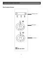
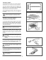
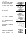
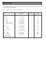
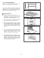
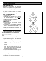
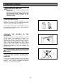
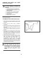
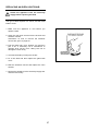
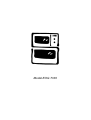
Model EOG 7330
IMPORTANT SAFETY INFORMATION
These warnings are provided in the interests of your safety. Ensure that you understand them all before installing
or using the appliance. Your safety is of paramount importance. If you are unsure about any of the meanings of
these warnings contact the Customer Care Department. The address is on the back page of this book.
INSTALLATION
Always use oven gloves to remove and place
food in the oven.
Never line any part of the appliance with foil.
Stand clear when opening the drop down oven
doors. Support the doors using the handles until
fully open.
Never leave the appliance unattended when
the oven door is open.
Do not place sealed cans or aerosols inside the
oven. They may explode if they are heated.
Ensure that all control knobs are in the OFF
position when not in use.
Do not stand on the appliance or on the open
oven doors.
Do not hang towels, dishcloths or clothes from
the appliance or its handles. They are a safety
hazard.
The appliance must be installed according to the
instructions supplied. The installation work must be
undertaken by a competent person as stated in the
Gas Safety (Installation & Use) Regulations current
edition.
The installer should check that the appliance is
suitable for the gas supply by checking the rating
plate.
The appliance must be installed in an adequately
ventilated room.
NOTE: It is imperative that the appliance is left in
the base to protect both the appliance and the floor.
This appliance is heavy and care must be taken
when moving it. Do not try to lift or move the
appliance by pulling the door handles.
Warning: Do Not attempt to lift this appliance by
the handles.
All packaging, both inside and outside the
appliance must be removed before the appliance is
used.
It is dangerous to alter the specifications or modify
the appliance in any way.
After installation please dispose of the packaging
with due regard for safety and the environment.
Your local authority can arrange this.
CLEANING AND MAINTENANCE
The appliance is heavy and care must be taken
when moving it.
For hygiene and safety reasons this
appliance should be kept clean at all times.
A build-up of fats or other foodstuffs could
result in a fire especially in the grill pan.
This appliance should be kept clean at all times.
A build-up of fats or other foodstuffs could result
in a fire, especially in the grill pan.
Do not leave cookware containing foodstuffs,
e.g. fat or oil in the appliance in case it is
inadvertently switched on.
Always allow the cooling fan to cool the
appliance down before switching off at the wall
prior to carrying out any cleaning / maintenance
work.
Only clean this appliance in accordance with the
instructions given in this book.
CHILD SAFETY
Do not allow young children to play with any part of
the packaging.
This appliance is designed to be operated by
adults. Young children must not be allowed to
tamper with the controls or play near or with the
appliance.
CAUTION: Accessible parts may be hot when
the grill is in use. Young children should be
kept away.
SERVICE
DURING USE
Repairs should not be carried out by
inexperienced persons as this may cause injury
or serious malfunction. This appliance should
be serviced by an authorised Service Engineer
and only genuine approved spare parts should
be used. Details of servicing and repair
arrangements are supplied on page 30 of this
book.
This appliance is not intended to be operated by
means of an external timer or separate remote
control system.
This appliance has been designed for domestic use
to cook edible foodstuffs only, and must not be
used for any other purposes.
Take great care when heating fats and oils as they
will ignite if they become too hot.
Never place plastic or any other material which may
melt in the oven.
Do not stand too close to the oven or grill while in
use as warm air will exhaust from the grill cavity
and the vents on the front frame of the appliance.
When lighting any burner check that it is lit before
leaving the appliance.
When turning off any burner do not leave the
appliance until the flame has gone out.
Do not leave the grill pan handle in position when
grilling and ensure oven gloves are used to remove
and replace the handle, as it will become hot.
AT THE END OF THE APPLIANCE'S LIFE
When the time comes to dispose of your
appliance please contact your local Council
Authority. They can arrange to dispose of the
appliance in a safe and controlled manner. The
number will be in the telephone book.
Please read the
instruction book carefully
before use and retain for
future reference.
2
CONTENTS
FOR THE USER
Important Safety Information
Description Of The Appliance
2
4
Getting To Know Your Oven
The Cooling Fan For The Controls
Location
5
6
6
Before Using The Appliance
Rating Plate
Connecting to the Electricity Supply
When First Switching On
Preparing to use your Appliance
Condensation And Steam
Cookware
Grill and Oven Furniture
7
7
7
7
8
8
8
9
The Electronic Timer
10
The Grill
Uses of the Grill
How To Light the Grill
To turn off the Grill Burner
Things To Note
The Grill Shelf
The Grill Pan and Handle
Hints And Tips
Grilling Chart
14
14
14
14
14
15
15
16
17
The Oven
Uses of the Oven
Preheating
How To Light the Oven
Things To Note
To turn off the Oven
To Fit The Oven Shelves
Hints And Tips
Roasting
18
18
18
18
18
18
19
19
20
Oven Cooking Chart
21
Slowcook Feature
Uses of Slowcook
How To Use Slowcook
Things to Note
Hints and Tips
22
22
22
22
22
Care and Cleaning
23
Cleaning Materials
23
Cleaning The Outside Of The Appliance
23
Cleaning the Control Knobs and Handles (Where
Applicable)
23
Cleaning The Outer and Inner Door
Glass Panels
24
To Remove the Outer Door Glass
24
To Replace the Outer Door Glass
25
To Clean the Inner Glass Door
25
Cleaning the Grill and Oven Compartments
25
To Remove the Wirework Runners
26
Cleaning the Shelves, Wirework Runners and
Grill/Oven Furniture
26
Cooking to Reduce Soilage
26
Replacing An Oven Light Bulb
27
Something Not Working
Service and Spare Parts
Guarantee Conditions
28
30
31
FOR THE INSTALLER
Technical Details
Things You Need to Know
Warnings
Things To Note
32
33
33
33
Getting Things Ready
34
Flexible Pipe Installation
35
Connection To Electricity Supply
36
Installation Between Cabinets
Checking the Electrical Connections
37
37
Pressure Testing
Checking the Grill
Checking the Oven
38
38
38
Please read the whole instruction book before using
the appliance. To help you the following symbols
will be found in the text.
Hints and Tips
Safety Instructions
3
DESCRIPTION OF THE APPLIANCE
Built in gas oven and grill
WARNING: THIS APPLIANCE MUST BE EARTHED AND PROTECTED BY A 3 AMP FUSE
Electronic Timer
Grill
Control Knob
Control Panel
Oven
Your built-in appliance comprises of a gas oven and grill.
The oven also features a Slowcook setting which allows you to cook a range of foods over a long period of time at
a low temperature.
The oven can be automatically controlled by the electronic timer.
4
GETTING TO KNOW YOUR OVEN
The Control Panel
Electronic Timer
Grill Control
Oven Control
5
THE
COOLING
CONTROLS
FAN
FOR
THE
Your appliance has a cooling fan fitted behind the
controls to prevent them from overheating.
The cooling fan will come on immediately when the
grill is switched on and after a short time when the
oven is in use.
The cooling fan may run on after the oven or grill is
turned off for a period of time to cool the appliance
down. It may continue to switch on and off until the
appliance is cool.
Always allow the cooling fan to cool the
appliance down before switching off at the
wall prior to carrying out any cleaning or
maintenance work.
NOTE
The action of the cooling fan will depend on how long
the oven or grill have been used and at what
temperature. It may not run on where the grill or
oven has only been used for a short time.
Do not stand to close to the grill or oven
when in use as warm air will exhaust from
the grill cavity and oven vents.
LOCATION
All gas ovens require adequate ventilation.
The room the oven is fitted in must have a
good air supply that meets the standard BS
5440 Part 2 (current edition). Your installer
will tell you if you not sure.
The oven may be placed in a kitchen,
kitchen/diner or bedsit but not in a
bathroom or shower room. It should not be
installed in a bedsit smaller than 20m³.
L.P.G. cookers MUST NOT be installed
below ground level, i.e. in a basement, or
aboard any boat, yacht or other vessel.
The use of a gas cooking appliance results in the
production of heat and moisture in the room in which
it is installed.
Ensure that the kitchen is well
ventilated: keep natural ventilation holes open or
install a mechanical ventilation device (mechanical
extractor hood).
Prolonged intensive use of the appliance may call for
additional ventilation, for example opening of a
window, or more effective ventilation, for example
increasing the level of mechanical ventilation where
present.
6
BEFORE USING THE APPLIANCE
RATING PLATE
This is situated on the lower front frame of the
appliance upon opening the door. Alternatively the
rating plate may also be found on the back or top of
some models (where applicable).
The appliance must be protected by a suitably rated
fuse or circuit breaker. The rating of the appliance is
given on the rating plate.
Do not remove the rating plate from the appliance
as this may invalidate the guarantee.
CONNECTING
SUPPLY
TO
THE
ELECTRICITY
This appliance must be earthed and
protected by a 3 amp fuse.
The plug supplied with the oven can be fitted directly
to a suitable three pin earthed socket. Ensure the
plug is accessible to the user.
If you have to change the fuse replace it with a 3 amp
fuse which has been ASTA approved to BS 1362.
Do not use the plug until you have put the fuse cover
back on. If you cut the plug off dispose of it safely as
it will be a shock hazard if it is inserted into a 13 amp
socket elsewhere in the house.
If the ignition system doesn’t work there may be a
fault with the electrical supply. First, check the
socket by trying out another piece of electrical
equipment in it, if that works correctly renew the fuse
in the plug.
If the fuse keeps failing there is a fault in the oven
which must be put right. Do not use a fuse with a
rating higher than 3 amps. Do not carry out other
electrical work. Unplug the oven and tell your
installer.
WHEN FIRST SWITCHING ON
The timer must be set to manual operation before the
oven can be operated. This must be done whenever
the appliance is switched off at the wall or when there
has been a power failure. For instructions on how to
set the timer see page 10.
The grill is not controlled by the electronic timer.
7
PREPARING TO USE YOUR APPLIANCE
Wipe over the grill compartment and oven base with
a soft cloth and some hot soapy water and wash the
grill and oven furniture before use.
The grill and oven should be heated without food to
burn off any residue from the grill and oven surfaces.
To do this run the oven at Gas Mark 7 for
approximately 10 - 15 minutes.
The procedure should be repeated with the grill for
approximately 5 – 10 minutes.
During this period and unpleasant odour may be
emitted, it is therefore advisable to open a window for
ventilation.
CONDENSATION AND STEAM
When food is heated it produces steam in the same
way as a boiling kettle does. The oven is vented to
allow some of this steam to escape. However,
always stand back from the appliance when opening
the oven door to allow any build up of steam or heat
to be release. If the steam comes into contact with a
cool surface on the outside of the appliance, e.g. a
trim, it will condense and produce water droplets.
This is quite normal and is not caused by a fault on
the appliance.
To prevent discolouration occurring, regularly wipe
away condensation and any soilage from the
appliance surfaces.
COOKWARE
Baking trays, oven dishes etc., should not be placed
over the oven burner. This will damage the oven as
well as the ovenware.
Do not use baking trays larger than 30cm x 30cm
(12” x 12”) as they will restrict the circulation of heat
and may affect performance.
Advice on the effect of different materials and
finishes of bakeware is given in ‘Hints and Tips’ in the
appropriate oven section.
8
GRILL AND OVEN FURNITURE
The following items of oven furniture have been
supplied with the appliance.
1 grill pan
1 grill pan handle
1 grill pan grid
1 meat tin
1 shelf for grilling
2 shelves for
Oven cooking
9
THE ELECTRONIC TIMER
KEY
A
B
C
D
E
F
G
COOK TIME
END TIME
COUNTDOWN
TIME OF DAY
DECREASE CONTROL
SELECTOR CONTROL
INCREASE CONTROL
A
C
B
D
E
NOTE:
The time of day must be set before the oven will
operate manually.
1. HOW TO SET THE TIME OF DAY
The oven has a 24 hour clock.
When the electricity supply is first switched ON, the
display will show 12.00 and the 'Time Of Day'
indicator neon will flash as Fig. 1.
Fig.1
To set the correct time press the increase control
button (+) and if necessary, the decrease control
button (-) until the correct time on the 24 hour clock is
reached, e.g. 10.00am as Fig. 2. The 'Time Of Day'
indicator neon will flash for 5 seconds and then go
out.
NOTE:
The increase and decrease control
buttons operate slowly at first, and then more
rapidly. They should be pressed separately.
Fig.2
2. HOW TO SET THE COUNTDOWN
The 'Countdown' gives an audible reminder at the
end of any period of cooking. This cooking period
may be up to 2 hrs 30 mins. It is not part of the
automatic control.
To set, press the Selector Control button until the
'Countdown' indicator neon is illuminated and the
display reads 0.00 as Fig. 3.
To set the correct time duration depress the increase
control (+) until the display indicates the interval to be
timed, e.g. 1hr 45 mins as Fig. 4. If necessary
depress the decrease control (-) to achieve the
correct time interval.
Fig.3
NOTE: This must be completed within 5 seconds
of first pressing the Selector Control button.
During the operation of the 'Countdown', the
remaining time period will be shown in the display.
The 'Countdown' will sound intermittently for up to 2
minutes at the end of the timed period. The sound
can be stopped by pressing any button.
Fig.4
10
F
G
TO CANCEL THE COUNTDOWN
If you change your mind and want to cancel the
'Countdown', press the Selector Control button until
the 'Countdown' indicator neon flashes then depress
the decrease control (-) until 0. 00 shows in the
display as Fig. 5. The 'Countdown' indicator neon
will continue to flash for a few seconds and then
return to the time of day.
Fig.5
3. SETTING THE OVEN TIMER CONTROL
The oven only can be automatically timed.
When using the timer control for the very first time, it
is advisable to let it operate while you are at home.
The displays can be checked to show that it is
operating correctly and you will feel confident to
leave a meal to cook automatically in the future.
A) TO SET THE TIMER TO SWITCH ON
AND OFF AUTOMATICALLY
i) Ensure the electricity supply is switched ON and
that the correct time of day is displayed, e.g.
9.a.m. as Fig. 6.
ii) Place food in oven.
iii) To set the length of cooking time. Press the
Selector Control button until the 'Cook Time'
indicator neon is illuminated. Press the increase
control (+) until the required length of cooking time
is displayed, e.g. 2 hrs 15 mins as Fig. 7. If
necessary depress the decrease control (-) until
the correct time interval is achieved.
The maximum cooking time is 10 hours.
iv) Release the buttons. The 'Cook Time' indicator
neon will be illuminated.
Fig.6
Remember, this must be completed within 5
seconds of first pressing the Selector Control
button.
v) To set the 'End Time'. Press the Selector Control
button until the 'End Time' indicator neon flashes.
Press the increase control button (+) until the
required stop time is displayed, e.g. 12.15 p.m. as
Fig. 8. If necessary depress the decrease control
(-) until the correct time interval is achieved.
vi) Release the buttons. The time of day will be
displayed after 5 seconds. The 'Cook Time' and
'End Time' indicator neons will be illuminated.
The 'End Time' must not be more than 23 hours
59 minutes from the time of day. For example, if
the time of day is 09.00 a.m., the latest 'End Time'
would be 08.59 a.m. the next day.
vii) Set the oven control to the required temperature.
The oven indicator neon should be OFF.
Fig.7
Fig.8
NOTE: When the automatic timed period starts,
the oven indicator neon will turn ON and OFF
periodically during cooking, showing that the
temperature is being maintained.
11
B)
TO SET THE TIMER TO SWITCH OFF
ONLY
i)
ii)
iii)
iv)
v)
vi)
Ensure the electricity supply is switched
ON and that the correct time is
displayed, e.g. 10.00 a.m. as Fig. 9.
Place food in oven.
To set the length of cooking time, press
the Selector Control button until the
'Cook Time' indicator is illuminated.
Press the increase control button (+) until
the required length of cooking time is
displayed, e.g. 2 hrs 15 mins as Fig. 10.
Depress the decrease control button (-) if
necessary.
Release the buttons. The 'Cook Time'
indicator neon will be illuminated and the
time of day will be displayed after 5
seconds.
Set the oven temperature. The oven
indicator neon should be ON.
To check the 'End Time' during the
cooking period, simply press the Selector
Control button once and the remaining
time will be displayed, as Fig. 11.
4. TO
CANCEL
PROGRAMME
i)
ii)
iii)
AN
Fig.9
Fig.10
Fig.11
AUTOMATIC
To cancel an automatic programme
press the Selector Control button until
the 'Cook Time' indicator neon flashes.
Press the decrease control until the
display reads 0.00 as Fig. 12.
Release the buttons. The 'Cook time'
indicator will flash and after 5 seconds
return to the time of day.
Turn off oven control.
Fig.12
5. TO RETURN THE APPLIANCE TO
MANUAL
At the end of a timed cooking period, the indicator
neon will flash and an alarm will sound for up to 2
minutes.
i)
To stop the sound press any of the three
buttons, as Fig. 13.
ii)
The display will return to the time of day.
iii)
Turn off the oven controls.
Fig.13
12
6. THINGS TO NOTE
In the event of an interruption of the electricity
supply, the timer will reset itself to zero, and all
programming will be cancelled.
7. AUTOMATIC COOKING
It is advisable to leave food in the oven for as
short a time as possible before automatic
cooking. Always ensure commercially prepared
food is well within its use by date and that home
prepared food is fresh and of good quality.
When cooking is complete, do not leave food to
stand in the oven, but remove and cool it quickly
if the food is not to be consumed immediately.
Always ensure food in the oven has been
covered before cooking if it is not possible to
remove food immediately after cooking.
13
THE GRILL
WARNING – Accessible parts become hot
when the grill is in use. Keep children
away.
USES OF THE GRILL
The grill is situated in the top compartment.
The grill gives variable heat settings. Use the high
setting for foods that cook quickly such as toast and
the lower setting to cook thicker foods such as
chicken after it has been browned on the high setting.
HOW TO LIGHT THE GRILL
1. Open the Grill door.
2. Push in the grill control and turn it anticlockwise to
the highest setting. This is shown by a large
flame symbol.
3. Adjust the setting as required.
4. Place grill pan with food under the grill.
The grill door must be left open when
grilling.
Check that the grill burner is lit before you
leave the appliance.
Never cover the grill pan or grid with foil as
this can lead to grill fires.
TO TURN OFF THE GRILL BURNER
1. Push in the control knob and turn it to the OFF
position. This is shown by a large dot.
THINGS TO NOTE
·
The cooling fan for the controls will operate as
soon as the grill control is turned. For more
information on the operation of the cooling fan
turn to page 6.
·
If the oven door is closed whilst the grill burner is
lit, it will go out. The burner will automatically relight when the door is opened.
·
Always light the burner before placing food
under the grill.
14
THE GRILL SHELF
The grill shelf can be used in one of three positions.
Shelf positions are counted from the top downwards.
1
The shelf should be fitted with the straight rods
uppermost on the frame and the forms towards the
back of the oven. If not fitted correctly the anti-tilt
and safety stop mechanism will be affected.
2
3
When using the grill in position 2 and 3 the shelf must
be withdrawn before the pan can be located or
removed.
Ensure the grill pan is properly located.
THE GRILL PAN AND HANDLE
The grill pan has a removable handle.
To insert the handle, press the button on the handle
with the thumb and pivot the handle slightly upwards
inserting the lip into the widest part of the bracket.
Move the handle towards the left, lower into position
and release the button.
Ensure the handle is positively located.
To remove the handle, press the button on the
handle with the thumb and pivot the handle slightly
upwards and towards the right to remove from the
bracket.
Protect your hands when removing the grill
pan handle.
Always remove the grill pan handle during
grilling.
To correctly locate the grill pan on the shelf, ensure
that the cut out on the underside of the handle
bracket locates over the front bar of the shelf.
The Grill Pan must not be located in the
shelf runners.
To check the progress of the food being grilled, the
grill pan should be withdrawn on the shelf to attend to
food during cooking.
Ensure that the grill pan is supported when
it is withdrawn.
15
HINTS AND TIPS
·
Most foods should be placed on the grilling grid
in the grill pan. This allows maximum circulation
of air by raising the food out of fats and juices.
·
The grilling grid is reversible. Adjust the grid
height and grill pan runner position to allow for
different thicknesses of food. Position the food
close to the burner for faster cooking and further
away for more gentle cooking.
·
Food should be thoroughly dried before grilling to
minimise splashing. Brush lean meats and fish
lightly with a little oil or melted butter to keep
them moist during cooking.
·
The food should be turned over during cooking
as required. Do not use the grill to keep food
warm as it will continue to cook the food.
·
The grill door must be left open when grilling.
For convenience the grill door can be left ajar.
·
You may wish to preheat the grill on full setting
for a few minutes before sealing steaks or
browning food.
·
The grill compartment can be used to warm
plates when the oven is on. Do not place plates
to warm under the grill when it is lit as this may
damage the plates.
·
Place food towards the centre of the grilling grid.
If food is outside this area it may require rotating
during cooking. Food such as tomatoes and
mushrooms requiring gentle heat should be
placed towards the edge of the grid.
·
Place foods such as Shepherd's pie and
cauliflower cheese on the grill shelf to brown.
16
GRILLING CHART
The chart below gives recommended cooking times and shelf positions. Remember that these are a guide and
should be adjusted to suit personal taste.
Note: Shelf positions are counted from the top downwards.
FOOD
GRILL TIME
(Min)
SHELF
GRID
POSITION
Bacon Rashers
2 – 3 each side
1
High
Beefburgers
6 – 10 each side
1
Low
Chicken Joints
15 – 20 each side
2
High
Chops - Lamb
Pork
7 – 10 each side
10 – 15 each side
1
1
Low
Low
Fish –
8 – 12 each side
4 – 6 each side
1
1
Low
Low
Kebabs
10 – 15 each side
1
Low
Kidneys – Lamb
Pig
4 – 6 each side
8 – 10 each side
1
1
Low
Low
Liver –
5 – 10 each side
1
Low
10 –15 turn as required
1
Low
3 – 6 each side
6 – 8 each side
7 – 10 each side
1
1
1
High
High
High
3 – 5 mins
2
-
Whole / Herring
Fillets – Plaice / Cod
Lamb/Pig
Sausages
Steaks -
Rare
Medium
Well Done
Browning e.g. au gratin,
Lasagne, Shepherd’s Pie
17
THE OVEN
USES OF THE OVEN
The oven is ideal for baking, roasting and casseroles.
The oven also includes a Slowcook feature.
It is important to refer to the oven cooking chart as a
guide to shelf positions and gas mark settings as
these may differ from previous appliances you may
have used.
PREHEATING
It is not necessary to preheat the oven for
casseroles.
For recipes needing high temperatures such as
bread, pastries, scones, soufflés etc. best results are
achieved if the oven is preheated for 20 minutes.
When cooking or reheating frozen or chilled food
read the instructions on the packaging.
HOW TO LIGHT THE OVEN
1. Open the oven door.
2. Push in the oven control and turn it to gas mark
9.
3. Adjust the control to the required gas mark
setting.
4. Wait until the burner has a large flame.
5. Close the oven door.
THINGS TO NOTE
·
The oven light will come on when the oven
control is turned.
·
The cooling fan for the controls may operate after
a time. See page 6 for further details on the
operation of the cooling fan.
·
If an automatic programme has been set, the
oven light does not come on until the cook time
begins.
Do not place cookware over the oven
burner. This will damage the oven and
ovenware.
TO TURN OFF THE OVEN
1. Push in the control knob and turn it to the Off
position. This is shown by a large dot.
18
TO FIT THE OVEN SHELVES
There are 14 shelf positions in the oven. Shelf
positions are counted from the top downwards.
1
The shelves should be fitted with the straight rods
uppermost on the frame and the forms towards the
back of the oven. If not fitted correctly the anti-tilt
and safety stop mechanism will be affected.
14
HINTS AND TIPS
·
There are zones of heat within the oven. The
temperature in the middle is the gas mark you
have chosen. The top of the oven is slightly
hotter and the lower shelf slightly cooler.
·
Use the heat zones when cooking foods requiring
different temperatures all at the same time.
·
When cooking more than one tray of similar
items, for example cakes or biscuits, swap the
trays round during cooking. Alternatively remove
the top tray when the food is cooked and move
the lower tray to the higher shelf to finish
cooking.
·
It is recommended that when baking larger
quantities, the shelf positions should be evenly
spaced to suit the load being cooked. A slight
increase in cooking time may be necessary.
·
The material and finish of the baking tray and
dishes will affect the degree of base browning of
the food. Enamelware, dark, heavy or non-stick
utensils increase base browning. Shiny
aluminium or polished steel trays reflect the heat
away and give less base browning.
19
·
For economy leave the door open for the shortest
possible time, particularly when placing food into
a pre-heated oven.
ROASTING
For best results we recommend open roasting using
minimal fat or oil to prevent splashing.
It is not necessary to cover meat or poultry or wrap
food in foil when roasting as this restricts the
circulation of heat and will lead to extended
cooktimes.
If you are using a roasting bag or cover chicken
breast with foil, be prepared to allow an extra 10 – 15
minutes for each 1/2kg (1Ib).
When cooking large items such as turkeys, the use of
foil may be required to prevent the breast becoming
dry before the rest of the bird is fully cooked.
20
OVEN COOKING CHART
The Gas mark settings are intended as a guide only. It may be necessary to increase or decrease the settings to
suit individual preferences and requirements.
Note: Shelf positions are counted from the top and the oven downwards.
SHELF
POSITION
GAS MARK SETTING
Viennese Biscuits
Bread
Bread Rolls / Buns
Cakes:
Small & Queen
Sponges
Victoria Sandwich
Madeira
Rich Fruit
Christmas
Gingerbread
Flapjack
Shortbread
Baked Custard
Casseroles:
Beef / Lamb
Chicken
Convenience Foods
7
10
10
5 & 11
5 & 11
5 & 11
7
9
10
8
7
7
10
10
10
7
Fish
Fish Pie - Potato Topped
Fruit Pies
Crumbles
Milk Puddings
Pasta / Lasagne etc.
Pastry :
Choux – Eclairs/Profiteroles
7
8
4 & 10
6
10
7
5
7
7
7
5
5
4
4
2
2
2
5
2
3
3
4
According to manufacturers
instructions
5
7
6
5
2
5
4
7
7
4
5 & 11
7
9
14
5 & 11
8
7
7
10
5
5
7
6
5
6
5
5
5
7
7
5
5
6
7
7
FOOD
Roasting Meat /
Turkey
Scones
Shepherd’s Pie
Soufflés
Vegetables:
Flaky / Puff Pies
Shortcrust
Mince Pies
Meat Pies
Quiche, Tarts, Flans
Poultry
Baked Jacket Potatoes
Roast Potatoes
Yorkshire Puddings: - Large
Individual
21
SLOWCOOK FEATURE
USES OF SLOWCOOK
Slowcooking in the oven allows most foods to be
cooked at a low temperature over a number of hours.
A variety of foods, particularly cheaper cuts of meat
can be cooked in this way making them tender, tasty
and succulent.
This feature is most convenient when used in
conjunction with the automatic timer as there is no
need to be present at the start of cooking.
HOW TO USE SLOWCOOK
1. Open the oven door.
2. Push in the oven control and turn it to gas mark
9. When the burner has lit there will only be
small flames at first.
3. Turn the control to the Slowcook setting. S
4. Wait until the burner has a large flame.
5. Close the oven door.
THINGS TO NOTE
·
The oven light will come on when the oven
control is turned.
·
The cooling fan for the controls may operate after
a time. See page 6 for further details on the
operation of the cooling fan.
·
If an automatic programme has been set, the
oven light does not come on until the cook time
begins.
Do not place cookware over the oven burner.
This will damage the oven and ovenware.
HINTS AND TIPS
·
·
·
Always cover food with a close fitting lid or tin foil.
·
It is recommended that vegetable dishes, sponge
and suet puddings are prepared just prior to
cooking.
·
A complete meal can be cooked using slow cook
function.
·
Most foods should be cooked on the middle
shelf. Use shelf position 9 for large joints and
stews. Ensure dishes are evenly spaced to allow
for maximum circulation around food.
·
Thicken casseroles by tossing meat in flour first
or by blending flour with water and adding at the
end.
·
Pastries, breads and biscuits are not suitable for
slow cooking.
·
·
Adjust seasoning at the end of the cook time.
Do not re-heat food using the slow cook function.
Slow cooked food should be eaten as soon as
possible after cooking. It is not advisable to allow
food to cool down slowly.
Thaw frozen foods thoroughly before cooking.
22
CARE AND CLEANING
For hygiene and safety reasons this gas
appliance must be kept clean.
A build up of fat or other foodstuffs could
cause a fire.
Before cleaning the appliance always allow
the cooling fan for the controls to cool the
appliance down before switching off the
electricity supply.
CLEANING MATERIALS
Before using any cleaning materials on your
appliance, check that they are suitable and that their
use is recommended by the manufacturer.
Cleaners that contain bleach should NOT be used as
they may dull the surface finishes. Harsh abrasives
should also be avoided.
CLEANING THE
APPLIANCE
OUTSIDE
OF
THE
DO NOT use abrasive cleaning materials or scourers
on the outside of the appliance as some of the
finishes are painted and damage may occur.
Regularly wipe over the control panel and oven doors
using a soft cloth well wrung out in warm water to
which a little liquid detergent has been added.
Stainless Steel cream cleaners are abrasive and
should be avoided as they may damage the
surface finish.
Do not attempt to remove any of the control
knobs from the appliance as this may cause
damage.
CLEANING THE CONTROL KNOBS AND
HANDLES
It is strongly recommended that only hot soapy water
is used for cleaning the control knobs and door
handles. ANY OTHER CLEANING MATERIALS
WILL DULL THE SURFACE FINISH.
23
CLEANING THE OUTER AND INNER
DOOR GLASS PANELS
To prevent damaging or weakening the
door glass panels avoid the use of the
following:
·
Household detergents and bleaches
·
Impregnated pads unsuitable for nonstick saucepans
·
Brillo/Ajax pads or steel wool pads
·
Chemical oven pads or aerosols
·
Rust removers
·
Bath/Sink stain removers
The outer grill and oven door glass panels are
removable for cleaning.
TO REMOVE THE OUTER DOOR GLASS
1. Open the grill or oven door slightly to gain access
to the two cross head screws on the top of the
oven door.
2. Loosen the
screwdriver.
two screws
using a Pozidrive
3. Holding the door glass securely in place with one
hand remove the screws and washers with the
other hand.
The screws and washers retain the trim on the top
of the grill door. Note the position of the trim on
the door.
4. Holding the door and glass with one hand, gently
pull towards you and slightly lift the door glass
with the other hand to disengage the panel from
the location point at the bottom of the door.
Gently release the door to close it.
5. Clean the outer and inner glass using hot soapy
water or Hob Brite. Should the inner face of the
outer door glass be heavily soiled it is
recommended that soapy water with a high
concentration of soap is used.
To prevent
streaking, a glass cleaning spray may be applied
and the glass polished with a soft cloth. Ensure
that all parts are thoroughly dry before attempting
to replace the outer door glass.
If the door glass panel becomes chipped or
has deep scratches the glass will be
weakened and must be replaced to prevent
the possibility of the panel shattering.
Please contact your local Service Force
Centre who will be pleased to advise
further.
24
TO REPLACE THE OUTER DOOR GLASS
1. Holding the door glass panel with both hands,
gently place the locators into the holes of the
brackets at the bottom of the oven door.
2. Holding the door glass with your left hand, use
your right hand to open the oven door.
Bring the door gently towards the glass panel
ensuring the screw location holes line up.
3. Place the trim in the correct position on the top of
the grill door.
4. Hold the glass in place with one hand and insert
the cross head screws with washers into the
location holes with the other hand. Give the
screws one turn to ensure the glass is secure.
5. Tighten the screws positively with a Pozidrive
screwdriver before closing the oven door.
DO NOT attempt to use the oven without the
glass being in place.
TO CLEAN THE INNER GLASS DOOR
The inner glass door is not removable. Clean using
hot soapy water or Hob Brite and a soft cloth. DO
NOT use abrasives as they may damage the glass or
seal.
CLEANING INSIDE THE GRILL AND OVEN
COMPARTMENTS
The vitreous enamel coating in the grill compartment
and main oven compartment can be cleaned using
normal oven cleaners or aerosol oven cleaners with
care. Ensure that the manufacturers instructions are
followed and that all parts are well rinsed afterwards.
Aerosol cleaners must not come into contact with
elements or the door seal as this may cause
damage.
25
TO REMOVE THE WIREWORK RUNNERS
The wirework runners in the grill and oven can be
removed for cleaning.
1. Remove all shelves and furniture from the grill /
oven compartments.
SIDE PANEL
2. Hold the wirework at the bottom and gently pull
towards the centre of the grill or oven
compartment.
CAVITY CENTRE
3. Unhook the runner at the top and remove it from
the cavity.
4. To replace, hook the wirework back into the oven
sides.
Ensure that the wirework runners are
firmly in place before refitting the shelves.
CLEANING THE SHELVES, WIREWORK
RUNNERS AND GRILL/OVEN FURNITURE
All removable parts, except the grill pan handle, can
be washed in the dishwasher.
The meat tin, grill pan, grill pan grid, oven shelves
and wirework runners may be cleaned using a soap
impregnated steel wool pad. Soaking first in hot
soapy water will make cleaning easier.
COOKING TO REDUCE SOILAGE
·
Cook at the recommended temperatures. Higher
temperatures during roasting will increase
soilage. Try cooking at lower temperatures for
an increased length of time, you will save energy
and often the joint is more tender.
·
Use minimal, if any, extra oil or fat when roasting
meat, potatoes only require brushing with fat
before cooking. Extra fat in the oven during
roasting will increase splashing and soilage.
·
It is NOT necessary to add water to a meat tin
when roasting. The water and the fat juices from
the joint create excessive splattering during
cooking – even at normal temperatures, as well
as causing condensation.
·
Covering joints during cooking will also prevent
splashing onto the interior surfaces. Removing
the covering for the last 20-30 minutes will allow
extra browning if required. Some large joints and
turkeys especially benefit by this method of
cooking, allowing the joint to cook through before
the outside is over-browned.
26
REPLACING AN OVEN LIGHT BULB
Isolate the appliance from the electricity
supply before replacing the bulb.
The type of bulb required is a 300°C, 25 watt small
Edison Screw.
1. Make sure the appliance is cool before you
replace a bulb
2. Open the oven door and remove the shelves and
wirework runners.
Instructions on how to remove the wirework
runners are given on page 26.
3. Pull the glass bulb cover towards you and then
pull it off. If necessary use a screwdriver to
carefully lever off the cover, taking care not to
damage the oven cavity.
4. Unscrew the bulb by turning it to the left.
5. Fit a new bulb and then replace the glass bulb
cover.
6. Refit the wirework runners and replace the oven
shelves.
7. Restore the appliance to the electricity supply and
reset the time of day.
27
SOMETHING NOT WORKING
Please carry out the following checks on your appliance before calling a Service Engineer. It may be that the
problem is a simple one which you can solve yourself without the expense of a service call.
If our Service Engineer finds that the problem is listed below you will be charged for the call whether or not the
appliance is under guarantee.
PROBLEM
The grill, oven and timer do not work.
POSSIBLE SOLUTION
Check that the appliance is switched on at the wall.
Check that there has not been a power failure. If the
electricity supply has been interrupted or you have
switched the oven off at the wall, the grill may have cut
out before the cooling fan has cooled the appliance
down. Switch the appliance on at the wall until the
cooling fan has cooled it down.
Check that there is not a problem with your gas supply.
You can do this by making sure that other gas
appliances such as your central heating or gas fire are
working.
The Grill works but the Oven does not
Check that the timer is set for manual operation. See
page 10.
The Grill sparks in use
Ensure that the grill door is open when grilling. If the
grill door is closed whilst the burner is lit it will
automatically re-light when the door is opened.
Always light the burner before placing the grill pan and
food under the grill.
The Grill does not work
Ensure the cooling fan is running when the grill is on. If
the cooling fan fails, the grill will not work.
Contact your nearest local Service Force Centre.
The timer does not work.
Check that the instructions for the operation of the timer
are being closely followed.
The oven or grill burner flame is unstable / noisy
Check that the burner flames stabilise after a few
minutes. The appliance may need to adjust to room
temperature
The oven is not cooking evenly.
Check that the appliance is correctly installed and is
level.
Check that the recommended Gas mark settings and
shelf positions are being used.
28
The oven light fails to illuminate.
The oven light bulb may need replacing, see page 27.
If the Oven is set for automatic cooking the light will
illuminate when the cook time begins.
Food is cooking too quickly or too slowly
Check that the recommended Gas mark settings and
shelf positions are being used. See page 21. Be
prepared to adjust the gas mark up or down by one
setting to achieve the results you want.
29
SERVICE AND SPARE PARTS
In the event of your appliance requiring service, or if you wish to purchase spare parts, please contact your local
Service Force Centre by telephoning:-
0870 5 929929
Your telephone call will be automatically routed to the Service Force Centre covering your post code area.
For the address of your local Service Force Centre and further information about Service Force, please visit the
website at www.serviceforce.co.uk
Before calling out an engineer, please ensure you have read the details under the heading "Something Not
Working".
When you contact the Service Force Centre you will need to give the following details:
1. Your name, address and post code.
2. Your telephone number.
3. Clear and concise details of the fault.
4. The model and serial number of the appliance (found on the rating plate).
5. The purchase date.
Please note that a valid purchase receipt or guarantee documentation is required for in-guarantee service
calls.
CUSTOMER CARE DEPARTMENT
For general enquires concerning your Electrolux appliance, or for further information on Electrolux products, please
contact our Customer Care Department by letter or telephone at the address below or visit our website at
www.electrolux.co.uk
Customer Care Department
Electrolux
55 – 77 High Street
Slough
Berkshire
SL1 1DZ
Tel: 0870 5 950950 (*)
*calls to this number may be recorded for training purposes.
30
GUARANTEE CONDITIONS
Standard guarantee conditions
We, Electrolux, undertake that if within 12 months of the date of the purchase this Electrolux appliance or any part
thereof is proved to be defective by reason only of faulty workmanship or materials, we will, at our option repair or
replace the same FREE OF CHARGE for labour, materials or carriage on condition that:
·
·
The appliance has been correctly installed and used only on the electricity supply stated on the rating plate.
·
The appliance has not been serviced, maintained, repaired, taken apart or tampered with by any person not
authorised by us.
·
·
·
All service work under this guarantee must be undertaken by a Service Force Centre.
The appliance has been used for normal domestic purposes only, and in accordance with the manufacturer’s
instructions.
Any appliance or defective part replaced shall become the Company’s property.
This guarantee is in addition to your statutory and other legal rights.
Home visits are made between 8.30am and 5.30pm Monday to Friday. Visits may be available outside these
hours in which case a premium will be charged.
Exclusions
This guarantee does not cover:
·
Damage or calls resulting from transportation, improper use or neglect, the replacement of any light bulbs or
removable parts of glass or plastic.
·
Costs incurred for calls to put right an appliance which is improperly installed or calls to appliances outside the
United Kingdom.
·
Appliances found to be in use within a commercial environment, plus those which are subject to rental
agreements.
·
Products of Electrolux manufacture which are not marketed by Electrolux.
European Guarantee
If you should move to another country within Europe then your guarantee moves with you to your new home
subject to the following qualifications:
·
·
The guarantee starts from the date you first purchased your product.
·
·
·
This guarantee relates to you and cannot be transferred to another user.
·
The product is installed taking into account regulations in your new country.
The guarantee is for the same period and to the same extent for labour and parts as exists in the new country
of use for this brand or range of products.
Your new home is within the European Community (EC) or European Free Trade Area.
The product is installed and used in accordance with our instructions and is only used domestically, i.e. a
normal household.
Before you move please contact your nearest Customer Care centre, listed below, to give them details of your new
home. They will then ensure that the local Service Organisation is aware of your move and able to look after you
and your appliances.
France
Germany
Italy
Sweden
UK
Senlis
Nürnberg
Pordernone
Stockholm
Slough
+33 (0) 3 44 62 20 13
+49 (0) 800 234 7378
+39 (0) 800117511
+46 (0) 20 78 77 50
+44 (0) 1753 219898
31
TECHNICAL DETAILS
Loading info :
Grill Burner
Natural gas
L.P. Gas
Heat Input
Injector Marking
2.8 kW ( 9554 Btu/h )
123
2.8 kW ( 201 g/h )
089
Heat Input
Injector Marking
Thermostat By-Pass Marking
1.7kW (5800 Btu/h)
095
74
1.7kW (122g/h)
060
79
Oven Light:
0.05kW
Control Cooling Fan
0.020kW
Timer:
0.005kW
Height:
Appliance 760 mm
Width:
593 mm
Depth:
(excluding handles and knobs)
550 mm
Weight:
52 Kg
Connection: Gas
Rear top right hand side of appliance Rc½ (½”P. Female)
Connection: Electric
230 - 240 Volt A.C. 50Hz Mains 3 core cable and moulded plug
fused to 3 amps.
GAS CATEGORY
COUNTRIES OF DESTINATION
Oven
CAT. I2H
GB, IE
CAT. I3+
GB, IE
Installed 720mm
IMPORTANT – SAFETY REQUIREMENTS
This appliance must be installed in accordance with the Gas Safety (Installation and Use) Regulations Current
Editions. Detailed recommendations are contained in the following British Standard Codes of Practice – BS.6172,
BS.5440: Part 2 and B.S.6891. All British Standards must be ‘Current Editions’.
PROVISION FOR VENTILATION
This appliance is not connected to a combustion products evacuation device. It shall be installed and connected in
accordance with the current installation regulations. Particular attention shall be given to the relevant requirements
regarding ventilation.
The room containing the appliance should have an air supply in accordance with BS.5440: Part 2 Current Edition.
All rooms require an openable window or equivalent and some rooms will require a permanent vent as well. For
3
2
3
3
room volumes up to 5m an air vent of 100cm is required: for room volumes between 5m and 10m an air vent of
2
50cm is required. If the room has a door that opens directly to the outside, no air vent is required. For room
3
volumes that exceed 11m no air vent is required. If there are other fuel burning appliances in the same room,
BS.5440: Part 2 Current Edition should be consulted to determine the requisite air vent requirements.
Prolonged intensive use of the appliance may call for additional ventilation, for example opening a window, or more
effective ventilation, for example increasing the level of mechanical ventilation where present.
32
INSTALLATION INSTRUCTIONS
NOTES
THINGS YOU NEED TO KNOW
WARNINGS:
·
In the interest of safety this appliance must be
installed and / or serviced by a competent person
(Corgi registered).
Safety may be impaired if
installation is not carried out in accordance with
these instructions.
·
·
This appliance must be earthed.
·
Before connected the appliance make sure that the
gas type and the voltage of your electricity supply is
the same as that indicated on the rating plate. The
rating plate can be seen on the rear panel of the
appliance.
·
Do not remove the screws from the earth tab
extending from the oven mains terminal block (Fig.
1).
Fig.1
Do not alter the electrical circuitry of this appliance.
NOTE: HOUSE CIRCUIT
Earth leakage / continuity tests must be carried out
before the appliance is connected to the mains supply
and re-checked after fitting.
NOTE: It is good practice to:
·
Fit an Earth Leakage Circuit Breaker to your house
wiring.
·
Wire your appliance to the latest IEE regulations.
Fig.2
THINGS TO NOTE
LOCATION OF APPLIANCE
The appliance may be located in a kitchen, a
kitchen/diner or bedsitting room, but not located in a
bathroom or shower room.
L.P.G. appliances MUST NOT be installed below ground
level i.e. in a basement or aboard any boat, yacht or
other vessel.
It is essential that there is a minimum clearance of
2mm between the top surface of the appliance and
the inside top of the cabinet.
·
This appliance is designed to be fitted between
cabinets with the recommended dimensions as
shown in Figs. 2 and 3.
33
Fig.3
INSTALLATION INSTRUCTIONS
NOTES
·
This appliance must not be installed on a wooden
base.
·
The dimensions given provide adequate air
circulation around the unit within the cabinet,
ensuring compliance with BS EN30.
Fig.4
GETTING THINGS READY
PREPARING CABINET FOR FITTING OVEN
·
Make sure the cabinet is the correct size for the
appliance to be fitted (Ref. Fig. 4).
·
If the size is between 605-610mm, then the cabinet
should be modified so that at the screw fixing points
the recommended dimension of at least 600-605mm
is maintained. The modification should ideally be
localised to ensure that after screw fitment the oven
is securely fixed into position.
·
The adjacent cabinets must be stable and firmly
secured to the wall or floor. If necessary, make
arrangements to ensure the work surface below
which the oven will rest is level.
·
Mark the centre of the aperture into which the
appliance is to be fitted onto the plinth board.
·
Remove the plinth board from in front of the
cabinets.
·
Cut the required ventilation slot in the plinth as
detailed in Fig.5.
·
Drill two pilot screw holes into the sides of the
adjacent cabinets, in the position indicated by Fig. 4.
·
Fit the appliance mounting brackets using the two
holes indicated in Fig. 6 to the adjacent cabinets
(Ref. Fig.4 & 7).
·
Check that the mounting brackets are level. They
can be adjusted if necessary by using the extra
holes at the ends of the brackets. Once the
brackets are level, drill a pilot hole through the
central hole in the bracket and fit the remaining
screw.
Fig.5
Fig. 6
Fig.7
34
INSTALLATION INSTRUCTIONS
NOTES
FLEXIBLE PIPE INSTALLATION
FITTING THE APPLIANCE AND CABINET
It is recommended that a 3/8”, 1100mm long angled
flexible hose (BFS), and a ½” straight socket (BFS) be
used for the installation. However, any approved hose
of the right length can be used.
IMPORTANT: Flexible tubing used must comply with
BS 669 current editions. L.P.G. flexible connections
must be of a type suitable for L.P.G. and capable of
operation up to 50mbar and carry a red stripe, band or
label.
NOTE: Only liquid sealants can be used in threaded
gas connections. Do Not use P.T.F.E.Tape.
1. Make suitable arrangements for gas and electric
supplies into the installation site.
2. When unpacking the appliance keep it on its
polystyrene base until it is put into the cabinet to
avoid damage.
NOTE: It is imperative that the appliance is left
in the base to protect both the appliance and the
floor.
580
280
280
3. If the gas supply bayonet and wall fixing bracket are
to be located behind the appliance it must be
located in the shaded area as indicated in Fig.8.
120
4. Connect flexible hose to the gas inlet supply block
see Fig.8. The hose should be long enough to allow
the appliance to be withdrawn from the cabinet.
5. Position the appliance in front of the cabinent and
run the supply cable (See Connection to Electricity
Supply) through the cabinet and connect to the
junction box or socket. Ensure that the supply is
isolated at this stage. Connect flexible hose to the
bayonet connector.
35
Fig.8
120
INSTALLATION INSTRUCTIONS
NOTES
CONNECTION TO ELECTRICITY SUPPLY
WARNING: This appliance must be earthed,
do not earth this appliance to the gas supply
piping.
This appliance must be connected to a isolated 230V240V a.c. 50Hz supply which incorporates a 3 ampere
fuse. If any other tyre of plug is used it should
incorporate a 5 ampere fuse in either the plug or adapter
or at the distribution board. The appliance is supply with
2 metres (6.5 ft) of 5 ampere 3 core cable fitted with a
moulded plug. Ensure the plug is accessible to the user.
If this proves insufficient to allow the appliance to be
plugged into the nearest supply socket, the supply cable
can be either extended by using a B.E.A.B. approved 3way sealed flex connector with integral flex clamps.
DO NOT EXTEND THE CABLE USING PLASTIC OR
CERAMIC CONNECTION TERMINAL BLOCKS
AND/OR INSULATION TAPE.
Should the supplied cable be required to be threaded
through small apertures in the cabinets it can be
removed from the mains plug.
If the supplied moulded plug is cut off dispose of it
safely as it will be a shock hazard if inserted into a
13 amp socket elsewhere in the house.
To fit a 3 pin 13 amp plug to the end of the appliance
cable (Fig.9.). Connect the wires as follows:
BROWN to live terminal.
BLUE to the neutral terminal.
Fig.9.
GREEN / YELLOW to the earth terminal.
36
INSTALLATION INSTRUCTIONS
NOTES
As the colours of the wires in the mains lead of this
appliance may not correspond with the coloured
markings identifying the terminals in your plug, proceed
as follows:
The wire which is GREEN and YELLOW must be
connected to the terminal in the plug which is marked
with the letter ‘E’ or by the earth symbol
or coloured GREEN or GREEN and YELLOW.
The wire which is coloured BLUE must be connected to
the terminal which is marked with the letter ‘N’ or
coloured BLACK.
The wire which is coloured BROWN must be connected
to the terminal which is marked with the letter ‘L’ or
coloured RED.
FIT A 3 AMP FUSE TO THE PLUG FUSE HOLDER
·
·
·
Turn on Gas and Electric supplies.
Carry out a gas tightness test.
Switch off electric supply.
INSTALLATION BETWEEN CABINETS
·
Lift the appliance into the cabinet making sure the
hose and the cable are not trapped. Push the
appliance as far back as it will go.
·
N.B. Two people will be required to carry out the
lifting procedure.
Warning: Do Not attempt to lift this appliance by the
handle(s).
·
Centralise and fix the appliance to the underside of
the worktop using the two stability screws provided,
in the position indicated in Fig.10.
·
Refit the plinth board.
Fig. 10
Place the top trim with the cork washers uppermost
flush with the edge of the worksurface (see Fig.11)
and screw into the position using the screws
supplied with the appliance.
Switch on the appliance then refer to the operating
instructions in the following pages.
·
·
Carry out a gas tightness test.
Ensure the
instructions.
owner
CHECKING THE
CONNECTIONS
is
given
these
operating
ELECTRICAL
·
Confirm the appliance is correctly connected by
switching on and observing the various oven
functions.
·
The electronic timer will flash on and off.
NOTE: HOUSE CIRCUIT
Earth leakage / continuity tests must be carry out before
the appliance is connected to the mains supply and rechecked after fitting.
37
Fig. 11.
INSTALLATION INSTRUCTIONS
NOTES
PRESSING TESTING
To pressure test connect the pressure gauge to the
oven injector
1. Check the supply pressure by turning the grill on
and oven thermostat to Mark 9. Then turn on the
electricity supply. Allow the grill burner to light.
The pressure should be:
Natural Gas 20mbar
L.P.G. Gas The pressure must be set to 28mbar for
use on butane or 37mbar for use on propane.
2. Turn off the electricity supply and the thermostat;
disconnect the pressure gauge.
CHECKING THE GRILL
1. Place the grill pan containing the grid under the grill
burner.
2. With the grill door open, turn on the grill tap, check
that there is a spark from the ignition system. This
should continue until the burner is alight.
3. There is a safety switch which shuts off the gas
supply to the grill burner when the door is closed.
Check that this is operational by slowly closing the
grill door, the gas supply should be shut off to the
burner before the grill door is fully closed.
CHECKING THE OVEN
1. Set the clock as described on page 10, the clock is
now ready for manual operation.
2. Turn the thermostat knob to Mk. 9 and check that
there is sparking from the ignition system. This
should continue until the oven burner is alight.
3. When the oven burner lights up the sparking should
cease, there should be a low gas rate at first to the
oven burner which is the flame supervision device
(F.S.D.) by pass rate.
4. When the F.S.D. phial has heated up it opens the
F.S.D. valve and the main gas stream flows to the
burner.
5. Set the oven thermostat to Mk. 2, close the oven
door and check that after 10 minutes the flame size
has reduced.
6. Turn off the thermostat and check that the oven
flames go out.
38
NOTES
39
IMPORTANT NOTICE
In line with our continuing policy of research and development, we reserve the right to alter models and
specifications without prior notice.
This instruction booklet is accurate at the date of printing, but will be superseded if specifications or appearance are
changed.
ELECTROLUX
55 – 77 HIGH STREET,
SLOUGH,
BERKSHIRE,
SL1 1DZ.
TELEPHONE 0870 5 950950
Part Number: 311655000
www.electrolux.co.uk
© Electrolux plc 2003