1
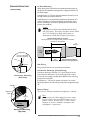
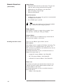
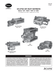
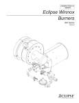
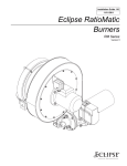
Installation Guide
No. 135, 7/99
L00061
Eclipse AirHeat Burners
AH Series version 2.00
(Patent Pending)
Eclipse Combustion
COPYRIGHT
DISCLAIMER NOTICE
LIABILITY AND
WARRANTY
2
Copyright 1999 by Eclipse Combustion, Inc. All rights
reserved worldwide. This publication is protected by federal
regulation and shall not be copied, distributed, transmitted,
transcribed or translated into any human or computer
language, in any form or by any means, to any third parties,
without the express written consent of Eclipse Combustion,
Inc., Rockford, Illinois, U.S.A.
We reserve the right to change the construction and/or
configuration of our products at any time without being obliged
to adjust earlier supplies accordingly.
The material in this manual is believed adequate for the
intended use of the product. If the product, or its individual
modules or procedures, are used for purposes other than
those specified herein, confirmation of their validity and
suitability must be obtained. Eclipse Combustion, Inc. warrants
that the material itself does not infringe any United States
patents. No further warranty is expressed or implied.
We have made every effort to make this manual as accurate
and complete as possible. Should you find errors or omissions,
please bring them to our attention so that we may correct
them. In this way we hope to improve our product
documentation for the benefit of our customers. Please send
your corrections and comments to our Documentation
Manager.
It must be understood that Eclipse Combustion’s liability for its
products, whether due to breach of warranty, negligence, strict
liability, or otherwise, is limited to the furnishing of such
replacement parts and Eclipse Combustion will not be liable for
any other injury, loss, damage or expenses, whether direct or
consequential, including but not limited to loss of use, income
of or damage to material arising in connection with the sale,
installation, use of, inability to use or the repair or replacement
of Eclipse Combustion’s products.
Any operation expressly prohibited in this Guide, any
adjustment, or assembly procedures not recommended or
authorized in these instructions shall void the warranty.
Eclipse AirHeat v2.00, Installation Guide No. 135, 7/99
About this manual
AUDIENCE
This manual has been written for people who are already
familiar with all aspects of a nozzle-mix burner and its add-on
components, also referred to as “the burner system.”
These aspects are:
• installation
• use
• maintenance.
The audience is expected to have had experience with this
kind of equipment.
PURPOSE
The purpose of this manual is to ensure the installation of a
safe, effective, and trouble-free combustion system is carried
out.
AIR HEAT
DOCUMENTS
Installation Guide No. 135
• This document
AirHeat Data Sheet 135
• Available for all AH models
• Required to complete design & selection
Design Guide No. 135
Used with Data Sheet to design burner system
AirHeat v2.00 Price List No. 135
Used to order burners
RELATED DOCUMENTS
• EFE 825 (Combustion Engineering Guide)
• Eclipse Bulletins and Info Guides: 710, 720, 732, 742, 760,
818, 832, 852, 854, 856, 610, 620, 630, 826, 820, 930,
I-354.
Eclipse AirHeat v2.00, Installation Guide No. 135, 7/99
3
DOCUMENT
CONVENTIONS
There are several special symbols in this document. You
must know their meaning and importance.
The explanation of these symbols follows below. Please read
it thoroughly.
d Danger:
Indicates hazards or unsafe practices which WILL
result in severe personal injury or even death.
Only qualified and well trained personnel are
allowed to carry out these instructions or
procedures.
Act with great care and follow the instructions.
HOW TO GET HELP
4
w
Warning:
Indicates hazards or unsafe practices which
could result in severe personal injury or
damage.
Act with great care and follow the instructions.
c
Caution:
Indicates hazards or unsafe practices which could result in
damage to the machine or minor personal injury, Act carefully.
n
Note:
Indicates an important part of the text. Read thoroughly.
If you need help, contact your local Eclipse Combustion
representative. You can also contact Eclipse Combustion at any
of the addresses listed on the back of this document.
Eclipse AirHeat v2.00, Installation Guide No. 135, 7/99
Table of contents
About this manual . . . . . . . . . . . . . . . . . . . . . . . . . .
Audience . . . . . . . . . . . . . . . . . . . . . . . . . . . . . . . . . . . .
Purpose . . . . . . . . . . . . . . . . . . . . . . . . . . . . . . . . . . . . .
AirHeat Documents . . . . . . . . . . . . . . . . . . . . . . . . . . .
Related Documents . . . . . . . . . . . . . . . . . . . . . . . . . . . .
Document Conventions . . . . . . . . . . . . . . . . . . . . . . . .
How to Get Help . . . . . . . . . . . . . . . . . . . . . . . . . . . . .
3
3
3
3
3
4
4
Table of Contents . . . . . . . . . . . . . . . . . . . . . . . . . . . 5
1
2
3
4
Introduction . . . . . . . . . . . . . . . . . . . . . . . . . . . . . . . . 7
Product Description . . . . . . . . . . . . . . . . . . . . . . . . . . . 7
Safety . . . . . . . . . . . . . . . . . . . . . . . . . . . . . . . . . . . . . .
Capabilities . . . . . . . . . . . . . . . . . . . . . . . . . . . . . . . . . . .
Operator Training . . . . . . . . . . . . . . . . . . . . . . . . . . . . .
Replacement Parts . . . . . . . . . . . . . . . . . . . . . . . . . . . .
8
9
9
9
Installation . . . . . . . . . . . . . . . . . . . . . . . . . . . . . . . . . .
Handling and Storage . . . . . . . . . . . . . . . . . . . . . . . . . . .
Approvals of Components . . . . . . . . . . . . . . . . . . . . . .
Electrical Wiring . . . . . . . . . . . . . . . . . . . . . . . . . . . . . . .
Gas Piping . . . . . . . . . . . . . . . . . . . . . . . . . . . . . . . . . . . .
Where to get standards . . . . . . . . . . . . . . . . . . . . . . . .
Pre-installation Checklist . . . . . . . . . . . . . . . . . . . . . . .
Burner Mounting . . . . . . . . . . . . . . . . . . . . . . . . . . . . . .
Installing the flame sensor . . . . . . . . . . . . . . . . . . . . . . .
Check List After Installation . . . . . . . . . . . . . . . . . . . . .
Prepare for adjustment . . . . . . . . . . . . . . . . . . . . . . . . .
10
10
10
11
11
11
12
12
14
15
15
Adjustment, Start & Stop . . . . . . . . . . . . . . . . . . . .
Introduction . . . . . . . . . . . . . . . . . . . . . . . . . . . . . . . . . .
Burner adjustment . . . . . . . . . . . . . . . . . . . . . . . . . . . .
Step 1 Reset the system . . . . . . . . . . . . . . . . . . . . .
Step 2 Set Air flow . . . . . . . . . . . . . . . . . . . . . . . . .
Step 3a Ignite the burner (Direct Spark) . . . . . . . .
Step 3b Ignite the burner (Pilot) . . . . . . . . . . . . . .
Step 4 Set high fire gas . . . . . . . . . . . . . . . . . . . . . .
Step 5 Set low fire gas . . . . . . . . . . . . . . . . . . . . . .
Step 6 Verify gas settings . . . . . . . . . . . . . . . . . . . . .
Step 7 Stop proceedure . . . . . . . . . . . . . . . . . . . . .
16
16
16
16
16
17
17
18
18
18
18
Eclipse AirHeat v2.00, Installation Guide No. 135, 7/99
5
5
Maintenance & Troubleshooting . . . . . . . . . . . . . .
Maintenance . . . . . . . . . . . . . . . . . . . . . . . . . . . . . . . . . .
Monthly Checklist . . . . . . . . . . . . . . . . . . . . . . . . . . . . .
Yearly Checklist . . . . . . . . . . . . . . . . . . . . . . . . . . . . . . .
Troubleshooting Procedures . . . . . . . . . . . . . . . . . . . .
19
19
19
20
21
Appendix . . . . . . . . . . . . . . . . . . . . . . . . . . . . . . . . . . . 24
Conversion Factors . . . . . . . . . . . . . . . . . . . . . . . . . . . . 24
Key to System Schematics . . . . . . . . . . . . . . . . . . . . . . 25
6
Eclipse AirHeat v2.00, Installation Guide No. 135, 7/99
Introduction
PRODUCT
DESCRIPTION
1
Eclipse AirHeat v2.00 Burners are line type burners ideal for
generating large volumes of clean, hot air. Applications include
ovens, dryers, fume incinerators, and similar industrial
equipment. Burners are constructed of aluminum burner
bodies and diverging stainless steel air wings. The burner
bodies supply fuel to the center of the air wings. The air and
fuel mixture inside the burner is controlled to optimize
emissions and efficiency.
AirHeat v2.00 Burners are assembled from straight sections
allowing for customized inputs. An integral combustion air
blower can be ordered mounted on the back of the burner’s
steel case. By supplying the correct air volume and pressure
to the burner, the blower allows stable operation over a wide
range of duct velocities without installing a profile plate
around the burner.
Brackets are available for slot firing or duct mounting and
flanges are available for continuous flange mounting. Right
hand or left hand gas piping can be supplied with BSP or NPT
connections. A reduced port fuel control valve can be
supplied with a variety of control motor and linkage options.
Ignition can be by direct spark or by spark ignited pilot.
Flame rod flame supervision can be from either or both ends.
Several air flow switches are also available factory mounted on
the burner.
AirHeat v2.00 Burners
Burner with blower
Burner less blower
with inlet gas
piping and fuel
control valve and
continuous mounting flanges.
Burner less blower
with inlet gas
piping and fuel control
valve and spark
ignited pilot.
Eclipse AirHeat v2.00, Installation Guide No. 135, 7/99
7
Safety
INTRODUCTION
SAFETY
2
This section is provided as a guide for the safe operation of
the AirHeat burner system. All involved personnel should
read this section carefully before operating this system.
d
Danger:
The AirHeat burners, described herein, are
designed to mix fuel with air and burn the
resulting mixture. All fuel burning devices are
capable of producing fires and explosions if
improperly applied, installed, adjusted,
controlled, or maintained.
Do not bypass any safety feature; fire or explosion
could result.
Never try to light a burner if it shows signs of
damage or malfunction.
8
w
Warning:
The burner might have HOT surfaces. Always wear protective
clothing when approaching the burner.
n
Note:
This manual provides information in the use of these burners
for their specific design purpose. Do not deviate from any
instructions or application limits described herein without
written advice from Eclipse Combustion.
Read the entire manual before attempting to start this
system. If you do not understand any part of the information
contained in this manual, contact your local Eclipse
representative or Eclipse Combustion before continuing.
Eclipse AirHeat v2.00, Installation Guide No. 135, 7/99
CAPABILITIES
Only qualified personnel, with good mechanical aptitude and
experience on combustion equipment, should adjust, maintain,
or troubleshoot any mechanical or electrical part of this
system.
OPERATOR TRAINING
The best safety precaution is an alert and trained operator.
Train new operators thoroughly and have them demonstrate
an adequate understanding of the equipment and its
operation. A regular retraining schedule should be
administered to ensure operators maintain a high degree of
proficiency.
REPLACEMENT PARTS
Order replacement parts from Eclipse Combustion only. All
Eclipse Combustion approved, customer supplied valves or
switches should carry UL, FM, CSA, CGA, and/or CE approval,
where applicable.
Eclipse AirHeat v2.00, Installation Guide No. 135, 7/99
9
Installation
3
INTRODUCTION
In this section you will find important notices about safe
operation of the burner:
HANDLING
STORAGE
Handling:
1. Make sure that the components are clean and free of
damage.
AND
2. Protect the components from weather, damage, dirt and
moisture.
• Transport in original shipping container
• Do not drop
3. Protect the components from excessive temperatures and
humidity.
4. Use appropriate support equipment, i.e. harnesses, straps,
chains etc. when lifting burner components.
Storage:
1. Make sure that the area is clean.
2. Store the components in a cool, clean, dry room.
3. After you have made sure everything is present and in
good condition, keep the components in the original
package as long as possible.
APPROVALS OF
COMPONENTS
Limit Controls and Safety
Equipment
All limit controls and safety equipment must comply with the
current following standards:
• NFPA Standard 86
• NFPA Standard 86C
• UL
• FM
• CGA
• EN 746-2
• all applicable local codes and/or standards.
10
Eclipse AirHeat v2.00, Installation Guide No. 135, 7/99
Electrical wiring
All electrical wiring must comply with one of these standards:
•
•
•
•
Gas Piping
ANSI-C11981
EN 746-2
the electrical wiring must be acceptable to the local
authority having jurisdiction
All gas piping must comply with one of these standards:
•
•
•
•
Where to get standards
NFPA Standard 70
NFPA Standard 70
ANSI Z223
EN 746-2
the gas piping must be acceptable to the local authority
having jurisdiction
The NFPA Standards are available from:
National Fire Protection Agency
Batterymarch Park
Quincy, MA 02269
The ANSI Standards are available from:
American National Standard Institute
1430 Broadway
New York, NY 10018
The UL Standards are available from:
333 Pfingsten Road
Northbrook, IL 60062
The FM Standards are available from:
1151 Boston-Providence Turnpike
P.O. Box 9102
Norwood, MA 02062
Information on the EN standards, and where to get the
standards is available from:
Comité Européen de Normalisation
Strassartstraat 36
B-1050 Brussels
Phone: +32-25196811
Fax: +32-25196819
Comité Européen de Normalisation Electronique
Strassartstraat 36
B-1050 Brussels
Phone: +32-25196871
Fax: +32-25196919
Eclipse AirHeat v2.00, Installation Guide No. 135, 7/99
11
PRE-INSTALLATION
CHECKLIST
Air Supply
If there are corrosive fumes or materials in the surrounding
air, find an uncontaminated source to supply air to the
burner. Observe ambient temperature limits as stated in
Data 135.
• Combustion Air From Outside Duct
Provide an opening in the burner room of at least one square
inch per 4000 BTU/hr (6 cm2 per 1 kW) to supply the
burner intake with fresh, outdoor, combustion air.
• Combustion Air From Inside Duct
There must be a minimum of 18% O2 present in the process
air flow to ensure proper burner performance.
Exhaust
Do not allow exhaust gases to accumulate in the work area.
Provide a means for exhausting these gases from the building.
Access
Install the burner so it may be easily accessed for inspection
and maintenance.
Environment
Be sure the burner operating environment matches the
original operating specifications. Check the following items:
• voltage, frequency, and stability of electrical power
• fuel type and fuel supply pressure
• adequate fresh, clean, combustion air
• humidity, altitude, and temperature of the supply air
• presence of damaging corrosive gases in the air
• prevent direct exposure to water.
BURNER MOUNTING
Note:
Mounting dimensions for all mounting options are found in
Data 135.
n
Guidlines for all mounting options
• Center the burner in the duct
• Allow a minimum of 41” (1042 mm) from burner to nearest
point of possible flame impingement at an input of
1,000,000 Btu/hr. (961kW/m) and ∆P air = 1.0”w.c.
See Data 135 for more information about flame lenghts at
other burner settings.
• On burners longer than 36” (914 mm), use a hanger or a
pedestal to support the blower and motor.
• The duct structure must be strong enough to support the
weight of the burner. If necessary, reinforce the mounting
area.
• Process air velocity must be within the limits stated on
page 5 of Data 135.
12
Eclipse AirHeat v2.00, Installation Guide No. 135, 7/99
BURNER MOUNTING
(CONTINUED)
In Duct Mounting
When laying out the duct, allow enough length downstream of
the burner to avoid flame impingement; see page 2 of Data 135
for flame lenghts.
Provide at least 3” (76 mm) clearance between the burner and
the top, bottom and sides of the duct.
Profile plates are not required for good burner operation, but
uniform velocity must be maintained for the full length of the
burner. If velocity is not uniform, profile plates can be used to
correct this condition.
Caution
Profile plates should be positioned flush with the firing
end of the burner. If necessary, the plates can be located
up to 1/2” back from the firing end, but under no
circumstances should they be in front of the burner.
c
Minimum Distance Before Transition
Rectangular Ducts: One Height or Width, Whichever is Greater
Round Ducts: One Diameter
7.5
Maximum
Air Flow
AH
Burner
Customer Supplied
Mounting Hardware
41"
(1042 mm)
Duct
Gasket
Continuous Mounting
(Side View)
Insulation
Minimum Distance Before
Possible Flame Impingement
Slot Firing
Firing end of the burner must extend into the duct.
Continuous Mounting (Sealed Firing)
Provide an opening in the duct 1/2” (12mm) larger than the
external burner dimensions. (1/4” (6mm) gap on all 4 sides.)
Customer must supply a suitable gasket between the mounting
flange and the duct wall.
If insulation is 1” (25mm) or greater in thickness, it must be
beveled away from the left and right end plates at approximately
45°.
Burner Piping
The burner is factory assembled and shipped as ordered.
Appliance
Wall
45˚
Approx.
Burner
n
Note:
If it is necessary to redirect piping, the burner may be
inverted. Burner, fuel control BV and blower are not
position concious. All other items i.e. valves, switches
actuators etc. must be installed in accordance with
manufacturers requirements.
Continuous Mounting
(Top View)
Eclipse AirHeat v2.00, Installation Guide No. 135, 7/99
13
BURNER MOUNTING
(CONTINUED)
Supply Piping
• Locate the valve train close to the burner. The gas must
reach the burner during the fixed trial for ignition.
• Sufficiently size shut off valves in the valve train.
• Make sure piping is large enough.
• Minimize piping elbows.
Pipe Connections
• Installation of a pipe union in the gas line is recommended
to simplify burner removal.
• Use of flexible pipe is optional.
Note:
Flexible pipe causes higher pressure drops than standard
pipe. Consider this when sizing your gas lines.
Piping Support
Use brackets or hangers to support the gas piping. If you
have questions, consult your local gas company.
Control Motor
Install a control motor to modulate the gas control valve if
not previously installed on the burner.
Installing the flame sensor
There are two different types of flame sensors:
U.V. scanner:
Each AirHeat burner is capable of U.V. flame monitoring. The
burner will not come equipped with a U.V. scanner. A ½”
NPT connection is provided on each AirHeat burner for the
connection of a U.V. scanner.
For detailed information on how to install and connect an
Eclipse U.V. scanner, refer to:
– straight U.V. scanner; Bulletin / Info Guide 854
– 90° U.V. scanner; Bulletin / Info Guide 852
– self-check U.V. scanner; Bulletin / Info Guide 856.
Flame rod:
If the flame rod option was selected when the burner was
ordered, the burner will be delivered with the flame rod
already installed on the burner
For detailed information on how to install and connect a
flame rod, refer to:
– Bulletin / Info Guide 832.
14
Eclipse AirHeat v2.00, Installation Guide No. 135, 7/99
CHECK LIST AFTER
INSTALLATION
To verify the system was properly installed, perform the
following checks:
1. Be sure there are no leaks in the gas lines.
2. Be sure all the components contained in the flame
monitoring and control system are properly installed.
This includes verifying that:
• all the switches are installed in the correct locations.
• all wiring and pressure lines are properly connected.
3. Be sure all components of the spark ignition system are
installed and functioning properly.
4. Be sure the blower rotates in the proper direction. If the
rotation is incorrect, have a qualified electrician rewire the
blower to rotate in the proper direction.
5. Be sure all valves are installed in the proper location and
correctly oriented relative to the flow direction.
PREPARE FOR
ADJUSTMENT
After installation of the burner system components is
complete, the following steps should be followed in order to
prepare for adjustment:
1. Set the air flow switch so that it drops out at 20% below
the maximum pressure of the combustion air blower.
2. Set the low gas pressure switch at 20% below the gas
pressure measured at the inlet to the main gas valve train.
3. Set the high gas pressure switch at 20% above the gas
pressure measured at the inlet to the main gas valve train.
4. Close all manual valves feeding the burner.
5. Try to ignite the burner before the purge and other timers
have finished their cycles. Make sure that the flame
monitoring system indicates a flame failure.
6. Trip out the pressure switches and other limit interlocks.
Make sure that the main gas valve train closes.
d
Danger:
If simulated limits or simulated flame failures do
not shut down the fuel system within the
required failure response time, immediately
correct the problem before proceeding.
Eclipse AirHeat v2.00, Installation Guide No. 135, 7/99
15
Adjustment, Start &
Stop
INTRODUCTION
4
In this chapter you will find instructions on how to start and
stop a burner. The chapter begins with general instructions
that are useful for adjustment.
Danger:
d
The AirHeat burners, described herein, are
designed to mix fuel with air and burn the
resulting mixture. All fuel burning devices are
capable of producing fires and explosions if
improperly applied, installed, adjusted,
controlled, or maintained.
Do not bypass any safety feature; fire or
explosion could result.
Never try to light a burner if it shows signs of
damage or malfunction.
BURNER ADJUSTMENT
If you are adjusting an AirHeat burner for the first time, you
must follow these steps:
1. Reset the system
2. Set air flow
3. Ignite the burner
4. Set high fire gas
5. Set low fire gas
6. Verify gas settings
7. Stop Procedure
Step 1: Reset the system
1. Start circulating duct fan.
2. Close these valves
- the automatic gas valves
- the manual gas cocks
3. Start the combustion air blower
Step 2: Set air flow
Measure the air pressure drop across the burner between Tap
“A” and Tap “C”. (See page 5 of Data 135.) Turn the disc on
the blower air inlet until the air pressure is between 0.6”w.c.
(1.5mbar) minimum and 1.2”w.c. (3.0mbar) maximum. For a
given input, lower air pressure drops will produce a longer
flame, and higher drops will produce a shorter flame with
slightly higher CO levels.
16
Eclipse AirHeat v2.00, Installation Guide No. 135, 7/99
There are two separate ignition procedures which depend
upon whether or not a pilot is installed on the burner. Each
procedure is unique and both are outlined below.
Warning:
Both procedures assume that a flame monitoring
control system is installed and is serviceable.
1. Drive the gas control valve to low fire.
w
Step 3a: Ignite the burner
(Option 1: Direct Spark
Ignition))
n
Note:
All AirHeat burners are limited to direct spark ignition at
inputs below 60% of maximum.
2. Make sure the combustion air blower is running.
3. Open all manual gas valves feeding the burner.
4. Initiate the ignition sequence through the flame
monitoring control system.
5. Verify that the burner has ignited.
If the burner does not ignite:
a) Try to ignite again to purge the air out of the gas piping.
b) If the burner does not ignite after one or two
additional ignition attempts, see the Trouble shooting
Guide contained in the Maintenance & Troubleshooting
section of this guide.
Main Gas
shut-off
valve train
Step 3b: Ignite the burner
(Option 2: Burner equipped
with spark ignited pilot)
Handle
(Shown in
Open Position)
Top Screw
Adjusting Screw
(Clockwise for less pilot gas,
Counterclockwise for more pilot gas)
n
Note:
Ignition is possible at all inputs using spark ignited pilot.
1. Drive the gas control valve to low fire.
2. Make sure the combustion air blower is running.
3. Open all pilot gas valves including the handle of the
adjustable port pilot gas cock.
4. Verify that the pilot has ignited.
5. Initiate the ignition sequence through the flame
monitoring control system.
If the pilot does not ignite:
a) Try to ignite again to purge the air out of the gas piping.
b) If the pilot does not ignite after one or two additional
ignition attempts, see the Trouble shooting Guide
contained in the Maintenance & Troubleshooting
section of this guide.
Main Gas
shut-off
valve train
Adjustable Port Pilot Gas Cock
Pilot
NC
Eclipse AirHeat v2.00, Installation Guide No. 135, 7/99
17
Step 4: Set high fire gas
1. If the burner is ignited, set the main gas pressure regulator
for 10” w.c. outlet pressure.
2. Drive the main gas control valve to high fire (full open).
3. Verify air flow with the burner firing, if necessary, repeat
Step 2 “Set air flow”.
4. Make sure that pressure taps B and C are open.
5. Connect the manometer to taps B and C.
6. Measure the gas differential pressure.
7. Use the fuel ∆ P curve from Data Sheet 135 for the gas
being used to find the differential gas pressure needed at
high fire.
8. Adjust the outlet pressure from the main gas pressure
regulator to achieve the desired gas flow.
9. Once the chamber conditions stabilize, (i.e. pressure and
temperature), repeat Steps 3 through 8.
10. Remove the manometer.
11. Close the pressure taps.
Step 5: Set low fire gas
1. Drive the main gas control valve to low fire.
2. Adjust the control valve linkage to provide the desired low
fire gas flow.
n
Note:
It is very difficult to measure the very low gas pressures
experienced at low fire, and it may be necessary to rely on
visual inspection of the flame. This is especially true when
gas turndowns in excess of 20 to 1 are being used. The
main intent is to provide a stable flame with good flame
signal that will not cause the chamber temperature to
overshoot.
Step 6: Verify gas settings
Make sure that all settings are still the same after cycling the
system several times between high and low fire.
Step 7: Stop Procedure
c
18
Eclipse AirHeat v2.00, Installation Guide No. 135, 7/99
Caution:
Do not turn the combustion air blower off until the
chamber temperature is below 250ºF (121ºC). This will
prevent hot gases from back flowing into the burner and
blower causing damage to the burner.
1. Stop the burner through the burner control system.
2. Run the combustion air blower until the chamber
temperature drops below 250ºF (121ºC).
3. Shut off the combustion air blower.
4. Close all manual gas valves to the burner.
Maintenance &
Troubleshooting
INTRODUCTION
5
This chapter is divided into two sections:
• Maintenance procedures
• Troubleshooting guide
Preventive maintenance is the key to a reliable, safe and
efficient system. The core of any preventive maintenance
system is a list of periodic tasks.
MAINTENANCE
Note:
These are guidelines only. The customer should make the
final determination on maintenance intervals and tasks to
be performed while considering the working environment.
Monthly Checklist
1. Inspect the flame sensing devices for good condition and
cleanliness.
2. Check for proper air and gas pressures (Refer to the
Data Sheet 135).
3. Test all the system alarms for proper response signals.
4. Check and clean igniter electrodes.
5. Check valve motors and control valves for free, smooth
action and adjustment.
6. Check for the proper operation of ventilating equipment.
7. Test the interlock sequence on all safety equipment.
Manually force each interlock to intentionally fail while at
the same time noting if related equipment closes or stops
as specified by the manufacturer. Test the flame safeguard
by manually shutting off the gas to the burner.
8. Test the manual gas shut off cocks for proper operation.
9. Clean and/or replace the combustion air blower filter if
applicable.
10. Inspect and clean the combustion air blower rotor.
Eclipse AirHeat v2.00, Installation Guide No. 135, 7/99
19
Yearly Checklist
20
1. Leak test the safety shut-off valves for tightness of
closure.
2. Test the pressure switch settings by checking the switch
movements against pressure settings and comparing these
with the actual impulse pressure.
3. Visually check igniter cable and connectors.
4. Be sure the following components are not damaged or
distorted:
• the burner bodies and air wings.
• the igniter.
• the flame sensors.
Eclipse AirHeat v2.00, Installation Guide No. 135, 7/99
TROUBLESHOOTING PROCEDURES
PROBLEM
Cannot initiate a start
sequence.
POSSIBLE CAUSE
•
Air pressure switch has not
made contact.
Check air pressure switch
adjustment.
Check air filter.
Check blower rotation.
Check outlet pressure from
blower.
•
High gas pressure switch has
activated.
Low gas pressure switch has
activated.
Check incomming gas pressure;
adjust if necessary.
Check pressure switch setting
and operation.
•
Purge cycle not completed.
Check flame safeguard system
or purge timer.
•
Malfunction of the flame
safeguard system (e.g., shortedout flame sensor or electrical
noise in the sensor line).
No power to the control unit.
Have a qualified electrician
troubleshoot and correct the
problem.
Main power is off.
Be sure the main power to the
system is switched to the “on”
position.
•
•
•
Start-up sequence runs but
burner does not light.
SOLUTION
PILOT IGNITION ONLY
•
Gas pressure into pilot
regulator too low.
•
Pilot gas cock closed.
Check outgoing gas pressure of
main regulator; increase if
necessary.
Open pilot gas cock.
•
Pilot solenoid valve does not
open.
Gas adjusting valve set too low.
Have qualified electrician check
power supply to solenoid.
Increase gas flow. See page 17.
Air in the pilot gas line.
Repeat start-up several times to
purge air from gas line.
•
•
PILOT IGNITION OR DIRECT SPARK
No ignition:
• Attempting to ignite at inputs
greater than 60% (direct spark).
• Weak or non-existent spark.
•
There is no power to the
ignition transformer.
•
Open circuit between the
ignition transformer and the
igniter.
Reduce start point gas flow.
Verify control circuit.
Verify ignition transformer is a
6,000 - 8,000 volt transformer.
(Not half-wave)
Restore the power to the
ignition transformer.
Repair or replace the wiring to
the igniter.
Eclipse AirHeat v2.00, Installation Guide No. 135, 7/99
21
PROBLEM
Start-up sequence runs but
burner does not light.
(continued)
POSSIBLE CAUSE
No ignition (continued):
• The igniter needs cleaning.
The igniter is not correctly
grounded to the burner.
Clean the threads on the igniter
and the burner. NOTE: Do not
apply grease to the threads on
the igniter.
•
Igniter insulator is broken.
Igniter is grounding out.
Inspect the igniter. Replace if
broken.
•
Gas valve does not open.
No flame signal:
• Broken flamerod
• Dirty UV scanner lens
• Flamerod grounding out
The burner does not go to
high fire.
Burner does not achieve
capacity.
22
Clean the igniter.
•
Not enough gas:
• The gas flow into the burner is
too low.
The low fire flame is weak or
unstable.
SOLUTION
Check the start-up settings.
Adjust low fire gas setting if
necessary.
Check the wiring to the
automatic gas shut-off valve.
Check the output from the
flame safeguard.
Open manual gas cock.
Replace if necessary.
Inspect and clean sensor.
Verify that the flamerod is
installed correctly and is the
correct length.
•
Not enough gas
•
Incorrect air flow setting
•
Not enough gas pressure out of
main gas regulator.
Adjust pressure regulator so
pressure is provided as stated
in Data 135.
•
Gas pressure drops as input is
increased.
Check for clogging of valves and
regulators in gas line. Pressure
regulator may be incorrectly
sized. Replace if necessary.
•
Main gas control valve is not
functioning.
Check actuator and linkage.
•
Main gas control valve is not
functioning.
Check actuator and linkage.
•
Burner is firing below rated
input.
•
Burner gas holes are plugged.
Check gas pressure differential.
Adjust main gas pressure
regulator as necessary.
Inspect gas holes for dirt or lint
as needed.
Check start-up settings and
adjust to increase gas flow.
Check air pressure drop across
the burner and adjust.
Eclipse AirHeat v2.00, Installation Guide No. 135, 7/99
PROBLEM
Main flame is uneven along the
length of the burner.
Main flame is yellow and long
at high fire.
CO emission is too high.
POSSIBLE CAUSE
SOLUTION
•
Air pressure drop/velocity is
too low.
Increase air pressure drop.
•
Poor air distribution in duct.
Check profiling and duct
obstructions.
•
Air wings are dirty, holes are
clogged.
Inspect and clean air wings if
necessary.
•
Gas pressure too high at
burner inlet.
Check gas pressure against
design. Adjust main gas
pressure regulator.
•
Air wings are dirty, holes are
clogged.
Inspect and clean air wings if
necessary.
•
Air pressure drop/velocity too
low.
Open air damper on
combustion air blower.
•
Burner is outside range
specified in Data 135.
Adjust burner settings.
•
Process air velocity exceeds
limits given in Data 135.
Bring velocity within limits;
adjust process air blower.
Eclipse AirHeat v2.00, Installation Guide No. 135, 7/99
23
Appendix
CONVERSION
FACTORS
Metric to English.
From
To
Multiply By
cubic meter (m3)
cubic foot (ft3)
35.31
cubic meter/hour (m3/h)
cubic foot/hour (cfh)
35.31
degrees Celsius (ºC)
degrees Fahrenheit (ºF)
(ºC x 1.8) + 32
kilogram (kg)
pound (lb)
2.205
kilowatt (kW)
BTU/hr
3414
meter (m)
foot (ft)
3.28
millibar (mbar)
inches water column (“w.c.)
0.401
millibar (mbar)
pounds/sq in (psi)
14.5 x 10⁻³
millimeter (mm)
inch (in)
3.94 x 10⁻²
MJ/m3 (normal)
BTU/ft3 (standard)
2.491 x 10⁻²
kiloPascals (kPa)
millibar (mbar)
10
meter (m)
millimeter (mm)
1000
millibar (mbar)
kiloPascals (kPa)
0.1
millimeter (mm)
meter (m)
0.001
From
To
Multiply By
BTU/hr
kilowatt (kW)
0.293 x 10⁻³
cubic foot (ft3)
cubic meter (m3)
2.832 x 10⁻²
degrees Fahrenheit (ºF)
degrees Celsius (ºC)
(ºF – 32) ÷ 1.8
foot (ft)
meter (m)
0.3048
inches (in)
millimeter (mm)
25.4
inches water column (“wc)
millibar (mbar)
2.49
pound (lb)
kilogram (kg)
0.454
pounds/sq in (psi)
millibar (mbar)
68.95
Metric to Metric.
English to Metric.
3
BTU/ft (standard)
24
3
MJ/m (normal)
Eclipse AirHeat v2.00, Installation Guide No. 135, 7/99
40.14
KEY TO SYSTEM
SCHEMATICS
Symbol
Appearance
These are the symbols used in the schematics.
Name
Remarks
Bulletin/
Info Guide
AirHeat
NC
Main Gas Shutoff
Valve Train
Eclipse Combustion, Inc.
strongly endorses NFPA as a
minimum
Gas Cock
Gas cocks are used to
manually shut off the gas
supply on both sides of the
main gas shut-off valve train.
710
Solenoid valves are used to
automatically shut off the gas
supply on a bypass gas system
or on small capacity burners.
760
Solenoid Valve
(normally closed)
Automatic Gas
Control Valve
Pressure Regulator
An automatic gas control
valve adjusts gas flow to the
burner based on control
system requirements.
A pressure regulator reduces
gas pressure to a stable,
usable pressure.
Eclipse AirHeat v2.00, Installation Guide No. 135, 7/99
756
720
684
25
Eclipse Combustion