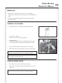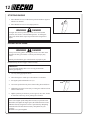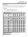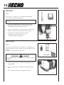
1
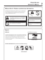
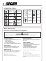
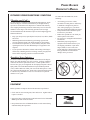
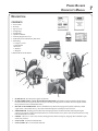
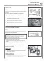
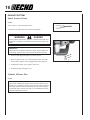
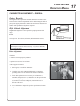
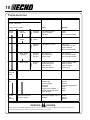
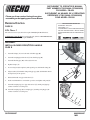
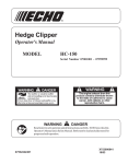
Power Blower
Operator's Manual
MODELS:
PB-650
Serial Number 04001001 - 04002000
WARNING
DANGER
Read rules for safe operation and all instructions carefully. ECHO provides this
Operator's Manual which must be read and understood for proper and safe operation.
X7501126900
X750003020
06/01
POWER BLOWER
OPERATOR'S MANUAL
MANUAL SAFETY SYMBOLS AND IMPORTANT INFORMATION
Throughout this manual and on the product itself, you will find safety
alerts and helpful, information messages preceded by symbols or key
words. The following is an explanation of those symbols and key
words and what they mean to you.
This symbol accompanied by the words WARNING
and DANGER calls attention to an act or condition
that can lead to serious personal injury to operator
and bystanders.
The circle with the slash symbol means whatever is
shown within the circle is prohibited.
IM
PO
RT
AN
T
IMPORTANT The enclosed message
provides information necessary for the
protection of the unit.
NOTE This enclosed message provides tips for use, care and maintenance
of the unit.
SAFETY
DECALS
HOT DECAL (near muffler)
Locate these safety decals on your unit. The complete unit illustration,
found in the "DESCRIPTION" section, will help you locate them. Make
sure the decals are legible and that you understand and follow the
instructions on them. If a decal cannot be read, a new one can be
ordered from your ECHO dealer. See PARTS ORDERING instructions
for specific information.
P/N 89016006361
GENERAL WARNING DECAL (located on top of blower housing)
P/N 89016009461
TE
NO
3
4
INTERNATIONAL SYMBOLS
Symbol form/shape
Symbol
description/application
Symbol form/shape
Symbol
description/application
Read and understand
Operator's Manual.
Fuel and oil mixture
Wear eyes, ears and
head protection
Finger Severing
Symbol form/shape
Symbol
description/application
Symbol form/shape
Wear hand
protection. Use
two handed.
Carburetor adjustment
- Low speed mixture
Wear slip
resistant foot
wear.
Safety/Alert
DO NOT allow
flames or sparks
near fuel.
Ignition
ON/OFF
Engine choke
control.
Emergency stop
Hot
Surface
Symbol
description/application
Primer bulb
Carburetor adjustment
- High speed mixture
Carburetor adjustment
- Idle speed
DO NOT smoke
near fuel.
SAFETY INSTRUCTIONS
PERSONAL CONDITION AND SAFETY EQUIPMENT
WARNING
DANGER
Power Blower users risk injury to themselves and others if the power blower is used improperly and or safety
precautions are not followed. Proper clothing and safety gear must be worn when operating a blower.
Physical Condition --
Hearing Protection --
Your judgment and physical dexterity may not be good:
• if you are tired or sick,
• if you are taking medication,
• if you have taken alcohol or drugs.
Operate unit only if you are physically and mentally well.
ECHO recommends wearing hearing protection whenever
unit is used.
Eye Protection -Wear eye protection that meets ANSI Z87.1 or CE
requirements whenever you operate the blower.
Hand Protection -Wear no-slip, heavy duty work gloves to improve your
grip on the blower handle. Gloves also reduce the
transmission of machine vibration to your hands.
Breathing Protection -Wear a face mask to protect against dust.
Proper Clothing -Wear snug fitting, durable clothing;
• Pants should have long legs, shirts with long sleeves.
• DO NOT WEAR SHORTS,
• DO NOT WEAR TIES, SCARVES, JEWELRY.
Wear sturdy work shoes with nonskid soles;
• DO NOT WEAR OPEN TOED SHOES,
• DO NOT OPERATE UNIT BAREFOOTED.
Keep long hair away from engine and blower intake. Retain
hair with cap or net.
Hot Humid Weather -Heavy protective clothing can increase operator fatigue
which may lead to heat stroke. Schedule heavy work for
early morning or late afternoon hours when temperatures
are cooler.
POWER BLOWER
OPERATOR'S MANUAL
EXTENDED OPERATION/EXTREME CONDITIONS
To reduce the risk of RSI/CTS, do the
following:
Vibration and Cold -It is believed that a condition called Raynaud’s Phenomenon, which
affects the fingers of certain individuals may be brought about by
exposure to vibration and cold. Exposure to vibration and cold may
cause tingling and burning sensations followed by loss of color and
numbness in the fingers. The following precautions are strongly
recommended because the minimum exposure which might trigger the
ailment is unknown.
• Keep your body warm, especially the head, neck, feet, ankles, hands
and wrists.
• Maintain good blood circulation by performing vigorous arm
exercises during frequent work breaks and also by not smoking.
• Limit the hours of operation. Try to fill each day with jobs where
operating the blower or other hand-held power equipment is not
required.
• If you experience discomfort, redness and swelling of the fingers
followed by whitening and loss of feeling, consult your physician
before further exposing yourself to cold and vibration.
Repetitive Stress Injuries -It is believed that overusing the muscles and tendons of the fingers,
hands, arms and shoulders may cause soreness, swelling, numbness,
weakness and extreme pain in those areas. Certain repetitive hand
activities may put you at a high risk for developing a Repetitive Stress
Injury (RSI). An extreme RSI condition is Carpal Tunnel Syndrome
(CTS), which could occur when your wrist swells and squeezes a vital
nerve that runs through the area. Some believe that prolonged exposure
to vibration may contribute to CTS. CTS can cause severe pain for
months or even years.
EQUIPMENT
Before operation a complete check of the unit must be performed:
• Check unit for loose/missing nuts, bolts and screws. Tighten and/or
replace as needed.
• Inspect fuel lines, tank and area around carburetor for fuel leaks. DO
NOT operate unit if leaks are found.
• Keep exhaust area clear of flammable debris. Avoid contact during
and immediately after operation.
• Avoid using your wrist in a bent,
extended or twisted position. Instead try
to maintain a straight wrist position.
Also, when grasping, use your whole
hand, not just the thumb and index finger.
• Take periodic breaks to minimize repetition and rest your hands.
• Reduce the speed & force in which you
do the repetitive movement.
• Do exercises to strengthen the hand and
arm muscles.
• Immediately stop using all power
equipment and consult a doctor if you
feel tingling, numbness or pain in the
fingers, hands, wrists or arms. The
sooner RSI/CTS is diagnosed, the more
likely permanent nerve and muscle
damage can be prevented.
5
6
SAFE OPERATION
Determine Operation Area -• Review area to be cleared. Look for potential hazards
such as stones or metal objects.
• Spectators and fellow workers must be warned, and
children and animals prevented from coming nearer than
15 m (50 ft.) while the blower is in use.
• Take wind conditions into account: avoid open doors
and windows.
• Provide all operators of this equipment with the
Operator's Manual and instructions for safe operation.
• Do not point blower at people or animals.
• Start unit on ground with throttle at idle. Check that
blower pipe is not blocked by the ground or by any
objects.
WARNING
DANGER
Do not operate this product indoors or in inadequately ventilated areas. Engine exhaust contains
poisonous emissions and can cause serious injury or
death.
Keep A Solid Stance
• Maintain footing and balance at all times. Do not stand
on slippery, uneven or unstable surfaces. Do not work
in odd positions or on ladders.
• Do not perform Maintenance or Assembly procedures
with engine running.
Noise Control
• Follow local noise regulations on sound levels and
hours of operations. Use only during appropriate hours.
• Never use a higher speed setting then necessary to
perform a task. The higher the engine speed the louder
the blower noise.
• Be a good neighbor.
Avoid Hot Surfaces
• During operation, the muffler or catalytic muffler and
surrounding cover may become extremely hot. Avoid
contact during and immediately after operation. Always
keep exhaust area clear of flammable debris. Allow the
engine and muffler to completely cool before performing
any maintenance activity.
Keep A Firm Grip
• Hold handle with fingers together encircling the handle.
EMISSION CONTROL
IMPORTANT ENGINE INFORMATION
EPA Phase II
The emission control system for this engine is EM (Engine
Modification).
An Emission Control Label is located on the unit. (This is
an EXAMPLE ONLY, information on label varies by
engine FAMILY).
ENGINE FAMILY:
1EHXS.0635RA
DISPLACEMENT: 63.3 CC
THIS ENGINE MEETS U.S. EPA PAHSE II EMISSION
REGULATIONS FOR S.O.R.E. REFER TO OWNER'S
MANUAL FOR MAINTENANCE SPECIFICATIONS AND
ADJUSTMENTS. EMISSION COMPLIANCE PERIOD : 300
HRS.
PRODUCT EMISSION DURABILITY
The 300 hour emission durability period is the time span selected by the manufacturer certifying the engine emissions
output meets applicable California emissions regulations, provided that approved maintenance procedures are
followed as listed in the Maintenance Section of this manual.
IMPORTANT This spark ignition system complies with Canadian ICES-002.
POWER BLOWER
OPERATOR'S MANUAL
7
DESCRIPTION
CONTENTS
1 - Power Head
1 - Flex Pipe
1 - Pipe w/swivel
1 - Straight Pipe
1 - Straight Pipe
1 - Operator's Manual
1 - Warranty Registration Card
1 - ECHO Emissions and Warranty Statement
1 - Plastic Bag
2 - Clamps w/screws
1 - Stick Handle
1 - Bolt 6x45
1 - Washer 6
1 - Wing nut
1-Bottle ECHO 2-Stroke Oil Mix
11
12
10
1
13
9
2
8
7
6
3
5
1.
2.
3.
4.
5.
6.
7.
4
SPARK PLUG - Provides spark to ignite fuel mixture.
SPARK ARRESTOR - CATALYTIC MUFFLER / MUFFLER - The muffler or catalytic muffler controls exhaust
noise and emission. The spark arrestor screen prevents hot, glowing particles of carbon from leaving the muffler.
Keep exhaust area clear of flammable debris.
RECOIL STARTER HANDLE - Pull recoil handle slowly until starter engages, then quickly and firmly. When
engine starts, return handle slowly. DO NOT let handle snap back or damage to unit will occur.
PRIMER BULB - Pumping primer bulb before starting engine draws fresh fuel from the fuel tank priming the
carburetor for starting. Pump primer bulb until fuel is visible and flows freely in the clear fuel tank return line. Pump
bulb an additional 4 or 5 times.
CHOKE - Move lever UP to close choke (starting position) and for emergency stopping. Move DOWN to open
choke (run position).
FUEL TANK - Contains fuel and fuel filter.
FUEL TANK CAP - Covers and seals fuel tank.
8
8.
9.
10.
11.
12.
13.
AIR CLEANER - Contains replaceable air filter element.
BLOWER PIPES - Twist lock design.
THROTTLE POSITION LEVER/STOP SWITCH - Combination stop switch and variable speed throttle lever.
When the lever is moved all the way forward the blower is at Wide Open Throttle (W.O.T.). When the lever is
moved rearward to detent, the blower is at idle. When the lever is moved rearward past the idle detent the blower will
stop.
SAFETY DECAL - Lists important safety precautions.
HANDLE - Rotates downward for throttle control access. Spring loaded for flexible operation.
SHOULDER HARNESS - Used to support unit on operator's back. The straps are adjustable.
ASSEMBLY
SPECIFICATIONS
MOD E L
P B -650
Length
375 mm (14.76 i n.)
Wi dth
485 mm (19.1 i n.)
Hei ght
527 mm (20.75 i n.)
Wei ght (dry)
10.4 kg (23.0 lb.)
E ngi ne Type
A i r cooled, two-stroke, si ngle cyli nder gasoli ne engi ne
D i splacement
63.3 cc (3.86 cu. i n.)
B ore
48.0 mm (1.89 i n.)
S troke
35.0 mm (1.38 i n.)
C arburetor
Igni ti on S ystem
S park P lug
E xhaust S ystem
Fuel
Fuel/Oi l Rati o
Gasoli ne
Oi l
Fuel Tank C apaci ty
Recoi l S tarter S ystem
Walbro D i aphragm, model WYK w/pri mer bulb
Flywheel Magneto, capaci tor di scharge i gni ti on type
NGK B P MR-8Y Gap 0.65 mm (0.026 i n.)
S park A rrestor Muffler
Mi xed (Gasoli ne and Two-stroke Oi l)
50:1 E C HO Hi gh P erformance, two-stroke ai r cooled engi ne oi l
89 Octane unleaded. D O NOT use fuel contai ni ng methyl alcohol, more
than 10% ethyl alcohol or 15% MTB E .
50:1 E C HO Hi gh P erformance, two-stroke ai r cooled engi ne oi l
2.07 li t. (70.0 US fl. oz.)
A utomati c Recoi l S tarter C entri fugal Type
Idle S peed
2350 - 2850 (RP M)
Wi de Open Throttle S peed
6800 - 7300 (RP M)
Maxi mum A i r S peed
(Measured at pi pe end)
338 K M/H (210 mph)
A verage A i r Volume
(Measured at pi pe end)
18.1 cu. m/mi n. (640 cu. ft./mi n.)
Maxi mum A i r Volume
(Measured at housi ng)
34.0 cu. m/mi n. (1200 cu. ft./mi n.)
POWER BLOWER
OPERATOR'S MANUAL
WARNING
9
DANGER
Never perform maintenance or assembly procedures with engine
running or serious personal injury may result.
INSTALL BLOWER PIPES
/ STICK HANDLE
1.
Assemble straight pipe with swivel (A) into flexible pipe (B).
2.
Assemble flexible pipe (B) to elbow (D) on blower.
3.
Assemble clamps (C) onto both ends of flexible pipe (B) and
tighten.
D
A
C
B
C
F
G
4.
Loosen wing nut (E) completely and expand open, stick handle
clamp (F).
H
E
A
5.
Align notches (G) in handle clamp with pipe pegs (H). Stick handle
should be angled away from operator.
6.
Slide stick handle onto pipe with swivel (A).
7.
Position stick handle for comfortable operation and tighten wing
nut (E).
8.
Assemble straight pipe (J) to pipe with swivel (A), turning straight
pipe counter-clockwise to lock in place.
9.
Assemble straight pipe (K) to straight pipe (J) turning straight
pipe (K) counter-clockwise to lock in place.
A
J
K
10
PRE-OPERATION
FUEL
Fuel Requirements
Gasoline - Use 89 Octane [R +2 M ] (mid grade or higher)
gasoline known to be good quality. Gasoline may contain
up to 15% MTBE (methyl tertiary-butyl ether). Gasohol
containing methyl (wood) alcohol is NOT approved.
Two Stroke Oil - A two-stroke engine oil meeting ISO-LEGD (ISO/CD 13738) and J.A.S.O. FC Standards, must be
used. Echo brand Premium 50:1 oil meets these standards.
Engine problems due to inadequate lubrication caused by
failure to use an ISO-L-EGD and J.A.S.O. FC certified oil,
such as Echo Premium 50:1 Two-stroke Oil, will void the
two-stroke engine warranty. (Emission related parts only
are covered for two years, regardless of two-stroke oil
used, per the statement listed in the California Emission
Defect Warranty Explanation.)
IMPORTANT
Echo Premium 2-Stroke Oil may be mixed at 50:1
ratio for application in all Echo engines sold in the
past regardless of ratio specified in those manuals.
Mixing Instructions
1. Fill an approved fuel container with half of the
required amount of gasoline.
2. Add 2-stroke oil to gasoline.
3. Close container and shake to mix oil with gasoline.
4. Add remaining gasoline and remix.
5. Install fuel container cap and wipe any spilled fuel
from container and surrounding area.
IMPORTANT
Spilled fuel is a leading cause of hydrocarbon
emissions. Some states may require the use of
automatic fuel shut-off containers to reduce fuel
spillage. Contact your ECHO dealer for ordering
information.
After Refueling • Wipe any spilled fuel from the unit.
• Move at least 3 m (10 ft.) from refueling location before
starting.
After use • DO NOT store a unit with fuel in its tank. Leaks can
occur. Return unused fuel to an approved fuel storage
container.
Storage Fuel storage laws vary by locality. Contact your local
government for the laws affecting your area. As a precaution, store fuel in an approved, air tight container. Store in
a well ventilated, unoccupied building, away from sparks
and flames. Do not store fuel longer than 30 days.
IMPORTANT
Stored fuel ages. Do not mix more fuel than you expect
to use in thirty (30) days, ninety (90) days when a fuel
stabilizer is added.
Stored two-stroke fuel may separate. ALWAYS shake
fuel container thoroughly before each use.
Handling Fuel
WARNING
DANGER
Fuel is VERY flammable. Use extreme care when mixing, storing or
handling or serious personal injury may result.
• Use an approved fuel container.
• DO NOT smoke near fuel.
• DO NOT allow flames or sparks near fuel.
• Fuel tanks/cans may be under pressure. Always loosen fuel
caps slowly allowing pressure to equalize.
• NEVER refuel a unit when the engine is HOT!
• NEVER refuel a unit with the engine running.
• DO NOT fill fuel tanks indoors. ALWAYS fill fuel tanks outdoors over bare ground.
• Securely tighten fuel cap after refueling.
• Inspect for fuel leakage. If fuel leakage is found, do not start or
operate unit until leakage is repaired.
POWER BLOWER
OPERATOR'S MANUAL
OPERATION
• Recoil starter: Use short pulls - only 1/2-2/3 of rope length for
starting. Do not allow the rope to snap back in. Always hold the unit
firmly.
• Rotate spring loaded throttle handle downward to a comfortable
operating position.
STARTING COLD ENGINE
1.
Move throttle lever (A) to START/IDLE DETENT position.
2.
Close Choke - Cold Start.
Move choke (B) up to "Cold Start" position.
3.
Primer Bulb -Prime.
Pump primer bulb (D) until fuel is visible and flows freely in the
clear fuel tank return line. Pump bulb an additional 4 or 5 times.
4.
Pull recoil starter handle (D) until engine fires (5 or 6 pulls).
5.
Move choke (B) to run position and if necessary, restart engine.
A
B
NOTE
If engine does not start after 5 pulls, use cold start procedures.
NOTE
Allow engine to warm up before use.
STARTING WARM ENGINE
1.
Move throttle lever (A) to start/idle detent position.
2.
Pull recoil starter handle (D) and engine should start. Do not use
choke (B).
NOTE
If engine does not start after 5 pulls, use cold start procedures.
C
D
11
12
STOPPING ENGINE
1.
Move throttle lever (A) to idle detent position and allow engine to
idle for a few minutes.
2.
Move throttle lever (A) to "O" (Stop) position.
WARNING
A
DANGER
If engine does not stop when stop switch is moved to STOP
position, close choke - COLD START position - to stall engine.
Have your ECHO dealer repair stop switch before using blower
again.
OPERATING BLOWER
WARNING
DANGER
Always wear safety glasses, hearing protection, a face filter mask
and take all safety precautions or serious personal injury may
result.
Do not point the blower pipe in the direction of people or pets.
Read the Safety Section on pages 4 and 6 carefully.
IMPORTANT
To avoid engine damage due to over revving, do not block
blower pipe opening.
1.
Use only during appropriate hours.
2.
Allow the engine to warm up at a fast idle for a few minutes.
3.
Set engine speed with throttle lever (A).
4.
Use lower speed to blow dry leaves from walks, patios and drives.
5.
Additional speed may be necessary to clean grass and leaves from
a lawn or flower bed.
6.
Higher speed may be necessary to move gravel, dirt, snow, bottles
or cans from a driveway, street, parking lot or stadium.
A
NOTE
Never use a higher speed setting than necessary to perform a task.
Remember, the higher the engine speed, the louder the blower noise.
Minimize dust by using blower at lower speeds and by dampening
material with water/mist when necessary. Keep debris on your
property.
Be Smart - be a good neighbor.
POWER BLOWER
OPERATOR'S MANUAL
13
MAINTENANCE
Your ECHO blower is designed to provide many hours of trouble-free service. Regular scheduled maintenance will help
your blower achieve that goal. If you are unsure or are not equipped with the necessary tools, you may want to take your
unit to an ECHO Service Dealer for maintenance. To help you decide whether you want to DO-IT-YOURSELF or have the
ECHO Dealer do it, each maintenance task has been graded. If task is not listed, see your ECHO Dealer for repairs.
SKILL LEVEL
Level 1 =
Level 2 =
Level 3 =
Easy to do. Most required tools come with unit.
Moderate difficulty. Some specialized tools may be required.
Experience required. Specialized tools are required. Echo recommends
the unit be returned to your Echo Dealer for servicing.
ECHO offers REPOWERTM Maintenance Kits and Parts to make your maintenance job easier. Just below each task
heading are listed the various part numbers required for that task. See your ECHO dealer for these parts.
MAINTENANCE INTERVALS
COMPONENT/
SYSTEM
MAINTENANCE
PROCEDURE
REQ'D
SKILL
LE V E L
DAILY
OR
BEFORE
U SE
EVERY
R E FU E L
3
MONTHS
OR 90
HOURS
6
MONTHS
OR 270
HOURS
YEARLY
Recommended Echo Dealer Maintenance Procedures
Cylinder Exhaust Port
Inspect/Clean/Decarbon
3
I/C
Do-It-Yourself Maintenance Procedures
Air Filter
Inspect/Clean/Replace
1
I/C
Choke
Inspect/Clean
2
I/C
Fuel Filter
Inspect/Replace
1
Fuel System, Leaks
Inspect/Replace
1
I
Cooling System
Inspect/Clean
2
I/C
Muffler Spark Arrestor
Inspect/Replace
2
Recoil Starter Rope
Inspect/Clean
1
Spark Plug
Inspect/Clean
2
Screws/Nuts/Bolts
Inspect/Tighten/Replace
1
R*
R*
I
I / R*
I / R*
I/C
I / R*
I/C
R*
I / R*
MAINTENANCE PROCEDURE LETTER CODES: I = INSPECT, R = REPLACE, C = CLEAN
IMPORTANT NOTE - Time intervals shown are maximum. Actual use and your experience will determine the frequency of required
maintenance.
MAINTENANCE PROCEDURE NOTES:
* All recommendations to replace are based on the finding of damage or wear during inspection.
14
AIR FILTER
Level 1.
Tools required: 25 - 50mm (1 - 2 in.) medium bristle paint brush.
Parts required: Air Filter P/N A226000031
NOTE
Clean daily.
1.
Close choke (Cold Start Position). This prevents dirt from
entering the carburetor throat when the air filter is removed.
Brush accumulated dirt from the air cleaner area.
2.
Remove the air cleaner cover. Clean and inspect the element for
damage. If element is fuel soaked and very dirty, replace.
3.
If element can be cleaned and reused, be certain it:
-still fits the cavity in the air cleaner cover.
-is installed with the original side out.
FUEL FILTER
Level 1.
Tools required: Fuel line hook. 203 - 254mm (8 - 10 in.) length of wire
with one end bent into a hook. Clean rag, funnel, and an approved fuel
container.
Parts required: Fuel Filter P/N 13120519830
WARNING
DANGER
Fuel is VERY flammable. Use extreme care when mixing, storing or
handling.
1.
Use a clean rag to remove loose dirt from around fuel cap and
empty fuel tank.
2.
Use the “fuel line hook” to pull the fuel line and filter from the
tank.
3.
Remove the filter from the line and install the new filter.
POWER BLOWER
OPERATOR'S MANUAL
SPARK PLUG
Level 1.
Tools required: 3/4" Spark Plug deep socket, Feeler gauge (preferably a
wire gauge),
Parts Required: Spark Plug, NGK BPMR-8Y P/N A425000000
1.
Remove spark plug , and check for fouling, worn and rounded
center electrode.
2.
Clean the plug or replace with a new one. DO NOT sand blast to
clean. Remaining sand will damage engine.
3.
Adjust spark plug gap by bending outer electrode.
4.
Tighten spark plug to 145-155 kg/cm (125-135 in. lb.).
0.65 mm
(0.026 in.)
COOLING SYSTEMS CLEANING
Level 2.
Tools required: 25 - 50mm (1 - 2 in.) medium bristle paint brush, Cross
Head Screwdriver, Pointed Wood Stick.
Parts Required: None, if you are careful.
IMPORTANT
To maintain proper engine operating temperatures, cooling air
must pass freely through the cylinder fin area. This flow of air
carries combustion heat away from the engine.
Overheating and engine seizure can occur when:
• Air intakes are blocked, preventing cooling air from reaching the
cylinder.
• Dust and grass build up on the outside of the cylinder. This build up
insulates the engine and prevents the heat from leaving.
Removal of cooling passage blockages or cleaning of cooling fins is
considered “Normal Maintenance”. Any failure attributed to lack of
maintenance is not warranted.
Cleaning Grill
1.
Remove accumulated debris from intake grill between backpack
frame and blower housing.
Cleaning Cylinder Fins
1.
Remove engine cover (four screws), pull cover away from engine.
Clean cylinder fins (A) to allow cooling air to pass freely.
A
15
16
EXHAUST SYSTEM
Spark Arrestor Screen
Level 2.
Tools required: Cross Head Screwdriver
Parts Required: Spark arrestor screen P/N A310000000
WARNING
DANGER
Do not perform maintenance on engine or muffler until engine and
muffler are completely cool, otherwise serious personal injury may
result.
IMPORTANT
Carbon deposits in muffler will cause a drop in engine output and
overheating. Spark arrestor screen must be checked periodically.
B
1.
Remove spark plug and engine cover (four screws).
2.
Remove spark arrestor cover (A) and spark arrestor screen (B)
from muffler. Replace screen if plugged with carbon deposits.
3.
Install spark arrestor screen, gaskets, and cover.
4.
Install spark plug and engine cover.
Cylinder Exhaust Port
Level 3.
IMPORTANT
The cylinder exhaust port must be inspected and cleaned of excess
carbon every 3 months or 90 hours of operation in order to maintain
this engine within the emissions durability period. ECHO strongly
recommends that you return your unit to your ECHO dealer for this
important maintenance service.
A
POWER BLOWER
OPERATOR'S MANUAL
CARBURETOR ADJUSTMENT - GENERAL
Engine Break-In
New engines must be operated a minimum duration of two tanks of fuel
break-in before carburetor adjustments can be made. During the break-in
period your engine performance will increase and exhaust emissions will
stabilize. Idle speed can be adjusted as required.
High Altitude Adjustment
High altitude adjustment is not required for proper operation of this
engine.
Level 2.
Tools required: Screwdriver, tachometer (Echo P/N 99051130017)
Parts required: none.
NOTE
Do not adjust carburetor unless necessary. If you have difficultly,
see your ECHO dealer.
Before Adjustment
Check that:
• Air filter is clean and properly installed.
• Spark arrestor screen is free of carbon.
• Blower pipes are installed.
1.
Start engine, run at idle for one minute.
2.
Complete warm up by running at full throttle for 5 minutes,
operating choke twice to clear air from carburetor chambers.
3.
Check idle speed and reset if necessary. If a tachometer is
available, idle speed screw (A) should be set to the specifications
found on Page 8 "Specifications" of this manual. Turn idle screw
(A) clockwise to increase idle speed; counter clockwise to
decrease idle speed.
4.
Use a tachometer to adjust idle speed to specifications found on
page 8.
A
17
18
TROUBLESHOOTING
Problem
Engine - starts hard
Engine - does not start
Engine
Cranks
Engine
runs
properly
Remedy
Fuel at
carburetor
No fuel at
carburetor
Fuel strainer clogged
Fuel line clogged
Carburetor
Clean
Clean
See your ECHO dealer
Fuel at
cylinder
No fuel at
cylinder
Carburetor
See your ECHO dealer
Muffler wet
with fuel
Fuel Mixture is too rich
Open choke
Clean/replace air filter
Adjust carburetor
See your ECHO dealer
Spark at end
of plug wire
No spark
at end of
plug wire
Stop switch off
Electrical problem
Interlock switch
Turn switch on
See your ECHO dealer
See your ECHO dealer
Spark at plug
No spark
at plug
Spark gap incorrect
Covered with carbon
Fouled with fuel
Spark plug defective
Adjust 0.65mm (0.026in.)
Clean or replace
Clean or replace
Replace plug
Internal engine problem
See your ECHO dealer
Air filter dirty
Fuel filter dirty
Fuel vent plugged
Spark plug
Carburetor
Cooling system plugged
Exhaust port/spark arrestor
screen plugged
Clean or replace
Replace
Replace
Clean and adjust/replace
Adjust
Clean
Clean
Blower Pipe clogged, loose or
damaged
Unclog
Tighten
Replace
Engine
does not
crank
Engine
runs
Cause
Dies or accelerates poorly
Blower does not work,
is weak or uneven
WARNING
DANGER
Fuel vapors are extremely flammable and may cause fire and/or explosion. Never test for ignition spark near an
open spark plug opening, otherwise serious personal injury may result.
POWER BLOWER
OPERATOR'S MANUAL
19
STORAGE
WARNING
DANGER
During operation the muffler or catalytic muffler and surrounding cover become hot. Always keep exhaust area clear
of flammable debris during transportation or when storing, otherwise serious property damage or personal injury
may result.
Long Term Storage (Over 30 Days)
Do not store your unit for a prolonged period of time (30 days or longer) without performing protective storage maintenance which includes the following:
1. Store unit in a dry, dust free place, out of the reach of
children.
WARNING
DANGER
6.
Drain the fuel tank completely and pull the recoil
starter handle several times to remove fuel from the
carburetor.
7.
Remove the spark plug and pour 7cc (1/4 oz., 1/2
tablespoon) of fresh, clean ECHO 2-stroke engine oil
into the cylinder through the spark plug hole.
Do not store in enclosure where fuel fumes may
accumulate or reach an open flame or spark.
A. Place a clean cloth over the spark plug hole.
2.
Place the stop switch (A) in the "STOP" position.
3.
Remove accumulation of grease, oil, dirt and debris
from exterior of unit.
4.
Perform all periodic lubrication and services that are
required.
5.
Tighten all screws and nuts.
B. Pull the recoil starter handle 2-3 times to
distribute the oil inside the engine.
C. Observe the piston location through the spark
plug hole. Pull the recoil handle slowly until the
piston reaches the top of its travel and leave it
there.
8.
Install the spark plug (do not connect ignition cable).
9.
Remove blower pipe assembly from unit.
SERVICING INFORMATION
PARTS
Genuine ECHO Parts and ECHO REPOWER™ Parts and Assemblies for
your ECHO products are available only from an Authorized ECHO
Dealer. When you do need to buy parts always have the Model
Number and Serial Number of the unit with you. You can find these
numbers on the engine housing. For future reference, write them in the
space provided below.
Model No. _____________ SN. ____________
DEALER?
Call
1-800-432-ECHO
or
www.echo-usa.com
SERVICE
Service of this product during the warranty period must be performed
by an Authorized ECHO Service Dealer. For the name and address of
the Authorized ECHO Service Dealer nearest you, ask your retailer or
call: 1-800-432-ECHO (3246). Dealer information is also available on our
Web Site. When presenting your unit for Warranty service/repairs,
proof of purchase is required.
ECHO CONSUMER PRODUCT SUPPORT
If you require assistance or have questions concerning the application,
operation or maintenance of this product you may call the ECHO
Consumer Product Support Department at 1-800-673-1558 from 8:30 am
to 4:30 pm (Central Standard Time) Monday through Friday. Before
calling, please know the model and serial number of your unit to help
your Consumer Product Support Representative.
CONSUMER PRODUCT
SUPPORT
1-800-673-1558
8:30 - 4:30 Mon - Fri C.S.T.
WARRANTY REGISTRATION
You may register your Echo equipment using the warranty registration
card or register on-line at www.echo-usa.com. Registering provides a
direct link between you and ECHO if we find it necessary to contact
you.
ADDITIONAL OR REPLACEMENT MANUALS
Safety Manuals in English/Spanish or English/French are available, free of charge, from your ECHO dealer or at
www.echo-usa.com.
Operator's and Parts Manuals are available by:
• Downloading free from www.echo-usa.com
• Purchasing from your Echo Dealer.
• Sending a check or money order for $2.00 per Parts Catalog or $1.50 per Operator's Manual made payable to ECHO,
INCORPORATED. State on a sheet of paper the model number and serial number of the ECHO unit you have, part
number of the manual (if known), your name and address and mail to address above.
Safety Videos are available from your Echo dealer. A $5.00 shipping charge will be required for each video.
Available Parts Catalog
PB-650
Serial Number 03001001 & Up
Part Number 99922203390
ECHO, INCORPORATED
400 Oakwood Road
Lake Zurich, IL 60047
www.echo-usa.com
Please use these revised instructions when
assembling and stopping your Power Blower.
SUPPLEMENT TO OPERATOR'S MANUAL
PART NUMBER X7501126900 (X750003020)
FOR MODEL: PB-650
SUPPLÉMENT AU MANUEL DE L’OPÉRATEUR
RÉFÉRENCE X7501126900 (X750003020)
POUR MODÈL: PB-650
EMISSION CONTROL
PAGE 6
IMPORTANT ENGINE INFORMATION
ENGINE FAMILY: 1EHXS.635RA
DISPLACEMENT: 63.3 CC
EPA Phase I
The emission control system for this engine is EM (Engine Modification).
THIS ENGINE MEETS U.S. EPA PH1 EMISSION REGULATIONS
FOR SMALL NON ROAD ENGINES.
REFER TO OWNER'S
MANUAL FOR MAINTENANCE SPECIFICATIONS AND ADJUSTMENTS.
An Emission Control Label is located on the unit. (This is an EXAMPLE ONLY,
information on label varies by engine FAMILY).
ASSEMBLY
INSTALL BLOWER PIPES/STICK HANDLE
PAGE 9
D
1.
Assemble clamps (A) onto both ends of flexible pipe (B).
2.
Assemble straight pipe with swivel (C) into flexible pipe (B).
3.
Assemble flexible pipe (B) to elbow (D) on blower.
4.
Tighten clamps (A).
5.
Loosen wing nut (E) completely and expand open, stick handle clamp (F).
6.
Align notches (G) in handle clamp with pipe pegs (H). Stick handle should
be angled away from operator.
7.
Slide stick handle onto pipe with swivel (C)
8.
Position stick handle for comfortable operation, and tighten wing nut (E).
9.
Assemble straight pipe (J) to pipe with swivel (C), turning straight pipe
counter-clockwise to lock in place.
A
C
A
B
F
G
H
E
C
10. Assemble straight pipe (K) to straight pipe (J) turning straight pipe (K)
counter-clockwise to lock in place.
C
J
K
SUP22203487
99922203487
10/01
STOPPING ENGINE
PAGE 12
1.
Move throttle lever (A) to idle detent position, and allow engine to return to
idle.
IMPORTANT
Allow engine to return to idle before shutting off engine.
2.
A
Move throttle lever (A) to "O" (Stop) position.
WARNING
DANGER
If engine does not stop when stop switch is moved to STOP position, close
choke - COLD START position - to stall engine. Have your ECHO dealer
repair stop switch before using blower again.
ECHO CONSUMER PRODUCT SUPPORT
If you require assistance or have questions concerning the application, operation or maintenance of this product you may call the
ECHO Consumer Product Support Department at 1-800-673-1558 from 8:30 am to 4:30 pm (Central Standard Time) Monday through
Friday. Before calling, please know the model and serial number of your unit to help your Consumer Product Support Representative.
2
SUPPLEMENT TO OPERATOR'S MANUALS
FOR MODELS AND PART NUMBERS:
PB-403 U.S.
PB-403 Can
PB-413 U.S.
PB-603 U.S.
X750002401(
X750002670(
X750002331(
X750002230(
X7501126101)
X7501126700)
X7501126201)
X7501125300)
Old/Viejo/Vieux
PB-603 Can
PB-611 U.S.
PB-650 U.S.
PB-650 Can
New/Nuevo/Nouveau
X750002280(
X750002700(
X750002810(
X750003020(
X7501125600)
X7501126000)
X7501126600)
X7501126900)
Please note this change:
The clamps provided with these models for flex pipe assembly have changed from plastic to steel for improved attachment strength. Assembly instructions are the same as provided in the “Assembly” section of
the manual.
SUPLEMENTO DEL MANUAL DEL OPERADOR
PARA LOS NÚMEROS DE LOS MODELOS Y DE PIEZA:
PB-403 U.S.
PB-403 Can
PB-413 U.S.
PB-603 U.S.
X750002401(
X750002670(
X750002331(
X750002230(
X7501126101)
X7501126700)
X7501126201)
X7501125300)
PB-603 Can
PB-611 U.S.
PB-650 U.S.
PB-650 Can
X750002280(
X750002700(
X750002810(
X750003020(
X7501125600)
X7501126000)
X7501126600)
X7501126900)
Favor de notar este cambio.
Las abrazaderas que vienen con este modelo para el ensamble del tubo flexible, han cambiado de plastico
a metal, para mejorar el ensamble entre estas. Las instrucciones de ensamble son las mismas que se
localizan en la seccion de ensamble de este manual.
SUPPLÉMENT POUR MANUEL D’Opérateur
POUR DES MODÈLES ET DES NUMÉROS D'ARTICLE:
PB-403 U.S.
PB-403 Can
PB-413 U.S.
PB-603 U.S.
X750002401(
X750002670(
X750002331(
X750002230(
X7501126101)
X7501126700)
X7501126201)
X7501125300)
PB-603 Can
PB-611 U.S.
PB-650 U.S.
PB-650 Can
X750002280(
X750002700(
X750002810(
X750003020(
X7501125600)
X7501126000)
X7501126600)
X7501126900)
Veuillez noter ce changement.
Les colliers de serrages inclus avec ce modèle pour l’ensemble de tuyaux flexible, on été modifiés du
plastique en métal pour une amélioration de la force d’attachement. Les instructions d’assemblages sont
identiques à ceux fournit dans le manue dans la section “Montage”.
SUP22203420
99922203420
07/01