1
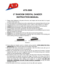
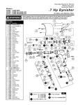
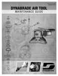
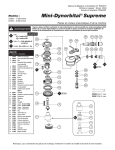
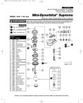
Parts Page Reorder No. PD05•21
Effective May, 2005
Supersedes PD05•02
For Serial No. 4G1255 and Higher
Right Angle Mini-Orbital Sander
Air Tool Manual – Safety, Operation and Maintenance
SAVE THIS DOCUMENT, EDUCATE ALL PERSONNEL
Model:
58035 – 15,000 RPM
58037 – 12,000 RPM
58038 – 12,000 RPM
WARNING
Read and understand this tool manual before operating your air tool. Follow all safety rules for the protection of operating personnel
as well as adjacent areas. Always operate, inspect and maintain this tool in accordance with the American National Safety Institute
(ANSI) Safety Code for Portable Air Tools – B186.1. For additional safety information, refer to – ANSI B7.1, Code of Federal Regulation
– CFR 29 Part 1910, European Committee for Standards (EN) Hand Held Non-Electric Power Tools – Safety Requirements and
applicable State and Local Regulations.
SAFETY LEGEND
WARNING
Read and understand tool manual before
work starts to reduce risk of injury to
operator, visitors, and tool.
WARNING
Eye protection must be worn at all times,
eye protection to conform to ANSI Z87.1.
WARNING
Respiratory protection to be used when exposed to
contaminants that exceed the applicable threshold
limit values required by law.
WARNING
Practice safety requirements. Work alert,
have proper attire, and do not operate tools under
the influence of alcohol or drugs.
WARNING
Ear protection to be worn when exposure to sound,
exceeds the limits of applicable Federal, State or
local statues, ordinances and/or regulations.
WARNING
Air line hazard, pressurized supply lines and flexible
hoses can cause serious injury. Do not use damaged,
frayed or deteriorated air hoses and fittings.
SAFETY INSTRUCTIONS
Carefully Read all instructions before operating or servicing any Dynabrade® Abrasive Power Tool.
Products offered by Dynabrade are not to be modified, converted or otherwise altered from the original design without expressed written
consent from Dynabrade, Inc.
Tool Intent: Right Angle Mini-Orbital Sander is ideal for finesse sanding.
Do Not Use Tool For Anything Other Than Its Intended Applications.
This power tool is not intended for use in potentially explosive atmospheres and is not insulated against contact with electrical power.
Training: Proper care, maintenance, and storage of your tool will maximize their performance.
• Employer's Responsibility – Provide Right Angle Mini-Orbital Sander operator with safety instructions and training for safe use of tools and accessories.
Accessory Selection:
• Abrasive/accessory RPM (speed) rating MUST be approved for AT LEAST the tool RPM rating.
• Before mounting an accessory, visually inspect for defects. Do not use defective accessories.
• Use only recommended accessories. See back page of manual and Dynabrade Literature.
• Follow tool specifications before choosing size and type of accessory.
• Only use recommended fittings and air line sizes. Air supply hoses and air hose assemblies must have a minimum working pressure rating of 150 PSIG
(10 Bars, g) or 150 percent of the maximum pressure produced in the system, whichever is higher. (See tool Machine Specifications table.)
OPERATING INSTRUCTIONS
Warning: Always wear eye protection. Operator of tool is responsible for following: accepted eye, face, respiratory, hearing and body protection.
Caution: Hand, wrist and arm injury may result from repetitive work, motion and overexposure to vibration.
Caution: Be sure that any loose clothing, hair and all jewelry is properly restrained.
• Install air fitting into inlet bushing of tool. Important: Secure inlet bushing of tool with a wrench before attempting to install the air fitting to avoid
damaging valve body housing.
• Connect air source, depress throttle lever.
• BEFORE MOUNTING AN ACCESSORY, after all tool repairs and whenever a Right Angle Mini-Orbital Sander is issued for use, check tool OPM (speed)
with tachometer with air pressure set at 90 PSIG while the tool is running. This tool is an orbital tool, checking the OPM requires either a strobe or
magnetic tachometer. If tool is operating at a higher speed than the RPM marked on the tool housing, or operating improperly, the tool must be serviced
and corrected before use.
Caution:Tool RPM / OPM must never exceed abrasive/accessory RPM / OPM rating. Check accessory manufacturer for details on maximum operating
speed or special mounting instructions.
• With power source connected at the air tool relieve hose of air pressure and disconnect tool from air supply when changing recommended accessories.
• Connect air tool to power source. Be careful NOT to depress throttle lever in the process.
Do not expose air tool to inlet pressure above 90 PSIG or (6.2 Bars).
Caution: After installing the accessory, before testing or use and/or after reassembling tool, the Right Angle Mini-Orbital Sander must be started at a reduced
speed to check for good balance. Gradually increase tool speed. DO NOT USE if tool vibration is excessive. Correct cause, and retest to
insure safe operation.
• Use only appropriately sized abrasive sanding discs properly secured to the backing pad provided with the air sander. Ensure that self-fixing sanding
discs are mounted concentrically.
• Make sure that work area is uncluttered, and visitors are at a safe range from the tools and debris. Potentially explosive atmospheres can be caused
by dust and fumes resulting from sanding or grinding. Always use dust extraction or suppression systems which are suitable for the material
being processed.
• Proceed with caution in unfamiliar surroundings. Hidden hazards may exist, such as electricity or other utility lines.
• Air tools are not intended for use in explosive atmospheres and are not insulated for contact with electric power sources.
• Use a vise or clamping device to hold work piece firmly in place.
• Work may generate hazardous dust.
• Do not apply excessive force on tool or apply “rough” treatment to it.
• Always work with a firm footing, posture and proper lighting.
• Ensure that sparks and debris resulting from work do not create a hazard.
• This tool is front exhaust. Exhaust may contain lubricants, vane material, bearing grease, and other materials flushed thru the tool.
Report to your supervisor any condition of the tool, accessories, or operation you consider unsafe.
Air System
Filter
Regulator
LUBRICATOR SETTING
Lubricator
1 DROP/MIN.
20 SCFM
Air Flow
➤
➤
Closed Loop Pipe System
(Sloped in the direction of air flow)
90 PSIG
(6.2 Bar)
To Tool Station
Regulator
Refrigerated
Air Dryer
Lubricator
➤
➤
Filter
• Ideally the air supply should be free from moisture.
Incorporating a refrigerated air dryer after the
compressor and drain valves at each tool station
(as shown) further reduces moisture from
condensation in the air supply.
Ball
Valve
Drain
Valve
➤
Drain
Valve
Air Hose
Ball
Valve
➤
• Dynabrade Air Power Tools are designed to
operate at 90 PSIG (6.2 Bar/620 kPa) maximum
air pressure at the tool inlet, when the tool is
running. Use recommended regulator to control
air pressure.
Air Flow
Air Tool
90 PSIG MAX
(6.2 Bar)
Drain Valve
Air Compressor
and Receiver
Maintenance Instructions
Important: A preventative maintenance program is recommended whenever portable power tools are used. The program should include inspection of air
supply lines, air line pressure, proper lubrication and repair of tools. See Preventative Maintenance Schedule on pg 7.
Refer to ANSI B186.1 for additional maintenance information.
• Use only genuine Dynabrade replacement parts to insure quality. To order replacement parts, specify Model#, Serial# and RPM of your air tool.
• It is strongly recommended that all Dynabrade rotary vane air tools be used with a Filter-Regulator-Lubricator to minimize the possibility of misuse due
to unclean air, wet air or insufficient lubrication. Dynabrade recommends the following: 11405 Air Filter-Regulator-Lubricator (FRL) – Provides accurate
air pressure regulation and two stage filtration of water contaminants. Operates 40 SCFM @ 100 PSIG with 3/8" NPT female ports.
• Dynabrade recommends one drop of air lube per minute for each 20 SCFM (example: if the tool specification states 40 SCFM, set the drip rate on the
filter-lubricator to 2 drops per minute). Dynabrade Air Lube (P/N 95842: 1 pt 473 ml) is recommended.
• Lubricate wick system through the angle gear oil fitting with 2-3 plunges for every 24 hours of use, to achieve maximum gear life.
Important: Use only 95848 Gear Oil dispensed with the 95581 Gun. DO NOT contaminate the wick with any other oil or grease product.
Routine Preventative Maintenance:
• Check free speed of Right Angle Mini-Orbital Sander using a tachometer on a regular basis.
• Mineral spirits are recommended when cleaning the tool and parts. Do not clean tool or parts with any solvents or oils containing acids, esters,
ketones, chlorinated hydrocarbons or nitro carbons.
• DO NOT clean or maintain tools with chemicals that have a low flash point (example: WD-40®).
• A Motor Tune-Up Kit (P/N 96179) is available which includes high wear and medium wear motor parts.
• All tool labels must be kept legible at all times. User is responsible for maintaining specification information i.e.:
Model #, S/N, and RPM. (See Assembly Breakdown)
• Blow air supply hose out prior to initial use.
• Visually inspect air hoses and fittings for frays, visible damage and signs of deterioration. Replace damaged or worn components.
• Refer to Dynabrade's Warning/Safety Operating Instructions Tag (Reorder No. 95903) for safety information.
After maintenance is performed on tool, add a few drops of Dynabrade Air Lube (P/N 95842) to the air line and start the tool a few times to lubricate air motor.
Check for excessive tool vibration.
Handling and Storage:
•
•
•
•
•
Use of tool rests, hangers and/or balancers is recommended.
Protect tool inlet from debris (see Notice below).
DO NOT carry tool by air hose, or near the tool throttle lever.
Protect abrasive accessories from exposure to water, solvents, high humidity, freezing temperature and extreme temperature changes.
Store accessories in protective racks or compartments to prevent damage.
Machine Specifications
Model
Number
Motor
HP (W)
Motor
RPM
Sound
Level
Maximum Air Flow
CFM/SCFM (LPM)
Air Pressure
PSIG (Bars)
Weight
Pound (kg)
Length
Inch (mm)
Height
Inch (mm)
58035
.4 (298)
15,000
85
3/21 (595)
90 (6.2)
1.63 (.74)
5-7/16 (138)
3-11/16 (94)
58037
.4 (298)
12,000
85
3/20 (566)
90 (6.2)
1.63 (.74)
5-7/16 (138)
3-3/4 (96)
58038
.4 (298)
12,000
85
3/20 (566)
90 (6.2)
1.63 (.74)
5-7/16 (138)
4 (104)
Additional Specifications: Air Inlet Thread 1/4" NPT • Hose I.D. Size 1/4" or 8mm
Notice
All Dynabrade motors use the highest quality parts and materials available and are machined to exacting tolerances. The failure of quality pneumatic motors
can most often be traced to an unclean air supply or the lack of lubrication. Air pressure easily forces dirt or water contained in the air supply into motor
bearings causing early failure. It often scores the cylinder walls and the rotor blades resulting in limited efficiency and power. Our warranty obligation is
contingent upon proper use of our tools and cannot apply to equipment which has been subjected to misuse such as unclean air, wet air or a lack of
lubrication during the use of this tool.
One Year Warranty
Following the reasonable assumption that any inherent defect which might prevail in a product will become apparent to the user within one year from the date
of purchase, all equipment of our manufacture is warranted against defects in workmanship and materials under normal use and service. We shall
repair or replace at our factory, any equipment or part thereof which shall, within one year after delivery to the original purchaser, indicate upon our
examination to have been defective. Our obligation is contingent upon proper use of Dynabrade tools in accordance with factory recommendations,
instructions and safety practices. It shall not apply to equipment which has been subject to misuse, negligence, accident or tampering in any way so as to
affect its normal performance. Normally wearable parts such as bearings, contact wheels, rotor blades, etc., are not covered under this warranty.
3
Right Angle Mini-Orbital Sander
Complete Assembly
Models:
58035 – 15,000 RPM
58037 – 12,000 RPM
58038 – 12,000 RPM
Index Key
No. Part #
1
47
48
54088
54018
54031
97175
95615
30701
30721
30709
30700
97174
30702
30705
97172
97173
30703
02035
30704
01486
54520
97118
97117
97116
Gear
02597
02623
02044
02045
02052
02033
02041
01040
01728
01461
01547
Pinion
02598
02624
02649
54529
01478
50767
01479
02037
01480
01476
02676
02696
02679
01448
01462
01449
95558
12132
30710
30712
30713
95730
01469
49
50
51
52
53
54
55
01024
01464
01472
01468
96065
53190
01494
2
3
4
5
6
7
8
9
10
11
12
13
14
15
16
17
18
19
20
21
22
23
24
25
26
27
28
29
30
31
32
33
34
35
36
37
38
39
40
41
42
43
44
45
46
Description
Pad - Mdl: 58035
Pad - Mdl: 58037
Pad - Mdl: 58038
Screw (4)
Roloc® Shell
Plate - Mdl: 58035, 37
Plate - Mdl: 58038
Boot Clamp
Boot
Screw
Balancer Shaft
Bearing (2)
Snap Ring
Set Screw
Counterweight
Lock Ring
Shaft
Felt Silencer
Bearing
Shim
Shim
Shim
33
17 N•m
W1
T
32
30
29
27
26
A4
25
31
23
28
T
•m
34 N
A8
W1
22
21
40
34
20
38
37 O1
36
18
35
17
16
15
A8
13
T
23 N•m
55
O1
51
48
46
T
53
49
14
Mdl: 58035
Mdl: 58037, 58038
Bearing
Shim (3/pkg.)
Front Bearing Plate
Pin (2)
Spacer
Rotor
Blades (4/Pkg.)
Cylinder
Rear Bearing Plate
Bearing
Shield
Throttle Lever
Safety Lock Lever
Valve Stem
Retaining Ring
Pin
Housing - Mdl: 58035
Housing - Mdl: 58037
Housing - Mdl: 58038
O-Ring
Speed Regulator
Assembly
O-Ring
Seal
Tip Valve
Spring
O-Ring
Block Plate
Inlet Bushing
41
24
19
Mdl: 58035
Mdl: 58037, 58038
Bottom Wick
Top Wick
Housing
Needle Bearing
Gear Oil Plate
Gear Oil Fitting
Felt Silencer (2)
Lock Nut
Collar
39
34
47
23 N•m
54
12
11 A8
50
45
10
A8
52
44
A8
42
43
9
8
7
Optional Accessory
A8
6
A8
95745 Flow Control Assembly (1/4" NPT)
5
4
2
3
1
4
KEY
O
Oil: O1 = Air Lube
W
Wicking: W1 = Gear Oil
A
Adhesive: A4 = Loctite #680
A8 = Loctite #567
T
Torque: N•m x 8.85 = In. - lbs.
Disassembly/Assembly Instructions - Right Angle Tools
Important: Manufacturer’s warranty is void if tool is disassembled before warranty expires.
Please refer to parts breakdown for part identification.
Motor Disassembly:
1. Shut the air supply and disconnect the sander from the air supply hose. Important: Hold the air inlet adapter securely with a wrench before removing the air fitting so as
to prevent damage to the composite housing.
2. Secure the motor housing in a vise by using the 52296 Repair Collar to provide protection for the housing. Position the tool so that the angle head is pointing up.
3. Use a 34mm or an adjustable wrench to remove the 01461 Lock Nut by turning it clockwise.
4. Pull the motor assembly out of the motor housing.
5. Fasten the 96346, 2" Bearing Separator around the portion of the 01476 Cylinder that is closest to the 02676 Rear Bearing Plate.
6. Place the bearing separator on the table of the arbor press so that the pinion gear end of the rotor is pointing toward the floor.
7. Use a 3/16" dia. flat end drive punch as a press tool and position it on the rotor shaft. Press the rotor out of the 02696 Bearing. The 02696 Bearing can be removed from the
02676 Bearing Plate with the 96210 Bearing Removal Tool and the 96232 Arbor Press (#2).
8. Secure the body of the rotor in a vise with bronze or aluminum jaws so that the pinion gear is pointing up.
9. Use a wrench to remove the pinion gear from the rotor by turning it counterclockwise.
10. Pull the 01478 Front Bearing Plate with bearing off the rotor.
11. Push the 02649 Bearing out of the front bearing plate and remove the shims.
12. Slip the 01479 Spacer off the rotor.
Motor Disassembly Complete.
Orbital Head Disassembly:
1.
2.
3.
4.
Shut the air supply and disconnect the sander from the air supply hose.
Remove the pad.
Use a Phillips® screwdriver to remove the 97175 Screws (4).
Use a sharp utility knife to cut through and remove the 30709 Boot Clamp. Important: Cut the clamp carefully so as to prevent personal injury and damage
to the 30700 Boot.
5. Pull the 30700 Boot from the 02052 Housing.
6. Hold the 30703 Counterweight stationary with a 19mm open-end wrench. Use a Phillips® screwdriver to loosen the 97174 Screw and remove the 30702 Balancer Shaft.
7. Use a 5/64" (2mm) slotted screw, screwdriver to remove the 97172 Snap Ring.
8. Use the 96210 Bearing Removal Tool and the 96232 Arbor Press (#2) to push the 30705 Bearings (2) out of the balancer shaft.
9. Use a 2mm Hex Key to remove the 97173 Set Screw and the 30703 Counterweight.
Orbital Head Disassembly Complete.
Right Angle Housing Disassembly:
1. Shut the air supply and disconnect the sander from the air supply hose.
2. Secure the 30710 / 30712 Housing in a vise by using the 52296 Repair Collar to provide protection for the housing. Position the housing so that the 02035 Lock
Ring is facing up.
3. Use the 50971 Lock Ring Tool to remove the 02035 Lock Ring, by turning it counterclockwise.
4. Grasp the shaft to pull the shaft, the 54520 Bearing, the gear and the shims out of the housing.
5. The bearing and gear can be pressed off the spindle with the 96232, Arbor Press (#2).
6. If necessary the 02033 Needle Bearing can be removed by using a 5/16" dia. flat end drive punch to push the 02041 Gear Oil Plate, and 01041 Gear Oil Fitting out
of the 02052 Housing.
Right Angle Housing Disassembly Complete.
Valve Disassembly:
1.
2.
3.
4.
Use the 52296 Repair Collar to securely hold the motor housing in a vise so that the inlet adapter is pointing up.
Remove the valve components by loosening the inlet adapter. Remove the 01468 Spring, 01472 Tip Valve, and 01464 Seal.
Reposition the motor housing in the vise so that the throttle lever, and the 12132 Pin are accessible. Remove the pin and lever by using a 2.5mm dia. drive punch.
Use retaining ring pliers to remove the 95558 Retaining Ring and push the 01469 Speed Regulator Assembly out of the motor housing.
Valve Disassembly Complete.
Important: Clean and inspect parts for wear or damage before assembling.
Valve Assembly:
1.
2.
3.
4.
Install the 01469 Speed Regulator Assembly into the motor housing, and secure it in place with the 95558 Retaining Ring.
Use the 52296 Repair Collar to securely hold the motor housing in a vise so that the air inlet is pointing up.
Insert the 01449 Valve Stem into the speed regulator assembly so that the hole in the valve stem aligns with the air inlet hole in the motor housing.
Install the 01464 Seal so that it lays flat. Use a needle nose pliers to grasp the nylon portion of the 01472 Tip Valve and install it so that the metal pin fits into the hole
of the 01449 Valve Stem.
5. Install the 01468 Spring so that the smaller end fits against the back of the tip valve.
6. Refer to the parts breakdown for part identification and the sequence of assembly. Apply a small amount of Loctite® #567 (or equivalent) to the male threads of the
inlet adapter and tighten the inlet adapter. (Torque to 23 N-m/200 in. lbs.)
Valve Body Assembly Complete.
Motor Assembly:
1.
2.
3.
4.
5.
Secure the body of the rotor in a vise with bronze or aluminum jaws so that the threaded end is pointing up.
Slip the 01479 Spacer onto the 02037 Rotor.
Select .003 (.08mm) thick shims from the 54529 Shim Pack and place these into the 01478 Front Bearing Plate.
Install the 02649 Bearing into the front bearing plate and slip the bearing/plate assembly onto the rotor.
Install the pinion onto the rotor, making it hand tight.
(continued on next page)
5
Disassembly/Assembly Instructions - Right Angle Tools
6. Check the clearance between the rotor and the bearing plate with a .001 thick feeler gauge. Clearance should be .001” to .0015” (0.03-0.04mm). If it’s necessary, readjust
clearance by repeating steps 3-5 with different thickness shims.
7. Once the proper rotor/plate clearance is achieved wrench tighten the pinion. (Torque to 17N·m/150 in. lbs.)
8. Apply the 95842 Dynabrade Air Lube (10W/NR or equivalent) to the 01480 Blades and install them onto the rotor.
9. Use the 96216 Bearing Press Tool so that it pushes against the outer race of the 02696 Bearing and install it into the 02676 Rear Bearing Plate with the arbor press.
10. Place the pinion on the tool plate of the arbor press so that the rear portion of the rotor is pointing up.
11. Install the 01476 Cylinder so that it rests against the 01478 Bearing Plate. Note: Make sure that the air inlet passage of the cylinder will properly aligned with the air inlet
passage in the 02676 Bearing Plate.
12. Use the 96216 Bearing Press Tool so that it pushes against the inner race of the 02696 Bearing and install the rear bearing/plate assembly onto the rotor with the
arbor press. Important: Carefully press the rear bearing/plate assembly onto the rotor until it touches the 01476 Cylinder. A “snug” fit should exist between the bearing
plates and cylinder. If it is too tight the rotor will not turn freely and will cause damage to the bearings. If it is too loose the proper bearing preload will not be achieved.
13. Apply a small amount of grease to the seal of the 02696 Rear Bearing and place the 02679 Shield against the seal of the bearing.
14. Install the motor assembly into the housing so that the air passage node of the rear bearing plate aligns with the air passage notch inside the housing.
15. Apply a small amount of Loctite® #567 (or equivalent) to the threads of the motor housing and use a 34mm (or an adjustable wrench) to connect the angle head assembly
to the motor housing. (Torque to 34 N-m/300 in. lbs.)
Motor Assembly Complete.
Right Angle Housing Assembly:
1. Press the 01041 Gear Oil Fitting into the 02041 Gear Oil Plate.
2. Carefully apply two drops of Loctite® #680 (or equivalent) to the recessed area of the
02052 Housing
02033 Needle Bearing
02052 Housing and press the gear oil plate along with gear oil fitting into the housing.
(Allow 30 minutes for the adhesive to cure.)
3. Press the 02033 Needle Bearing into the housing.
02041 Gear Oil Plate
4. Position the 96239 Bearing Press Tool so that it rests against the inner race of the
54520 Bearing and press the bearing onto the spindle.
01040 Gear Oil Fitting
5. Align the hex shaped I.D. area of the gear with that of the spindle and press the gear into place.
6. Apply a small amount of Loctite® #567 (or equivalent) to the mating threads of the 02052
Housing. Connect these parts while being aware of the right and left hand threads.
2 Drops of Loctite
7. Place the 52296 Repair Collar around the motor housing and position the tool in a vise so
that the angle housing end of the tool is pointing up.
8. Use a 34mm or adjustable wrench on the 01461 Lock Nut while holding the angle housing
stationary with one hand. Note: The throttle lever can be positioned in 360˚ to the desired location.
Allow for additional rotation when tightening the lock nut. (Torque to 34 N-m/300 in. lbs.)
9. Reposition the tool assembly in the vise so that the opening in the angle housing, for the 02035 Lock Ring is facing up.
10. Soak the wicks in the 95848 Gear Oil before installing them into the 02052 Housing. Install the top wick first followed by the bottom wick. Position truncated side of each
wick toward the end of the pinion gear.
11. Install the 30704 Shaft into the angle housing. Apply a slight amount of pressure down on the spindle while rotating it back and forth checking for the proper backlash or fit
between the gears. A slight amount of backlash or clearance should exist between the bevel and pinion gears. When a tight fit exist, then add shims as needed placing the
required thickness of shims between the outer race of the 54520 Bearing and the bearing seat in the housing.
12. Place (1) 01486 Felt Silencer into the 02035 Lock Ring, and apply a small amount of Loctite® #567 (or equivalent) to the threads of the 02035 Lock Ring. Use the
50971 Lock Ring Wrench to install the lock ring onto the 02052 Housing. (Torque to 23 N-m/200 in. lbs.)
Right Angle Housing Assembly Complete.
Orbital Head Assembly:
1.
2.
3.
4.
5.
6.
7.
Install the 30703 Counterweight onto the 30704 Shaft, aligning the screw hole with the pilot hole in the shaft.
Apply a small amount of the Loctite® #567 (or equivalent) to the threads of the 97173 Set Screw.
Use a 2mm hex key to install the 97173 Set Screw into the 30703 Counterweight and secure the counterweight to the 30704 Shaft.
Use the raised outer diameter of the 96216 Bearing Press Tool and the 96232 Arbor Press (#2) to press the 30705 Bearings (2) into the 30702 Balancer Shaft.
Install the 97172 Snap Ring into the 30702 Balancer Shaft.
Install the balancer shaft assembly onto the 30704 Shaft.
Apply a small amount of the Loctite® #567 (or equivalent) onto the threads of the 97174 Screw. Hold the 30703 Counterweight stationary with a 19mm open-end wrench.
Use a Phillips® screwdriver to tighten the 97174 Screw into the 30704 Shaft.
8. Install the 30700 Boot and the 30701 Plate, aligning the screw holes.
9. Install the 97175 Screws (4) securely.
10. Install the 30709 Boot Clamp around the 30700 Boot and use a HEAT GUN to shrink-fit the clamp, securing the boot to the 02052 Housing.
11. Install the pad.
Orbital Head Assembly Complete.
Tool Assembly Complete. Please allow 30 minutes for adhesives to cure before operating tool.
Important: Before operating, place 2-3 drops of Dynabrade Air Lube (P/N 95842) directly into air inlet with throttle lever depressed. Operate tool for 30 seconds to determine if tool
is operating properly and to allow lubricating oils to properly penetrate motor. Motor should now be tested for proper operation at 90 PSIG. If motor does not operate properly or
operates at a higher RPM than marked on the tool, the tool should be serviced to correct the cause before use.
Loctite ® is a registered trademark of Loctite Corp.
6
Preventative Maintenance Schedule
For All Right Angle Mini-Orbital Sander
This service chart is published as a guide to expectant life of component parts. The replacement levels are based on average tool
usage over one year. Dynabrade Inc. considers one year usage to be 1,000 hours.
Parts Common to all Models:
LEGEND
T
X
Included in Tune-up Kit
Type of wear, no other
comments apply.
L
Easily lost. Care during
assembly/disassembly.
D
Easily damaged during
assembly/disassembly.
R
Replace each time tool is
disassembled.
96179 – Motor Tune-Up Kit
Index Part
# Number
1 See Note
2 97175
3 30701
4 30709
5 30700
6 97174
7 30702
8 30705
9 97172
10 97173
11 30703
12 02035
13 30704
14 01486
15 54520
16 97118
17 97117
18 97116
19 See Note
20 02044
21 02045
22 See Note
23 02033
24 02041
25 01040
26 01728
27 01461
28 01547
29 See Note
30 02649
31 54529
32 01478
33 50767
34 01479
35 02037
36 01480
37 01476
38 02676
39 02696
40 02679
41 01448
01462
42 01449
43 95558
44 12132
45 See Note
46 95730
47 01469
48 01024
49 01464
50 01472
51 01468
52 96065
53 53190
53 01494
Description
Pads
Screw
Plate
Boot Clamp
Boot
Screw
Balancer Shaft
Bearing
Snap Ring
Set Screw
Counterweight
Lock Ring
Shaft
Felt Silencer
Bearing
Shim
Shim
Shim
Gear
Bottom Wick
Top Wick
Housing
Needle Bearing
Gear Oil Plate
Gear Oil Fitting
Felt Silencer
Lock Nut
Collar
Pinion
Bearing
Shim (3/pkg.)
Front Bearing Plate
Pin
Spacer
Rotor
Blades (4/Pkg.)
Cylinder
Rear Bearing Plate
Bearing
Shield
Throttle Lever
Safety Lock Lever
Valve Stem
Retaining Ring
Pin
Housing
O-Ring
Speed Regulator Assy.
O-Ring
Seal
Tip Valve
Spring
O-Ring
Block Plate
Inlet Bushing
Number High Wear Medium Wear Low Wear
Required
100%
70%
30%
1
4
X
1
X
1
X
1
X
1
1
2
X
1
L
1
X
1
1
1
1
T
1
T
1
T
1
T
1
T
1
X
1
T
1
T
1
1
X
1
X
1
X
2
T
1
X
1
X
1
X
1
T
1
T
1
X
2
X
1
X
1
1
T
1
X
1
X
1
T
1
T
1
X
1
X
1
T
1
T
1
T
1
1
T
1
T
1
T
1
T
1
T
1
T
1
T
1
1
Non-Wear
10%
X
X
X
X
X
X
X
X
X
X
Note: Pads are a consumable item. They are application sensitive. Their expectant life will vary depending on the
specific work application and work habit of the operator.
7
Optional Accessories
52296 Repair Collar
• Specially designed collar for use in vise to prevent
damage to valve body of tool during disassembly/assembly.
96179 Motor Tune-Up Kit
• Includes assorted parts to help
maintain and repair motor.
Dynabrade Angle Gear Oil
• Specifically formulated to saturate wick system in right
angle gear head.
• Easy to apply using Dynabrade P/N 95541 Oil Gun.
Apply 3 plunges every 8 hours of operation into tools
lubrication fitting.
95848: 2 oz. tube
95849: 10 oz. tube
Dynaswivel ®
• Swivels 360° at two locations which allows an
air hose to drop straight to the floor, no matter
how the tool is held.
94300 1/4" NPT.
Dynabrade Air Lube
• Formulated for pneumatic equipment.
• Absorbs up to 10% of its weight in water.
• Prevents rust and formation of sludge.
• Keeps pneumatic tools operating longer
with greater power and less down time.
95842: 1pt. (473 ml)
95843: 1gal. (3.8L)
Special Repair Tools
Note: Mentioned In Assembly/Disassembly
96216
96232
96346
96210
96239
52296
50971
Bearing Press Tool
(#2) Arbor Press
(2") Bearing Separator
Bearing Removal Tool
Bearing Press Tool
Repair Collar
Lock Ring Tool
Special Greasing Instructions
Expect a
gear life of
500 hours
minimum,
with proper
lubrication.
Apply 3 plunges
into lubrication
fitting every
24 hours of
operation.
Lubricate wick system through the angle gear oil fitting with 2-3 plunges for every 24
hours of use, to achieve maximum gear life.
Important: Use only the recommended angle gear oil for the wick system.
Do not contaminate the wick with any other oil or grease product.
(Order 95848 Gear Oil and 95541 Gun)
02052 Housing
01040 Gear Oil Fitting
Reference Contact Information
1. American National Safety Institute – ANSI
25 West 43rd Street
Forth Floor
New York, NY 10036
Tel: 1 (212) 642-4900
Fax: 1 (212) 398-0023
3. European Committee for Standardization
Rue de Stassart 36
B - 1050 Brussels, Belgium
2. Government Printing Office – GPO
Superintendent of Documents
Attn. New Orders
P.O. Box 371954
Pittsburgh, PA 15250-7954
Tel: 1 (202) 512-1803
Visit Our Web Site: www.dynabrade.com
®
Email: [email protected]
DYNABRADE
DYNABRADE, INC., 8989 Sheridan Drive • Clarence, NY 14031-1490 • Phone: (716) 631-0100 • Fax: 716-631-2073 • International Fax: 716-631-2524
DYNABRADE EUROPE S.àr.l.,
Zone Artisanale • L-5485 Wormeldange—Haut, Luxembourg • Telephone: 352 76 84 94 1 • Fax: 352 76 84 95 1
© DYNABRADE, INC., 2005
PRINTED IN USA
PD05.02_01/05