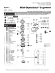
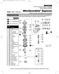
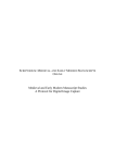
1
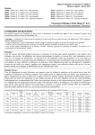
AUTOMOTIVE
Parts Page Reorder No. APD03•02
Effective January, 2003
Supersedes APD02•13
Dynorbital-Spirit ™
For Serial No. 3B1000B and Higher
12,000 RPM Air Powered Random Orbital Sander
Air Tool Manual – Safety, Operation and Maintenance
SAVE THIS DOCUMENT, EDUCATE ALL PERSONNEL
Models:
3/8" Orbit
21000
21001
21004
21005
21006
21009
21010
21011
21014
21015
21016
21019
21060
21063
3/16" Orbit
21020
21021
21024
21025
21026
21029
21030
21031
21034
21035
21036
21039
21061
21064
3/32" Orbit
21040
21041
21044
21045
21046
21049
21050
21051
21054
21055
21056
21059
21062
21065
FOR COMPLETE MODEL DESCRIPTION REFERENCE PAGE 6.
P
WARNING
Read and understand this tool manual before operating your air tool. Follow all safety rules for the protection of operating personnel
as well as adjacent areas. Always operate, inspect and maintain this tool in accordance with the American National Safety Institute
(ANSI) Safety Code for Portable Air Tools – B186.1. For additional safety information, refer to Safety Requirements for the Use, Care
and Protection of Abrasive Wheels – ANSI B7.1, Code of Federal Regulation – CFR 29 Part 1910, European Committee for Standards
(EN) Hand Held Non-Electric Power Tools – Safety Requirements and applicable State and Local Regulations.
SAFETY LEGEND
WARNING
Read and understand tool manual before
work starts to reduce risk of injury to
operator, visitors, and tool.
WARNING
Eye protection must be worn at all times,
eye protection to conform to ANSI Z87.1.
WARNING
Respiratory protection to be used when exposed to
contaminants that exceed the applicable threshold
limit values required by law.
WARNING
Practice safety requirements. Work alert,
have proper attire, and do not operate tools under
the influence of alcohol or drugs.
WARNING
Ear protection to be worn when exposure to sound,
exceeds the limits of applicable Federal, State or
local statues, ordinances and/or regulations.
WARNING
Air line hazard, pressurized supply lines and flexible
hoses can cause serious injury. Do not use damaged,
frayed or deteriorated air hoses and fittings.
SAFETY INSTRUCTIONS
Carefully Read all instructions before operating or servicing any Dynabrade® Abrasive Power Tool.
Products offered by Dynabrade are not to be modified, converted or otherwise alerted from the original design without expressed written consent from Dynabrade, Inc.
Tool Intent: Dynorbital-Spirit™ Random Orbital Sander is used for sanding and finishing a variety of materials including wood, metal, plastic, fiberglass, solid surfaces,
composites, rubber, glass and stone.
Do Not Use Tool For Anything Other Than Its Intended Applications.
Training: Proper care, maintenance, and storage of your tool will maximize its performance.
• Employer's Responsibility – Provide Dynorbital-Spirit™ operators with safety instructions and training for safe use of tools and accessories.
Accessory Selection:
• Abrasive/accessory RPM (speed) rating MUST be approved for AT LEAST the tool RPM rating.
• Before mounting an accessory, visually inspect for defects. Do not use defective accessories.
• Follow tool specifications before choosing size and type of accessory.
• Only use recommended fittings and air line sizes. Air supply hoses and air hose assemblies must have a minimum working pressure rating of 150 PSIG (10 bars, g) or 150
percent of the maximum pressure produced in the system, whichever is higher. (See Tool Machine Specifications Table.)
• DO NOT use – ......................................................
OPERATING INSTRUCTIONS
Warning: Always wear eye protection. Operator of tool is responsible for following: accepted eye, face, respiratory, hearing and body protection.
Caution: Hand, wrist and arm injury may result from repetitive work, motion and overexposure to vibration.
(continued on next page)
OPERATING INSTRUCTIONS (continued)
• Keep hand and clothing away from working end of the air tool.
Operation: Be sure that any loose clothing, hair and all jewelry is properly restrained.
• Secure inlet bushing on air tool with a wrench before attempting to install the air fitting to avoid damaging housing assembly.
• Check tool RPM (speed) with tachometer with air pressure set at 90 PSIG while the tool is running. If tool is operating at a higher speed than the RPM marked on the tool
housing, or operating improperly, the tool must be serviced and corrected before use.
Caution: Tool RPM must never exceed abrasive/accessory RPM rating. Check accessory manufacturer for details on maximum operating speed or special
mounting instructions.
• With power source disconnected from air tool, mount recommended accessory into collet assembly.
• Connect air tool to power source. Be careful NOT to depress throttle lever in the process. Do not expose air tool to inlet pressure above 90 PSIG or (6.2 Bars).
Caution: After installing the accessory, before testing or use and/or after assembling tool, the Dynorbital-Spirit™ must be started at a reduced speed to check for good
balance. Gradually increase tool speed. DO NOT USE if tool vibration is excessive. Correct cause, and retest to insure safe operation.
• Make sure that work area is uncluttered, and visitors are at a safe range from the tools and debris.
• Use a vise or clamping device to hold work piece firmly in place.
• Do not apply excessive force on tool or apply “rough” treatment to it.
• Always work with a firm footing, posture and proper lighting.
Report to your supervisor any condition of the tool, accessories, or operation you consider unsafe.
Air System
Regulator
Filter
LUBRICATOR SETTING
Lubricator
1 DROP/MIN.
20 SCFM
90 PSIG
(6.2 Bar)
Air Flow
➤
➤
Closed Loop Pipe System
(Sloped in the direction of air flow)
To Tool Station
Regulator
Refrigerated
Air Dryer
Lubricator
➤
➤
Filter
Ball
Valve
Drain
Valve
Air Hose
Ball
Valve
➤
Drain
Valve
➤
Air Flow
Coupler
Air Tool
Air Compressor
and Receiver
90 PSIG MAX
(6.2 Bar)
• Dynabrade Air Power Tools are designed to
operate at 90 PSIG (6.2 Bar/620 kPa) maximum
air pressure at the tool inlet, when the tool is
running. Use recommended regulator to control
air pressure.
Drain Valve
2
• Ideally the air supply should be free from moisture.
Incorporating a refrigerated air dryer after the
compressor and drain valves at each tool station
(as shown) further reduces moisture from
condensation in the air supply.
Maintenance Instructions
Important: A Preventative Maintenance Program is recommended whenever portable power tools are used.
• Use only genuine Dynabrade replacement parts to insure quality. To order replacement parts, specify Model#, Serial# and RPM of your air tool.
• It is strongly recommended that all Dynabrade rotary vane air tools be used with a Filter-Regulator-Lubricator to minimize the possibility of misuse due
to unclean air, wet air or insufficient lubrication. Dynabrade recommends the following: 11405 Air Filter-Regulator-Lubricator (FRL) – Provides accurate
air pressure regulation and two stage filtration of water contaminants. Operates 40 SCFM/1,133 LPM @ 100 PSIG with 3/8" NPT female ports.
• Dynabrade recommends one drop of air lube per minute for each 20 SCFM (example: if the tool specification states 40 SCFM, set the drip rate on the
filter-lubricator to 2 drops per minute). Dynabrade Air Lube (P/N 95842: 1 pt 473 ml) is recommended.
Routine Preventative Maintenance: Check free speed of Dynorbital-Spirit™ using a tachometer.
• Mineral spirits are recommended when cleaning the tool and parts. Do not clean tool or parts with any solvents or oils containing acids, esters,
ketones, chlorinated hydrocarbons or nitro carbons.
• DO NOT clean or maintain tools with chemicals that have a low flash point (example: WD-40®).
• A Drop-In Motor and Tune-Up Kit are available, see specific kit number on page 9.
• Air tool stampings must be kept legible at all times, if not, reorder and replace. User is responsible for maintaining specification information i.e.:
Model #, S/N, and RPM.
• Blow air supply hose out prior to initial use.
• Visually inspect air hoses and fittings for frays, visible damage and signs of deterioration. Replace damaged or worn components.
• Refer to Dynabrade's Warning/Safety Operating Instructions Tag (Reorder No. 95903) for safety information.
After maintenance is performed on tool, add a few drops of Dynabrade Air Lube (P/N 95842) to the air line and start the tool a few times to lubricate air motor.
Check for excessive tool vibration.
Handling and Storage:
•
•
•
•
Protect tool inlet from debris (See Notice Below).
DO NOT carry tool by air hose.
Protect abrasive accessories from exposure to water, solvents, high humidity, freezing temperature and extreme temperature changes.
Store accessories in protective racks or compartments to prevent damage.
Notice
All Dynabrade motors use the highest quality parts and materials available and are machined to exacting tolerances. The failure of quality pneumatic motors
can most often be traced to an unclean air supply or the lack of lubrication. Air pressure easily forces dirt or water contained in the air supply into motor
bearings causing early failure. It often scores the cylinder walls and the rotor blades resulting in limited efficiency and power. Our warranty obligation is
contingent upon proper use of our tools and cannot apply to equipment which has been subjected to misuse such as unclean air, wet air or a lack of
lubrication during the use of this tool.
One Year Warranty
Following the reasonable assumption that any inherent defect which might
prevail in a product will become apparent to the user within one year from
the date of purchase, all equipment of our manufacture is warranted
against defects in workmanship and materials under normal use and
service. We shall repair or replace at our factory, any equipment or part
thereof which shall, within one year after delivery to the original purchaser,
indicate upon our examination to have been defective. Our obligation is
contingent upon proper use of Dynabrade tools in accordance with factory
recommendations, instructions and safety practices. It shall not apply to
equipment which has been subject to misuse, negligence, accident or
tampering in any way so as to affect its normal performance. Normally
wearable parts such as bearings, contact wheels, rotor blades, etc., are not
covered under this warranty.
Reference Contact Information
1. American National Safety Institute – ANSI
25 West 43rd Street
Forth Floor
New York, NY 10036
Tel: 1 (212) 642-4900
Fax: 1 (212) 398-0023
2. Government Printing Office – GPO
Superintendent of Documents
Attn. New Orders
P.O. Box 371954
Pittsburgh, PA 15250-7954
Tel: 1 (202) 512-1803
3
3. European Committee for Standardization
Rue de Stassart 36
B - 1050 Brussels, Belgium
For Models:
21000, 21001, 21004, 21005, 21006, 21009
21010, 21011, 21014, 21015, 21016, 21019
21020, 21021, 21024, 21025, 21026, 21029
21030, 21031, 21034, 21035, 21036, 21039
21040, 21041, 21044, 21045, 21046, 21049
21050, 21051, 21054, 21055, 21056, 21059
21060, 21061, 21062, 21063, 21064, 21065
Oil: O1 = Air Lube
A
Adhesive: A2 = Loctite #271
A8 = Loctite #567
1
2
3
4
5
6
7
8
9
11
12
13
14
15
16
17
18
19
20
21
22
23
24
25
26
27
28
29
30
31
32
33
27
24
See page 5 for Machine
Exhaust Assemblies.
29 O1
Torque: N•m x 8.85 = In. - lbs.
Part #
O1
23
Description
Sanding Pads (See Pg. 10)
Vacuum Lip-Seal Shroud
57089 5" & 6"
Vacuum Shroud
57084 3 1/2"
Shroud (Non-Vac)
54458 3-1/2"
56051 5" & 6" (Lip Seal)
95630 Snap Ring
57069 Balancer Shaft
59084 V-Seal
56052 Bearing
Motor Shaft Balancer
Orbit
3/8"
3/16"
3/32"
10
26 O1
25
28
Index Key
No.
Complete Assembly
KEY
O
T
Dynorbital-Spirit ™
3" & 3-1/2"
59070
59060
59065
5"
59071
59061
59066
22
32
33
A8
23 N•m
T
21
15
20
6"
59072
59062
59067
56047 Key
98461 Key
59058 Lock Ring
50659 O-Ring
59057 “Top Hat” Seal
59083 Felt
58368 Bearing (2)
59076 Front Bearing Plate
57113 Rotor/Blade Set
01024 O-Ring
59051 Cylinder
59077 Rear Bearing Plate
98463 Retaining Ring
95697 Retaining Ring
Housing (See Chart, Pg. 6)
59054 Throttle Lever - 3/8"
59052 Throttle Lever - 3/16"
59053 Throttle Lever - 3/32"
98927 Pin
98459 O-Ring
58363 Valve Stem
59075 Speed Regulator
01025 O-Ring (2)
01464 Seal
58365 Tip Valve
01468 Spring
01494 Inlet Bushing
30
31
19
O1
17
O1
18
Highly Recommended
Drop-in Complete Motor Assemblies
16
15
14
Orbit
3/8"
3/16"
3/32"
3" & 3-1/2"
59450
59451
59452
5"
59453
59454
59455
6"
59456
59457
59458
For assembly instructions, see page 6.
13
O1
12
23 N•m
10
11
T
4
OR
3
9
A2
8
7
A2
2
6
5
1
All above parts are included in Drop-in Motors.
Note: 59058 Lock Ring only included with
3/8" Orbit Drop-in Motors.
Note: To order replacement parts specify the Model # and Serial # of your machine.
4
Machine Exhaust Assemblies
Self Generated Vacuum (Vac-Ready)/Machine Exhaust
2
1
3
5
4
6
Non-Vacuum/Machine Exhaust
Central Vacuum/Machine Exhaust
7
3
3
8
8
9
9
10
Non-Vacuum to Vacuum Conversion Kits
Original
Converts
Kit
Non-Vac Tool
to
Part Number
3-1/2" (89mm) Self-Generated Vac-Ready
57118
3-1/2" (89mm)
Central Vac-Ready
57119
5" (127mm)
Self-Generated Vac-Ready
57120
5" (127mm)
Central Vac-Ready
57121
6" (152mm)
Self-Generated Vac-Ready
57122
6" (152mm)
Central Vac-Ready
57123
Index Key
No.
Part #
Description
1
2
3
4
5
57083
96197
57066
95526
59088
Vacuum Adapter
Dowel Pin
Muffler Body
O-Ring
Vac Nozzle
6
7
8
9
10
57067
57093
56027
56028
59273
Vac Tube
Vacuum Adapter
Muffler Insert (2)
Muffler Cap
Muffler Assembly
Optional: 30 quantity Muffler Insert available, P/N 56054.
Vacuum Conversion Instructions..
To Disassemble:
1. Disconnect tool from power source. Invert machine and secure in vise, using 57092 Collar (supplied in 57098 Repair Kit) or padded jaws.
2. Remove sanding pad with 50679 (26mm) Open-End Wrench (supplied with sander) and lip-seal shroud from housing.
3. Remove 56028 Muffler Cap and 56027 Muffler Insert (2) from 57066 Muffler Body. Using a 12mm hex wrench (supplied in 57098 Repair Kit), remove
muffler body from housing (not applicable for Self-Generated Vac to Central Vac).
Non-Vac to Self-Generated Vac for Hook-Up to Self-Contained Dust Collection System
1. Attach 57083 Vacuum Adapter to either 57084, 57086, 57087 Vacuum Overskirts or 57089 Vacuum Lip-Seal Shroud. Then attach to the housing making
sure the protrusions on the overskirt or shroud are aligned with the notches on the housing.
2. Place 95526 O-Ring on the muffler body between the shoulder and the four (4) protrusions. Using a 12mm hex wrench, attach the muffler body and
o-ring to the housing through the vacuum adapter.
3. Place vacuum nozzle into the vacuum adapter with the slots facing outward making sure that the knob on the nozzle is aligned with the slot in the adapter.
4. Place 57067 Vacuum Tube into the vacuum adapter with the grooves facing inward until the adapter “snaps” onto the tube and the tube cannot be pulled
out. If the tube can be pulled out, rotate it 1/4 turn and place it back into the adapter until it “snaps”.
5. Rotate tube until holes line up. Insert dowel pin in holes until it is centered. Attach sanding pad, attach machine to portable dust collection system.
Non-Vac to Central Vac
1. Attach 57093 Vacuum Adapter to either 57084, 57086, 57087 Vacuum Overskirts or 57089 Vacuum Lip-Seal Shroud. Then attach to the housing making
sure the protrusions on the overskirt or shroud are aligned with the notches on the housing.
2. Using a 12mm hex wrench, attach the muffler body to the housing through the central vacuum adapter.
3. Place muffler cap with inserts on muffler body making sure that the protrusions on the body fit in the pockets on the cap.
4. Attach weight-mated vacuum sanding pad with 50679 (26mm) Open-End Wrench. Attach machine to central vacuum system.
Self-Generated Vac to Central Vac
1. Remove 96197 Dowel Pin with an 1/8" drive pin. Remove 57067 Vacuum Tube from 57083 Vacuum Adapter by turning it clockwise while pulling backward.
2. Using a small flat screwdriver, pry vacuum nozzle until it is loose and then remove it by using two fingers to push and pull it until it hits the “legs” on
vacuum adapter. Place vacuum tube back into vacuum adapter far enough to push the “legs” back then push vacuum nozzle and vacuum tube
out the rest of way.
3. Using a 12mm hex wrench (supplied in 57098 Repair Kit), remove the 57066 Muffler Body and 95526 O-Ring from the housing through the adapter.
Remove the o-ring from the muffler body.
4. Remove 57083 Vacuum Adapter and attach 57093 Vacuum Adapter to either 57084, 57086, 57087 Vacuum Overskirts or 57089 Vacuum Lip-Seal Shroud.
Then attach to the housing making sure that the protrusions on the overskirt or shroud are aligned with the notches on the housing.
5. Using a 12mm hex wrench, attach the muffler body and o-ring to the housing through the central vacuum adapter.
6. Place muffler cap with inserts on muffler body making sure that the protrusions on the body fit in the pockets on the cap. Attach sanding pad.
Central Vac to Self Generated Vac
1. Remove 57093 Central Vacuum Adapter and put the 57083 Vacuum Adapter in its place.
(continued on next page)
Vacuum Conversion Instructions (continued)
2. Place 95526 O-Ring on the muffler body between the shoulder and the four (4) protrusions. Using a 12mm hex wrench (supplied in 57098 Repair Kit),
attach the muffler body and o-ring to the housing through the vacuum adapter.
3. Place vacuum nozzle into the vacuum adapter with the slots facing outward making sure that the knob on the nozzle is aligned with the slot in the adapter.
4. Place 57067 Vacuum Tube into the vacuum adapter with the grooves facing inward until the adapter “snaps” onto the tube and the tube cannot be pulled
out. If the tube can be pulled out, rotate it 1/4 turn and place it back into the adapter until it “snaps”.
5. Rotate tube until holes line up. Insert 96197 Dowel Pin in holes until it is centered. Attach machine to portable dust collection system.
Drop-in Motor Removal/Replacement Instructions - Dynorbital -Spirit ™
Important: Manufacturer’s warranty is void if tool is disassembled before warranty expires.
Drop-in Motor Repair Kit P/N 59459 is available which includes special repair tools for the correct removal and replacement of the air motor.
Disconnect tool from power source before motor exchange.
To Remove:
1. Disconnect the sander from the air supply.
2. Invert the sander, and place the 57092 Repair Collar (supplied in the 59459 Drop-in Motor Repair Kit) around the housing and secure in a vise. Padding
can be used on the vise jaws to protect the housing. Important: Do not over tighten the sander in the vise. If the sander is held too tight the removal
of the lock ring and air motor will be difficult.
3. Remove the sanding pad with the 50679 26mm Open-end Wrench. (Supplied with the sander.)
4. Insert the 56058 Lock Ring Tool (supplied in the 59459 Drop-in Motor Repair Kit) into the corresponding tabs of the lock ring. Loosen the 59058 Lock
Ring turning it counterclockwise.
5. Remove the 59058 Lock Ring and the 50659 O-Ring from the air motor assembly. (3/32" and 3/16" dia. orbits only.)
6. Discard the air motor assembly.
To Install Replacement:
Important: Clean and inspect the housing, valve mechanism, and exhaust assembly. Replace any valve, muffler, or vacuum components as is necessary.
Follow all torque and lubrication specifications.
1. Place the 50659 O-Ring into the 59058 Lock Ring and slip these over the motor shaft balancer. (3/32" and 3/16" dia. orbits only.) Spread 1 drop of
pneumatic tool oil on the surface between the 50659 O-Ring and the 59076 Front Bearing Plate.
2. Apply 1 drop of oil to the 01024 O-Ring. (O-Ring is supplied with the drop-in air motor assembly.)
3. With the sander housing secured in a vise (use the 57092 Repair Collar of padding on the jaws of the vise to protect the housing) slide the drop-in air
motor into the housing aligning the line-up post with the notch on the inside of the housing. Note: Make certain that the line-up post enters the notch
in the housing and that the 01024 O-Ring remains seated in the side of the cylinder.
4. Tighten the lock ring with the 56058 Lock Ring Wrench. (Torque to 23 N•m/200 in.-lbs.)
5. Install a Dynabrade weight-mated sanding pad.
Drop-in Motor Replacement Complete.
Important: Before connecting the sander to the air supply. depress the throttle lever and place 2-3 drops of Dynabrade Air Lube (P/N 95842) directly into the
sanders air inlet. The sander should now be tested at 90 PSIG operating pressure at the sanders air inlet. Operate the sander for 30 seconds to determine
if it is operating properly and to allow the lubricating oil to permeate the air motor.
Complete Model Description/Housing Number
3/8" Orbit Models
Model
Number
21000
21001
21004
21005
21006
21009
21010
21011
21014
21015
21016
21019
21060
21063
Vacuum
Description
3" Non-Vacuum
3" Basic Vacuum
3" Central Vacuum
3-1/2" Non-Vacuum
3-1/2" Basic Vacuum
3-1/2" Central Vacuum
5" Non-Vacuum
5" Basic Vacuum
5" Central Vacuum
6" Non-Vacuum
6" Basic Vacuum
6" Central Vacuum
6" Non-Vac (w/ Hook-Face Pad)
6" Ctrl Vac (w/ Hook-Face Pad)
3/16" Orbit Models
Housing
Number
21151
21152
21153
21154
21155
21156
21157
21158
21159
21160
21161
21162
21160
21162
Model
Number
21020
21021
21024
21025
21026
21029
21030
21031
21034
21035
21036
21039
21061
21064
Vacuum
Description
3" Non-Vacuum
3" Basic Vacuum
3" Central Vacuum
3-1/2" Non-Vacuum
3-1/2" Basic Vacuum
3-1/2" Central Vacuum
5" Non-Vacuum
5" Basic Vacuum
5" Central Vacuum
6" Non-Vacuum
6" Basic Vacuum
6" Central Vacuum
6" Non-Vac (w/ Hook-Face Pad)
6" Ctrl Vac (w/ Hook-Face Pad)
Note: All tools are 12,000 RPM.
6
3/32" Orbit Models
Housing
Number
21163
21164
21165
21166
21167
21168
21169
21170
21171
21172
21173
21174
21172
21174
Model
Number
21040
21041
21044
21045
21046
21049
21050
21051
21054
21055
21056
21059
21062
21065
Vacuum
Description
3" Non-Vacuum
3" Basic Vacuum
3" Central Vacuum
3-1/2" Non-Vacuum
3-1/2" Basic Vacuum
3-1/2" Central Vacuum
5" Non-Vacuum
5" Basic Vacuum
5" Central Vacuum
6" Non-Vacuum
6" Basic Vacuum
6" Central Vacuum
6" Non-Vac (w/ Hook-Face Pad)
6" Ctrl Vac (w/ Hook-Face Pad)
Housing
Number
21175
21176
21177
21178
21179
21180
21181
21182
21183
21184
21185
21186
21184
21186
Motor Assembly/Disassembly Instructions - Dynorbital -Spirit ™
Important: Manufacturers warranty is void if tool is disassembled before warranty expires.
A Full Service Repair Kit P/N 57098, is available which includes special repair tools for correct disassembly/assembly of the sander.
To Disassemble:
1. Disconnect sander from air supply.
2. Invert the sander, and place the 57092 Repair Collar (supplied in the 57098 Full Service Repair Kit) around the housing and secure in a vise. Padding
can be used on the vise jaws to protect the housing. Important: Do not over tighten the sander in the vise. If the sander is held too tight the
removal of the lock ring and air motor will be difficult.
3. Remove sanding pad with the 50679 26mm Open-end Wrench (supplied with the sander).
4. Insert 56058 Lock Ring Tool (supplied in 57098 Full Service Repair Kit) into the corresponding tabs of lock ring. Loosen the 59058 Lock Ring
turning it counterclockwise.
5. Remove the 59058 Lock Ring and the 50659 O-Ring from the air motor assembly (3/32" and 3/16" dia. orbits only).
6. Remove 01024 O-Ring and 98463 Retaining Ring from motor assembly.
7. Fasten a 2 in. bearing separator (P/N 96346 available) around the 59051 Cylinder just below the 59077 Rear Bearing Plate. Place the air motor
assembly in a #2 arbor press (P/N 96232 available) so that the separator is resting on the table of the arbor press and with the balancer pointing down.
8. Use a flat nose 3/16" dia. drive punch as a press tool. Place it against the small end of the motor shaft balancer and push the shaft out of the
upper 58368 Bearing.
9. Remove the rotor, vanes and rotor key from the motor shaft balancer.
10. Again fasten the 2 in. bearing separator between 58368 Bearing and the top of the balancer. Rest the separator on the table of the arbor press
and push the motor shaft balancer out of the 58368 Bearing. Remove 59057 “Top Hat” Seal and 59083 Felt from 59076 Front Bearing Plate.
11. Disassemble the balancer assembly as follows:
a.) Place motor shaft balancer assembly into a soft jaw vise. Using a thin screwdriver, pick out the end of 95630 Snap Ring and remove. This will
loosen the balancer assembly.
b.) Screw the threaded portion of the 56056 Bearing Puller (supplied in 57098 Repair Kit) into the 57069 Balancer Shaft and heat the outside of the
motor shaft balancer to approximately 200° F (approximately 10 seconds with a propane torch). Now, using the slider weight, pull
the assembly out.
c.) Press off 56052 Bearing with a bearing separator and arbor press remove 59084 V-Seal.
12. If during step 11, the 56052 Bearing remains in the motor shaft balancer, it can be removed by the heating the shaft balancer again and using either an
inside bearing puller or a blind hole bearing puller.
To Assemble:
Important: Clean and inspect all parts for defects before assembling.
1. Assemble the balancer assembly as follows:
a.) Install 59084 V-Seal onto the balancer shaft. Install with flexible lip of seal facing hex of balancer shaft. Be certain seal is pressed
completely over shaft step. See Drawing 1.
b.) Install 95360 Snap Ring between flange of 59084 V-Seal and hex of balancer shaft.
c.) Apply 1 drop of #271 Loctite® (or equivalent) and spread over several places around inside diameter of 56052 Bearing and the outside diameter
of the 57069 Balancer Shaft.
d.) Use the 57091 Bearing Press Tool to press 56052 Bearing with seal side toward hex of balancer shaft up to shaft step as shown in Drawing 1.
This is a firm press fit for proper retention of bearing.
2. Place the motor shaft balancer in a soft aluminum or bronze jaw vise with large end pointing up.
3. Apply 1 drop of #271 Loctite® (or equivalent) and spread over several places around the outside diameter of the 56052 Bearing and slide balancer
assembly into the motor shaft balancer until 56052 Bearing is firmly seated at bottom. Squeeze 95630 Snap Ring into groove in motor shaft balancer
to complete the assembly. Remove from vise. Place 50659 O-Ring and 59058 Lock Ring onto the motor shaft balancer (3/8" orbit models only).
4. Place the 59083 Felt into the 59057 “Top Hat” Seal.
5. Install the felt and the “Top Hat” Seal onto the motor shaft balancer so that they are centered as is shown in Drawing 2.
6. Use the small end of the 57091 Bearing Press Tool and the 96232 Arbor Press to install the 58368 Bearing onto the motor shaft balancer as
shown in Drawing 3.
7. Install the 59076 Front Bearing Plate onto the motor shaft balancer, fitting it to the bearing, felt, and “Top Hat” Seal as is shown in Drawing 4.
8. Install the rotor key and the rotor onto the motor shaft balancer.
9. Lubricate the 56073 Vanes with the 95842 Dynabrade Air Lube (10W/NR or equivalent) and install them into the rotor.
10. Install the 59051 Cylinder so that the short line-up pin fits into the front bearing plate.
(continued on next page)
Drawing 1
Drawing 2
57091
Bearing Press Tool
59083 Felt Seal
56052 Bearing
59057 “Top Hat” Seal
59084 V-Seal
Balancer Shaft Assembly
Motor Shaft Balancer
7
Balancer Shaft Assembly
Motor Assembly/Disassembly Instructions - Dynorbital -Spirit ™
Drawing 3
Drawing 4
57091
Bearing Press Tool
57091
Bearing Press Tool
Front Bearing
Front Bearing
Motor Shaft Balancer
Motor Shaft Balancer
Balancer Shaft Assembly
Balancer Shaft Assembly
To Assemble (Continued):
11. Install the 58368 Bearing into the 59077 Rear Bearing Plate.
12. Use the small end of the 57091 Bearing Press Tool and the arbor press to install the rear bearing/plate onto the motor shaft balancer as is shown in
Drawing 5. Press the bearing/plate down until it touches the cylinder. This should create a snug fit between the bearing plates and cylinder.
13. Install the 01024 O-Ring into the cylinder and apply a small amount of the Dynabrade Air Lube onto the o-ring.
14. Coat the 50659 O-Ring with the Dynabrade Air Lube and install it into the 59058 Lock Ring. Slip these over the counter weight of the 3/32' and
the 3/16" orbit sanders.
15. Place a mark on the edge of the motor opening to identify the location of the line-up notch on the inside of the housing.
16. Install the motor assembly into the housing. Be certain that the line-up pin enters the notch in the housing.
17. Use the 57092 Collar to carefully hold the tool in a vise so that the counter balance is pointing up.
18. Use the 56058 Lock Ring Tool to tighten the 59058 Lock Ring by turning it clockwise. (Torque to 23 N•m/200 in.- lbs.)
19. Use the 26mm open-end wrench to install a weight-mated sanding pad.
Valve and Speed Regulator Assemblies:
1.
2.
3.
4.
Secure housing in vice using 57092 Collar or padded jaws.
Remove inlet bushing, 01468 Spring, 58365 Tip Valve and 01464 Seal from housing. Remove 98927 Pin from housing and lever.
Remove 95697 Snap Ring. Press the speed regulator and valve stem out of the housing. Remove the 01025 O-Rings (2) and 98459 O-Ring.
Place new 01025 O-Rings (2) on the speed regulator and a new 98459 O-Ring on the valve stem. Then place in housing with valve stem. Install new
95967 Snap Ring. Apply a small amount of pneumatic tool oil to valve o-rings.
5. Place new 01464 Seal in housing. Using tweezers or needle nose pliers, place the tip valve into housing so that the tip valve goes under the valve
stem. Place new 01468 Spring into housing so small end is towards tip valve.
6. Apply a small amount of #567 Loctite® (or equivalent) around the threads of the first inlet bushing and tighten into housing to 23 N•m/200 in. - lbs.
7. Install Lever on housing with 98927 Pin centered on housing.
Note: Motor should operate at between 11,000 and 12,000 RPM at 6.2 bar (90 PSIG). RPM should be checked with a tachometer. Before operating,
we recommend that 2-3 drops of Dynabrade Air Lube P/N 95842 (or equivalent) be placed directly into the air inlet with throttle lever depressed. Operate the
machine for approximately 30 seconds before application to workpiece to determine if machine is working properly and safely and to allow lubricating
oils to properly dispense through machine.
Loctite ® is a registered trademark of the Loctite Corp.
Disc Pad Change:
Drawing 5
1. Insert 50679 Wrench on flats of 57069 Balancer Shaft and twist off sanding pad by hand.
2. With wrench still in place, hand tighten new pad on tool.
3. No need to remove shroud or overskirt.
Required Weight of Pads:
57091
Bearing Press Tool
59077 Rear Bearing Plate
(with 58368 Bearing)
Line-Up Pin
3" Models –– Use pad weighing 75g.
3-1/2" Models –– Use pad weighing 80g.
5" Models –– Use pad weighing 100g.
6" Models –– Use pad weighing 130g.
59051 Cylinder Assembly
(w/Rotor and Vanes)
59076 Front Bearing Plate
(with 58368 Bearing)
Motor Shaft Balancer
Balancer Shaft Assembly
8
Preventative Maintenance Schedule
For All Dynorbital-Spirit™ Sanders
This service chart is published as a guide to expectant life of component parts. The replacement levels are based on average tool usage over one
year. Dynabrade Inc. considers one year usage to be 1,000 hours or 50% of a man year. Parts included in motor tune-up kit are identified by High
Wear and Medium Wear items.
Parts Common to all Models:
LEGEND
T
Part included in 96510
Tune-up Kit
X
Type of wear, no other
comments apply.
L
Easily lost. Care during
assembly/disassembly.
D
Easily damaged during
assembly/disassembly.
R1 Replace each time tool is
disassembled.
R2 Replace each second
time tool is disassembled.
Drop-in Motors
• Allows a quick and easy replacement.
No motor adjustments needed.
59450 – 3", 3-1/2" Dia., 3/8" Orbit
59451 – 3", 3-1/2" Dia., 3/16" Orbit
59452 – 3", 3-1/2" Dia., 3/32" Orbit
59453 – 5" Dia., 3/8" Orbit
59454 – 5" Dia., 3/16" Orbit
59455 – 5" Dia., 3/32" Orbit
59456 – 6" Dia., 3/8" Orbit
59457 – 6" Dia., 3/16" Orbit
59458 – 6" Dia., 3/32" Orbit
Complete Repair Solution
Includes: 10 Pack of Drop-in Motors
59459 Repair Kit
59460 – 3", 3-1/2" Dia., 3/8" Orbit
59461 – 3", 3-1/2" Dia., 3/16" Orbit
59462 – 3", 3-1/2" Dia., 3/32" Orbit
59463 – 5" Dia., 3/8" Orbit
59464 – 5" Dia., 3/16" Orbit
59465 – 5" Dia., 3/32" Orbit
59466 – 6" Dia., 3/8" Orbit
59467 – 6" Dia., 3/16" Orbit
59468 – 6" Dia., 3/32" Orbit
10 Pack of Drop-in Motors
59470 – 3", 3-1/2" Dia., 3/8" Orbit
59471 – 3", 3-1/2" Dia., 3/16" Orbit
59472 – 3", 3-1/2" Dia., 3/32" Orbit
59473 – 5" Dia., 3/8" Orbit
59474 – 5" Dia., 3/16" Orbit
59475 – 5" Dia., 3/32" Orbit
59476 – 6" Dia., 3/8" Orbit
59477 – 6" Dia., 3/16" Orbit
59478 – 6" Dia., 3/32" Orbit
Index Part
# Number
1 See Note
2 57084
3 57089
4 54458
56051
5 95630
6 57069
7 59084
8 56052
9 See Note
10 98461
56047
11 59058
12 50659
13 59057
14 59083
15 58368
16 59076
17 57113
18 01024
19 59051
20 59077
21 98463
22 95697
23 See Note
24 See Note
25 98927
26 98459
27 58363
28 59075
29 01025
30 01464
31 58365
32 01468
33 01494
Description
Sanding Pad
Vacuum Shroud
Vacuum Lip-Seal Shroud
3-1/2" Shroud (Non-Vac)
5" & 6" Shroud (Non-Vac)
Snap Ring
Balancer Shaft
V-Seal
Bearing
Motor Shaft Balancer
Key
Key
Lock Ring
O-Ring
“Top Hat” Seal
Felt
Bearing
Front Bearing Plate
Rotor/Blade Set
O-Ring
Cylinder
Rear Bearing Plate
Retaining Ring
Retaining Ring
Housing
Throttle Lever
Pin
O-Ring
Valve Stem
Speed Regulator
O-Ring
Seal
Tip Valve
Spring
Inlet Bushing
Number High Wear Medium Wear Low Wear
Required
100%
70%
30%
1
1
X
1
X
1
1
1
L
1
1
T, X
1
T, X
1
1
T, X
1
T, X
1
X
1
X
1
X
1
T, X
2
T, X
1
X
1
T, X
1
T, X
1
X
1
X
1
T, D
1
T, D
1
1
X
T, X
1
1
T, X
1
T, X
1
T, X
2
T, X
1
T, X
1
T, L
1
T, L
1
Non-Wear
10%
X
X
X
X
X
X
X
Machine Exhaust Parts (Reference pg. 5 for your machines specific components.)
1
2
3
4
5
6
7
8
9
57083
96197
57066
95526
59088
57067
57093
56027
56028
Vacuum Adapter
Dowel Pin
Muffler Body
O-Ring
Vacuum Nozzle
Vacuum Tube
Vacuum Adapter
Muffler Inserts
Muffler Cap
1
1
1
1
1
1
1
2
1
X
L
X
T, L
D
X
X
T, X
T, L
Note: Please refer to page 4 of tool manual for specific part number.
57098 Full Service Repair Kit:
Includes special tools for proper
disassembly/assembly of the
Dynorbital-Spirit™.
Includes: 57092 Repair Collar
56058 Lock Ring Wrench
56056 Bearing Puller
57091 Bearing Press Tool
57099 Bearing Puller
96034 12mm Hex Wrench
59459 Drop-in Motor Repair Kit:
Includes special tools for proper
disassembly/assembly of the
Dynorbital-Spirit™ drop-in motor.
Includes: 57092 Repair Collar
56058 Lock Ring Wrench
9
96510 Tune-Up Kit
• Tune-Up Kit contains high
wear and medium wear parts.
Random Orbital Sanding Pads
Perfectly balanced and weight-mated to Dynorbital ® Spirit Random Orbital Sander.
Premium Urethane Pad - Vinyl Face for PSA-Type Discs
Pad
Description
3/8" Thick, Soft Density
3/8" Thick, Medium Density
3-1/2"
Dual Purpose
—
—
Non-Vac
56102
56106
5"
Vac
56100
56104
Non-Vac
56103
56107
6"
Vac
56101
56105
5/8" Thick, Soft Density
5/8" Thick, Medium Density
56097
56098
56185
56175
56186
56176
56187
56177
56188
56178
• Premium urethane pads, available in soft or medium density, resist heat build-up.
• New 5/8" thick pads, ideal for sanding of intricate contours.
• Unique vinyl surface pads provide excellent disc adhesion, allowing for quick removal of used discs.
Rubber Pad, Medium Density - Vinyl Face Pads for PSA-Type Discs
Pad
Description
1/2" Thick, “Diamond Pattern Face”
1/2" Thick, “Post Pattern Face”
•
•
•
•
3-1/2"
Dual Purpose
—
—
5"
Non-Vac
50630
—
6"
Vac
50631
50695
Non-Vac
50632
—
Vac
50633
50696
Special rubber/vinyl face pads for PSA discs.
“Post Pattern” design for enhanced vacuum pick-up.
Unique vinyl surface pads provide excellent disc adhesion, allowing for quick removal of used discs.
No need to align vacuum holes, saves time on disc changes.
Premium Urethane Pad - Hook Face Short Nap Pads for Scrim-Back Discs
Pad
Description
3/8" Thick, Soft Density
3/8" Thick, Medium Density
3-1/2"
Dual Purpose
—
—
Non-Vac
56157
54325
5"
Vac
56155
54326
Non-Vac
56158
54327
6"
Vac
56156
54328
5/8" Thick, Soft Density
5/8" Thick, Medium Density
54311
54313
56195
56180
56196
56181
56197
56182
56198
56183
• Hook face “short nap” pads for reattachable discs.
Rubber, Medium Density - Hook Face Long Nap Pads for Non-Woven Nylon Discs
Pad
Description
1/2" Thick, Medium Density
3-1/2"
Dual Purpose
54314
5"
Non-Vac
50605
6"
Vac
50607
Non-Vac
50606
Vac
50610
• Hook face “long nap” pads for Abrasive Impregnated Non-Woven Nylon Discs.
• 3-1/2", 5" and 6" diameter disc pads have 5/16"-24 male threaded stud.
• The 3-1/2" diameter discs, without holes, can be used on vacuum and non-vacuum 3-1/2" Dynorbital-Spirit™ Sanders.
Coated Abrasive Discs
Silicon Carbide Discs / PSA Mounted
Disc
Type
80
100
Abrasive Grit
120
150
180
Premium Aluminum Oxide Discs / PSA Mounted
Disc
Type
220
80
100
93051
93060
93052
93061
93053
93062
180
220
320
3-1/2" Diameter
5" Diameter
No Holes
5-Hole Pattern
Abrasive Grit
120
150
93054
93063
93055
93064
93056
93065
*No Holes
92090
–
92092
–
92094
92095 92097
93104
93112
93105
93113
93106
93114
5" Diameter
6" Diameter
No Holes
93101 93102
5-Hole Pattern 93109 93110
No Holes
6-Hole Pattern
93069 93070 93071 93072 93073 93074
93077 93078 93079 93080 93081 93082
Note: Other grits available upon request.
All Discs: 120 Grit and Coarser – 125/Roll; 8 Rolls = Unit.
150 Grit & Finer – 250/Roll; 4 Rolls = Unit. Complete rolls only.
93103
93111
–
–
6" Diameter
No Holes
93200 93201 93202 93203 93204 93205 –
6-Hole Pattern 93215 93216 93217 93218 93219 93220 –
Note: Other grits available upon request.
*Used on either vacuum or non-vacuum 3-1/2" sander.
All Discs: 120 Grit and Coarser – 125/Roll; 10 Rolls = Unit.
150 Grit and Finer – 175/Roll; 6 Rolls = Unit. Complete rolls only.
10
Self-Contained Dust Collection Systems
Easily attach to Dynorbital ® Supreme Random Orbital Sander – Self-Generated Vac-Ready Models.
54284 Mini-Flex-Hose System
• 95580 Air Line 1" dia. x 28" long.
• 50638 Flex-Hose 1" dia. x 18" long.
• 50694 Mini-Reusable Felt Bag.
• 95362 Rubber Connectors (3) which
connect air line to exhaust hose.
50694 Mini-Reusable Felt Bag
• New bag design features a one
micron filter rating. Bag traps over
99% of vacuum particles one
micron or larger.
• Mounts directly to any Vac-Ready
tool or to any exhaust hose.
• Measures 11" long x 3" wide.
End opens up - no need to remove
bag from tool when emptying.
50617 & 56303 – 6' Long Flex-Hose
• Both systems include 6' long 50682
Flex-Hose.
• Shown with optional 95361 Air Line
(1/4" diameter).
50617: Has 50683 Standard Reusable
Felt Bag with hook ’n loop
end for easy emptying.
50683 Reusable Felt Bag
• New bag design features a one
micron filter rating. Bag traps over
99% of vacuum particles one
micron or larger.
• Hook ‘n loop end for easy emptying.
• Measures 14-1/2" L x 7-1/2" W.
• Connects to vacuum hose.
56303: Has 56304 Zipper-Lock Bag.
56304 Reusable Felt Bag w/Zipper
• New bag design features a one
micron filter rating. Bag traps over
99% of vacuum particles one
micron or larger.
• Has zipper-lock end.
• Measures 14-1/2" L x 7-1/2" W.
• Connects to vacuum hose.
54290 “Bag-in-Box” System
• 95361 Air Line 5' long.
• 50682 Flex-Hose 1" dia. x 6' long.
• 95362 Rubber Connectors (5, attach
air line to vacuum hose).
• 95575 Durable Box Receptacle (to
house bag and store tool).
• Sample paper bag included.
Paper bag reorder:
50692 (400/case) or
50693 (24 per package.)
95986 Hose Cover
(5' long cloth cover)
• Covers air line and exhaust/vacuum
hoses (not included).
• Eliminates damage from hoses
dragging on the workpiece.
Optional Accessories
Drop-in Motors
Allows a quick and easy replacement.
No motor adjustments needed.
59450 – 3", 3-1/2" Dia., 3/8" Orbit
59451 – 3", 3-1/2" Dia., 3/16" Orbit
59452 – 3", 3-1/2" Dia., 3/32" Orbit
59453 – 5" Dia., 3/8" Orbit
59454 – 5" Dia., 3/16" Orbit
59455 – 5" Dia., 3/32" Orbit
59456 – 6" Dia., 3/8" Orbit
59457 – 6" Dia., 3/16" Orbit
59458 – 6" Dia., 3/32" Orbit
Complete Repair Solution
Includes: 10 Pack of Drop-in Motors
59459 Repair Kit
See page 9 for offering list.
59459 Drop-in Motor Repair Kit:
Includes special tools for proper
disassembly/assembly of the
Dynorbital-Spirit™ drop-in motor.
Includes: 57092 Repair Collar
56058 Lock Ring Wrench
57098 Full Service Repair Kit:
Includes special tools for proper
disassembly/assembly of the
Dynorbital-Spirit™.
Includes: 57092 Repair Collar
56058 Lock Ring Wrench
56056 Bearing Puller
57091 Bearing Press Tool
57099 Bearing Puller
96034 12mm Hex Wrench
11
Overskirt Shrouds
Protects pad edges when working
near workpiece sides; maximizes
dust pick-up on vacuum models.
57086: 5" Diameter
57087: 6" Diameter
96510 Tune-Up Kit
• Includes assorted parts to help
maintain and repair motor.
50679 26mm
Open-End Wrench
Machine Specifications
3/8" Orbit Models
Model
Number
Motor
HP (W)
Motor
RPM
Dia. Orbit
Inch (mm)
Sound
Level
Air Flow Rate
CFM/SCFM (LPM)
Air Pressure
PSIG (Bars)
Spindle
Thread
Weight
Pound (kg)
Length
Inch (mm)
Height
Inch (mm)
21000
.25 (186)
12,000
3/8" (10)
78 dB(A)
2/16 (453)
90 (6.2)
5/16"-24 female
1.4 (0.6)
6 (152)
3-1/2 (89)
21001
.25 (186)
12,000
3/8" (10)
84 dB(A)
2/16 (453)
90 (6.2)
21004
.25 (186)
12,000
3/8" (10)
78 dB(A)
2/16 (453)
90 (6.2)
5/16"-24 female
1.5 (0.7)
8-1/2 (216)
3-1/2 (89)
5/16"-24 female
1.5 (0.7)
7 (178)
3-1/2 (89)
21005
.25 (186)
12,000
3/8" (10)
78 dB(A)
2/16 (453)
21006
.25 (186)
12,000
3/8" (10)
84 dB(A)
2/16 (453)
90 (6.2)
5/16"-24 female
1.4 (0.6)
6 (152)
3-1/2 (89)
90 (6.2)
5/16"-24 female
1.5 (0.7)
8-1/2 (216)
3-1/2 (89)
21009
.25 (186)
12,000
3/8" (10)
78 dB(A)
21010
.25 (186)
12,000
3/8" (10)
82 dB(A)
2/16 (453)
90 (6.2)
5/16"-24 female
1.5 (0.7)
7 (178)
3-1/2 (89)
2/16 (453)
90 (6.2)
5/16"-24 female
1.5 (0.7)
6-1/2 (165)
21011
.25 (186)
12,000
3/8" (10)
3-1/2 (89)
84 dB(A)
2/16 (453)
90 (6.2)
5/16"-24 female
1.6 (0.7)
8-1/2 (216)
3-1/2 (89)
21014
.25 (186)
12,000
3/8" (10)
82 dB(A)
2/16 (453)
90 (6.2)
5/16"-24 female
1.5 (0.7)
7-1/4 (184)
3-1/2 (89)
21015, 21060
.25 (186)
12,000
3/8" (10)
82 dB(A)
2/16 (453)
90 (6.2)
5/16"-24 female
1.6 (0.7)
7 (178)
3-1/2 (89)
21016
.25 (186)
12,000
3/8" (10)
83 dB(A)
2/16 (453)
90 (6.2)
5/16"-24 female
1.7 (0.7)
9 (229)
3-1/2 (89)
21019, 21063
.25 (186)
12,000
3/8" (10)
83 dB(A)
2/16 (453)
90 (6.2)
5/16"-24 female
1.6 (0.7)
7-3/4 (197)
3-1/2 (89)
Length
Inch (mm)
Height
Inch (mm)
3/16" Orbit Models
Model
Number
Motor
HP (W)
Motor
RPM
Dia. Orbit
Inch (mm)
Sound
Level
Air Flow Rate
CFM/SCFM (LPM)
Air Pressure
PSIG (Bars)
Spindle
Thread
Weight
Pound (kg)
21020
.25 (186)
12,000
3/16" (5)
80 dB(A)
2/16 (453)
90 (6.2)
5/16"-24 female
1.4 (0.6)
6 (152)
3-1/2 (89)
21021
.25 (186)
12,000
3/16" (5)
84 dB(A)
2/16 (453)
90 (6.2)
5/16"-24 female
1.4 (0.6)
8-1/2 (216)
3-1/2 (89)
21024
.25 (186)
12,000
3/16" (5)
80 dB(A)
2/16 (453)
90 (6.2)
5/16"-24 female
1.4 (0.6)
7 (178)
3-1/2 (89)
21025
.25 (186)
12,000
3/16" (5)
80 dB(A)
2/16 (453)
90 (6.2)
5/16"-24 female
1.4 (0.6)
6 (152)
3-1/2 (89)
21026
.25 (186)
12,000
3/16" (5)
84 dB(A)
2/16 (453)
90 (6.2)
5/16"-24 female
1.4 (0.6)
8-1/2 (216)
3-1/2 (89)
21029
.25 (186)
12,000
3/16" (5)
80 dB(A)
2/16 (453)
90 (6.2)
5/16"-24 female
1.4 (0.6)
7 (178)
3-1/2 (89)
21030
.25 (186)
12,000
3/16" (5)
79 dB(A)
2/16 (453)
90 (6.2)
5/16"-24 female
1.4 (0.6)
6-1/2 (165)
3-1/2 (89)
21031
.25 (186)
12,000
3/16" (5)
81 dB(A)
2/16 (453)
90 (6.2)
5/16"-24 female
1.5 (0.7)
8-1/2 (216)
3-1/2 (89)
21034
.25 (186)
12,000
3/16" (5)
81 dB(A)
2/16 (453)
90 (6.2)
5/16"-24 female
1.5 (0.7)
7-1/4 (184)
3-1/2 (89)
21035, 21061
.25 (186)
12,000
3/16" (5)
81 dB(A)
2/16 (453)
90 (6.2)
5/16"-24 female
1.5 (0.7)
7 (178)
3-1/2 (89)
21036
.25 (186)
12,000
3/16" (5)
83 dB(A)
2/16 (453)
90 (6.2)
5/16"-24 female
1.6 (0.7)
9 (229)
3-1/2 (89)
21039, 21064
.25 (186)
12,000
3/16" (5)
82 dB(A)
2/16 (453)
90 (6.2)
5/16"-24 female
1.6 (0.7)
7-3/4 (197)
3-1/2 (89)
Length
Inch (mm)
Height
Inch (mm)
3-1/2 (89)
3/32" Orbit Models
Model
Number
Motor
HP (W)
Motor
RPM
Dia. Orbit
Inch (mm)
Sound
Level
Air Flow Rate
CFM/SCFM (LPM)
Air Pressure
PSIG (Bars)
Spindle
Thread
Weight
Pound (kg)
21040
.25 (186)
12,000
3/32" (2)
76 dB(A)
2/16 (453)
90 (6.2)
5/16"-24 female
1.3 (0.6)
6 (152)
21041
.25 (186)
12,000
3/32" (2)
82 dB(A)
2/16 (453)
90 (6.2)
5/16"-24 female
1.4 (0.6)
8-1/2 (216)
3-1/2 (89)
21044
.25 (186)
12,000
3/32" (2)
80 dB(A)
2/16 (453)
90 (6.2)
5/16"-24 female
1.4 (0.6)
7 (178)
3-1/2 (89)
21045
.25 (186)
12,000
3/32" (2)
80 dB(A)
2/16 (453)
90 (6.2)
5/16"-24 female
1.4 (0.6)
6 (152)
3-1/2 (89)
21046
.25 (186)
12,000
3/32" (2)
82 dB(A)
2/16 (453)
90 (6.2)
5/16"-24 female
1.4 (0.6)
8-1/2 (216)
3-1/2 (89)
21049
.25 (186)
12,000
3/32" (2)
80 dB(A)
2/16 (453)
90 (6.2)
5/16"-24 female
1.4 (0.6)
7 (178)
3-1/2 (89)
21050
.25 (186)
12,000
3/32" (2)
79 dB(A)
2/16 (453)
90 (6.2)
5/16"-24 female
1.4 (0.6)
6-1/2 (165)
3-1/2 (89)
21051
.25 (186)
12,000
3/32" (2)
82 dB(A)
2/16 (453)
90 (6.2)
5/16"-24 female
1.5 (0.6)
8-1/2 (216)
3-1/2 (89)
3-1/2 (89)
21054
.25 (186)
12,000
3/32" (2)
81 dB(A)
2/16 (453)
90 (6.2)
5/16"-24 female
1.4 (0.6)
7-1/4 (184)
21055, 21062
.25 (186)
12,000
3/32" (2)
80 dB(A)
2/16 (453)
90 (6.2)
5/16"-24 female
1.5 (0.6)
7 (178)
3-1/2 (89)
21056
.25 (186)
12,000
3/32" (2)
83 dB(A)
2/16 (453)
90 (6.2)
5/16"-24 female
1.5 (0.7)
9 (229)
3-1/2 (89)
21059, 21065
.25 (186)
12,000
3/32" (2)
81 dB(A)
2/16 (453)
90 (6.2)
5/16"-24 female
1.5 (0.7)
7-3/4 (197)
3-1/2 (89)
Additional Specifications: Air Inlet Thread 1/4" NPT • Hose I.D. Size 1/4" (8mm)
®
Visit Our Web Site: www.dynabrade.com
Email: [email protected]
DYNABRADE
DYNABRADE, INC., 8989 Sheridan Drive • Clarence, NY 14031-1490 • Phone: (716) 631-0100 • Fax: 716-631-2073 • International Fax: 716-631-2524
DYNABRADE EUROPE S.àr.l.,
Zone Artisanale • L-5485 Wormeldange—Haut, Luxembourg • Telephone: 352 76 84 94 1 • Fax: 352 76 84 95 1
© DYNABRADE, INC., 2004
PRINTED IN USA
APD03.02_Rev.3_01/04