1
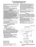
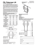
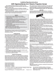
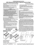
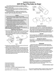
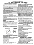
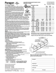
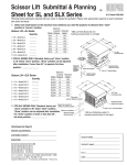
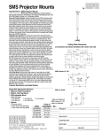
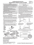
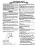
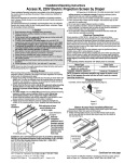
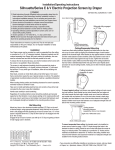
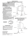
Installation/Operating Instructions
220 V Revelation Video Projector Mount by Draper
These Installation/Operating Instructions are available in the official language
of the country where you purchase the product. Please contact your
distributor to request a copy.
Vous pourriez demander les instructions d’installation et d’opération traduises
dans la langue officielle du pays ou vous achetez le produit. Veuillez
demander à votre distributeur.
Die Gebrauchsanweisung für Installation und Konstruktion sind in der
offiziellen Sprache des Landes, indem Sie das Produkt gekauft haben,
vorhanden. Fragen Sie die jeweilige Verkaufs-Abteilung.
Caution
➀ Read instructions completely before proceeding.
➁ Follow instructions carefully. Installation contrary to instructions
invalidates warranty.
➂ Take great care when handling both first surface mirrors. They will
usually come covered with a protective film. Remove this film after
installation and prior to projecting images. If cleaning is necessary, do
so very lightly with glass cleaner and a soft, lint free cloth.
➃ Do not obstruct operation of door with fingers or any object. Serious
injury or damage could result.
➄ The Revelation is not designed to act as a structural support of ceiling
framing. However, the trim frame is designed to support ceiling T-grid,
tiles and drywall. Equipment should not be allowed to rest on door
at any time.
➅ Entire bottom of unit must be unobstructed to permit proper operation.
Sufficient clearance (432mm minimum) must be allowed below door.
➆ A minimum clearance of 458mm is required above ceiling level for
model B or 347mm for Model A, if plenum housing is used. If no plenum,
the minimum clearance is 331mm for both models.
➇ Unit must be installed level (use a carpenter’s level).
➈ Unit operates on 220 V a.c. 60 hz. current.
Note: Unit has been thoroughly inspected and tested at factory and found
to be operating properly prior to shipment.
Where to install the Revelation
To determine where to mount the Revelation, you need to know the following:
➀ The projector manufacturer’s recommended throw distance (TD). Typically,
a minimum and maximum range is provided per screen size. Select a
throw distance that is 6" greater than the minimum and 6" less than the
maximum stated. We recommend the average of the two numbers. For
example, if the range given is 228" max. and 142½" min., then use a
number between 222" and 148½". We recommend using the average of
185¼" as the TD.
➁ The distance from the center line of the lens to the bottom of the projector’s
feet (CL). To find the mounting point (m = back edge of the rough cut) use
the following formula:
y = 15" + CL
z = TD – y
m = z + 8"
Remember:
CL = Distance from center line of lens to bottom of projectors feet.
TD = Manufacturer’s horizontal throw distance for the selected screen size.
m = Calculated mounting point (mounting point is back edge of rough cut as
measured from screen surface.)
As an example, if you are using a projector with recommended throw distance
(TD) of 185¼" for a 100" diagonal image, and its CL dimension is 4", calculate
the mounting point as follows:
y = 15" + CL
z = TD – y
m = z + 8"
y = 15" + 4"
z = 185¼" – 19"
m = 166¼" + 8"
y = 19"
z = 166¼"
m = 174¼"
In the example above, the distance from the screen to the back edge of the
rough cut would be 174¼". (Formula has a ± 6" accuracy).
y
m
As Soon As Revelation Arrives
z
= CL
➀ Open carton and inspect for damage.
➁ Locate the following parts:
A. The unit itself
B. Controls
Planning
➀ Based on screen location and projector specifications, determine proper
position for projector installation. (First see "Choose a projector based
on its light path" on page 3. Then read "Where to install the
Revelation" below.)
➁ Confirm that there is at least 458mm available above the ceiling for Model
B or 347mm for Model A, if plenum housing is used. If no plenum, the
minimum clearance is 331mm for both models.
➂ Arrange to provide service access to electrical control box and plenum
housing.
➃ If connecting duct work to the plenum housing, plan for position and length
of duct work. (See guidelines under "Installing the Plenum Kit" on
page 6.)
Metric Conversion
1 inch = 25.4 mm
1 inch = 2.54 cm
Copyright © 2007 Draper Inc. Form Revelation220V_Inst07
Printed in U.S.A.
Formula to find m
(mounting point is back edge of rough cut
farthest away from projection screen).
y = 15" + CL
where:
z = TD – y
m = z + 8"
CL = centerline of lens to bottom feet
TD = throw distance
Accuracy: ± 6"
Hanging Unit
The Revelation may be installed in a variety of ways. Typically, it is recessed
above the ceiling and supported by six (6) 3/8" threaded mounting rods. The
bottom of the main pan should be recessed approximately 76mm above
the finished ceiling. The threaded rods should pass through mounting holes
supplied in each corner and secured by nuts above and below. The unit
should then be guy wired or blocked to prevent swinging.
All installations should observe the following guidelines:
➀ Installer must ensure that all fasteners and supports are of adequate
strength to securely support Revelation and projector.
➁ Fastening methods must be suitable for mounting surface, and securely
anchored so that vibration or abusive pulling on unit will not weaken
installation.
➂ Unit should be level, with weight shared more or less equally by all six
threaded mounting rods.
Continued on page 2
220 V Revelation by DRAPER
Page 2 of 8
➃ Bottom of unit must be unobstructed after installation. 432mm minimum
clearance is required below the door.
➄ Access should be provided to electrical control box in case service is
required.
➅ Do not use unit to support adjacent light fixtures, etc.
➆ Do not complete the ceiling below unit until electrical connections have
been completed and unit has been operated successfully.
➇ We recommend that safety cables be attached to the Revelation for
added security (a sound installation practice with overhead equipment).
sary connections and plug the power cord of the projector into the receptacle
provided in the electrical chassis. Power to the Revelation should be turned
off any time electrical connections or mechanical adjustments are made
to the Revelation! Cycle the mirrored door down to the lowered position. You
are now ready to move on to adjusting the image to the screen.
Adjusting Image
First, use your projector’s operating manual to establish proper orientation of
the image and adjust the lens position to achieve the desired image width and
location.
Next, use the Revelation's adjustments to adjust the height of the image on
the screen.
Electrical Connections
Unit operates on 220 V a.c., 60 Hz. current.
Opening the access cover on the electrical control box exposes terminals
for field connections. Unit is shipped with internal wiring complete. Wire for
connecting unit to switch(es) and to power supply should be furnished by
electrician. Connections should be made in accordance with wiring diagram
on page 5, and wiring should comply with national and local electrical codes.
All operating switches should be “off” before power is connected.
Operation
When unit is first operated, be cautious! If door does not begin to open
momentarily when switch is flipped “down”, return switch to “off” and free door
and/or recheck electrical connections before proceeding. Cycle door down
and up several times to confirm satisfactory operation.
Single Station Control (CE Approved)—Moving 3-position switch to “down”
position will start door down. Moving switch to “up” will start door up. When
door is fully down or fully up, it will automatically be stopped by factory set
limit switches. Whenever switch is placed in center “off” position, operation will
stop.
The Revelation has two adjustments:
➀ Always start by sliding the inner pan which holds the projector either backward or forward depending on desired location of image. Sliding the inner
pan towards the projection screen will change where the image strikes the
mirror on the door, and lower the projected image. Inner pan has a travel
range of approximately 8".
➁ Opening the mirrored door even further into the room will lower the
projected image. The limit switch is factory set to let the door open into
the room at a 45° angle. The door can open approximately 10° further by
changing the limit switch’s position.
Adjust the door only if your projector is equipped with keystone correction or a
certain amount of keystoning can be tolerated.
To adjust the limit switch of the door:
TOOLS: screwdriver/Allen wrench (3/16"); electronic level or protractor or other
tool to measure angles.
Multiple Station Control—Each switching station has a three-button switch
with “up”, “down”, and “off” buttons. Door starts up or down when appropriate
button is pressed, and may be stopped by pressing “off” button. Factory set
limit switches stop door automatically when door is fully up or fully down.
Turn the unit on and open the door to its factory set position. Record the angle
measurement.
Key Operated Switch—If ordered, a single station, key-operated three position (up/off/down) switch is available for this unit.
Locate the two limit switch brackets at the edge of the top mirror on the motor
side of the pan. The top bracket controls the downward travel limit of the door
and adjustments are made to this bracket. Note and mark current location of
limit switch bracket. The bottom limit switch bracket is set at the factory for
proper closure alignment and should not need adjusting.
Video Interface Control (VIC12, VIC12 Modified)—This optional control
device allows the Revelation switch to control the operation of a Draper
motorized projection screen via relay.
Infrared or Radio Frequency Remote Control (CE Approved)—A three-button transmitter is provided, with “up”, “down”, and “stop” buttons. Door starts
up or down when appropriate button is pressed, and may be stopped by
pressing “off” button. Factory set limit switches stop door automatically when
door is fully up or fully down.
Installing Projector
The Revelation has a grounded 220 V a.c., 60Hz outlet for projector power
supply. Power is supplied to this outlet at all times.
Holes are provided for power and control wiring.
Install a projector with the capability to invert its image.
Place the projector into the sliding inner pan so that the center of the projector
lens is aligned L to R with the center of the upper mirror. Position the projector
lens as close as possible to the upper mirror without the reflected light path
striking any part of the projector. An extension plate is provided if the feet
of your projector rest inside the opening of the inner pan. The extension
is designed to support the front legs of your projector and the folded up edge
can be used as a stop to help reposition the projector when removed. Adhere
the extension plate only after you have adjusted the image and marked the
position of the plate.
Establish exact placement through trial and error using the various adjustments integrated throughout the design of the Revelation. The upper mirror
can be moved up one inch to accommodate taller projectors. Make the neceswww.draperinc.com
Caution: Any adjustments to the limit switches should be done with the
power to the Revelation turned off!
Use a 3/16" Allen wrench to loosen the two screws on the limit switch bracket
and slide the bracket toward the electrical chassis. A slight adjustment to the
limit switch bracket will result in a significant movement of the door. It is recommended that the limit switch be adjusted in small incremental moves of 1/8".
Tighten the screws. Keeping hands and tools clear of the limit switch, connect
the power. The door should open further. Record the new angle and check the
position of the image on the screen.
If the position of the image on the screen is satisfactory, close the door and
make sure the screws are completely tight.
If the position of the image needs adjusting, leave the door open, disconnect
the power, loosen the screws and slide the bracket toward the motor to open
the door more, or slide the bracket closer to its original position.
Check alignment of image and repeat adjustment procedure as necessary. After all adjustments are completed, be sure to tighten all loosened
screws to inner pan and limit switch bracket!
Securing Projector
Once all adjustments to the projector and Revelation are made, the projector
Please Note
If Glass Shield is provided, see separate instructions (provided
with Glass Shield).
(765) 987-7999
220 V Revelationby DRAPER
Page 3 of 8
should be secured into place using the eight projector standoffs provided. Two
of the standoffs have a removable hook and loop material to be used at the
rear of the projector for ease of removing the projector. The standoffs will ensure proper relocation of the projector after periodic maintenance or repair to
the projector. Just peel the adhesive backing from the bottom of the standoffs
and place them around the projector as shown in the dimensional diagram.
Important: Once the adhesive is placed onto the surface of the inner pan it is
very difficult to remove. It is very important to plan ahead when placing these
standoffs around the projector.
Choose a projector* based on its light path
A
A light path is the projector’s spread of light and its relationship to the centerline of the lens. Since the Revelation folds a light path twice (bounces the
image off of two first surface mirrors), it’s critical to understand your projector’s
light path to know approximately where the image will land on the wall. Consult the projector's manufacturer to determine its light path geometry.
Single lens projectors fall into one of four categories of light path geometry as
depicted in the illustrations at right.
Light Path A
Single lens projectors with light path geometry “A” work well with the Revelation. Since the light is already projecting at a downward angle to the centerline, the image is projected further down on the wall resulting in a lower
installation point for the projection screen. A projector with Light Path A
mounted in the Revelation projects a light path similar to the same projector
ceiling mounted with the centerline of its lens mounted approximately 5176mm (2"-3") below the ceiling.
B
Light Path B
Single lens projectors with light path geometry “B” will work with the Revelation within certain limitations. The upper edge of the image runs parallel
to the centerline of the lens. A projector with Light Path B mounted in the
Revelation projects a light path similar to the same projector ceiling mounted
with the centerline of its lens mounted approximately 153-203mm (6"-8")
below the ceiling. By using the built in adjustment features of the Revelation,
you should be able to bring the top of the image below the ceiling. Adjusting
the ceiling closure door may introduce a keystone effect to the image. If your
projector has a keystone correction feature you may be able to compensate
for keystoning.
C
Light Path C
Single lens projectors with light path geometry “C” will work with the Revelation within certain limitations. The portion of the image above the centerline
of the lens projects at a gradual angle up towards the ceiling. A projector
with Light Path C mounted in the Revelation projects a light path similar to
the same projector ceiling mounted with the centerline of its lens mounted
approximately 153-203mm (6"-8") below the ceiling. By using the built in
adjustment features of the Revelation, you should be able to bring the top of
the image below the ceiling. Adjusting the ceiling closure door may introduce
a keystone affect to the image. If your projector has a keystone correction
feature you may be able to compensate for keystoning.
Light Path D
Single lens projectors with light path geometry “D” will not work with the Revelation. The portion of the image above the centerline of the lens projects at
too steep of an angle to be lowered below ceiling level, even with the adjustment features built into the Revelation.
D
*Consult your projector manufacturer if in doubt about its light path geometry,
throw distance or projector dimensions. Also, be sure your projector has the
ability to invert its image.
www.draperinc.com
(765) 987-7999
220 V Revelation by DRAPER
Page 4 of 8
Revelation Dimensions
6 Mounting
holes 9.525mm (3/8") dia.
TB1
Electrical
hook-up
252
mm
972
mm
603
mm
17mm
394mm
946
mm
462mm
Lens and mirror
centerline
*4
17mm
578mm
*1
8 Projector
standoffs
Projector
165
mm
*2
*2
4"
51mm
248
mm
*3
*1
*2
*3
*4
Model A Model B
232mm 475mm
330mm 457mm
864mm 1118mm
546mm 630mm
Minimum rough opening
597mm x 597mm
Minimum clearance
(Includes allowance for
housing in plenum)
Models A & B-346mm
5mm
17mm
603mm
m=Back edge of rough
cut to screen surface
Revelation Dimensions & Data
Electrical Specifications
Model B
Overall Unit Size (HWL)
330 x 972 x 864mm
330 x 972 x 1118mm
Required Space Above Ceiling*
346 x 972 x 864mm
458 x 972 x 1118mm
Clearance Below Ceiling
approx. 432mm
approx. 432mm
Rough Ceiling Opening
597 x 597mm
597 x 597mm
Capacity
45 kg
45 kg
Door’s Downward Travel Distance
approx. 432mm
approx. 432mm
Travel Time
9 sec.
9 sec.
Net Weight
39 kg
41 kg
Shipping Weight
98 kg
100 kg
Projector Space (HWL)—To fit within parameters of inner pan.
* 346mm is overall height of Revelation with plenum housing (330mm WITHOUT plenum).
www.draperinc.com
Minimum clearance
without Plenum
330mm
76mm
Ceiling line
103
mm
m
Model A
25
mm
65
mm
Operating Voltage
220 V a.c. 50–60 Hz
Amperes
1 Amp**
Control Voltage
12 V a.c.
Motor Specifications:
Voltage
220 V a.c. 50–60 Hz
Amps
.43
Torque
40 IN–lbs.
* Includes allowance for housing in plenum.
** Does not include any load placed on internal outlet.
U.S. patent number 6,379,012
(765) 987-7999
220 V Revelation by DRAPER
Page 5 of 8
Wiring Diagrams for Revelation without Plenum
Single Station Control
COMPONENT SPECIFICATION
SYM.
BE
1
YL
3
5
6
BK
BK
2
RD
4
7
PRIMARY SIDE
YL
8
SECONDARY SIDE
T1 WIRING
WALL SWITCH
SPDT CENTER OFF
Capacitor 2mfd +/- 370 Vac
C2
Capacitor 100mfd 35 Vac
CR1
Relay 12Vac 2PDT 230 Vac 10A
CR2
Relay 12Vac 2PDT 230 Vac 10A
D1
Diode NTE125002B
F1
Fuse 7 Amp AGC 250 Vac
F2
Fuse 1 Amp AGC 250 Vac
F3
Fuse 1 Amp AGC 250 Vac
T1
Transform 230V/12V@1Amp 50/60Hz
MOTOR 220V .03hp 50hz. 200Lb-in. 1.1rpm
TB 1
UP
BK
BE
BK
2
RD
C2
3
BE
YW
BE
CR 1
YW/GN
BE
UP
4
D1
TB 2
BE
SEE T1 WIRING DIAGRAM
10
BK
7
8
N
L1
WH
BE
YW/GN
BK
RD
RD
10 11 12
GND
RD
BE
DOWN
T1
9
220 VAC SUPPLY
50 - 60 HZ
RD
CR 2
YW
BE
RD
C1
YW
BE
RD
BE
14 AWG
F3
RD
BE
RD
14 AWG
1 2 3 4 5 6 7 8 9 10
BK
14 AWG
PCB 1
F2
F1
CB1B
RD
WH
RD
RD
BE
BE
MOTOR
DOWN LIMIT SW
UP LIMIT SW
1
BE
BE
BE
WH
BE
1
RD
RD
YW/GN
PROJECTOR OUTLET
BK
BE
10 9 8 7 6 5 4 3 2
RD
YW
BK
2
BE
WIRING DONE BY INSTALLER
YW/GN
9
RD
BE
8
BE
7
6
RD
RD
6
5
BK
5
BK
4
BE
RD
1
DOWN
3
COM
C1
WH
RD 14 AWG
CB1A
ALL WIRES 18 AWG. UNLESS OTHERWISE SPECIFIED.
Low Voltage Multiple Station and Remote Control
COMPONENT SPECIFICATION
SYM.
BE
1
YL
3
5
BK
BK
2
RD
Red
Brown
Yellow
Green
White
Black
4
7
PRIMARY SIDE
YL
8
SECONDARY SIDE
BE
YW
Diode NTE125002B
F1
Fuse 7 Amp AGC 250 Vac
F2
Fuse 1 Amp AGC 250 Vac
F3
Fuse 1 Amp AGC 250 Vac
T1
Transform 230V/12V@1Amp 50/60Hz
BE
CR 1
YW/GN
BE
UP
D1
4
TB 2
BE
BK
10 11 12
L1
BE
WH
BK
RD
RD
YW
BE
RD
C1
YW
BE
RD
BE
BE
14 AWG
Dashed wiring by Electrician
Low voltage wiring by others
YW
RD
PROJECTOR OUTLET
14 AWG
BE
14 AWG
RD
RD
1 2 3 4 5 6 7 8 9 10
RD
BK
YW/GN
BK
BE
F3
1
14 AWG
PCB 1
F2
F1
CB1B
www.draperinc.com
10 9 8 7 6 5 4 3 2
RD
CB1A
BE
BE
BE
WH
WH
BE
RD
ALL WIRES 18 AWG. UNLESS OTHERWISE SPECIFIED.
(765) 987-7999
9
9
N
BE
RD
BK
8
8
GND
DOWN
T1
BE
YW/GN
RD
CR 2
RD
7
BE
WH
6
7
BN
YW/GN
RD
5
BK
RD
4
6
RD
BE
3
BE
RD
10
RD
BE
2
5
BK
Relay 12Vac 2PDT 230 Vac 10A
D1
BK
C2
SEE T1 WIRING DIAGRAM
WH
Relay 12Vac 2PDT 230 Vac 10A
CR2
BK
BE
3
GN
Capacitor 100mfd 35 Vac
CR1
RD
2
YL
Capacitor 2mfd +/- 370 Vac
C2
BE
1
BN
C1
MOTOR 220V .03hp 50hz. 200Lb-in. 1.1rpm
TB 1
RD
1
Aux Port for connecting additional LVC-III
modules (up to six total-connect from Aux to Eye).
3 Button Wall Switch
DOWN - Black
COM - White
UP - Red
Eye Port for IR Eye, RF Receiver or LED
Switch. If more than one of these three is
used with one LVC-III, a splitter is required.
T1 WIRING
VIDEO INTERFACE OR
CONTROL
220 VAC SUPPLY
50 - 60 HZ
6
BK
MOTOR
DOWN LIMIT SW
UP LIMIT SW
12 V
220 V Revelation by DRAPER
Page 6 of 8
Field Installation of Plenum Kit
FIGURE #1
TB1
7
FIGURE #2
Inner end panel
Inner Plenum cover
Outer Plenum cover
Input
fan
assembly
Exhaust
fan
assembly
Motor
Outer end panel
1
F2
F1
10 9 8 7 6 5 4 3 2
PCB 1
BE
BE
BE
BK
CB1A
8
9
10 11 12
4 TURNS
14 AWG
1 2
RD
I
t
I
I
BE
14 AWG
4 5
CS 1
14 AWG
YW/GN
14 AWG
3
NOTES:
WIRE TO BE REMOVED BEFORE INSTALLING PLENUM WIRING
1.
WIRES CONNECTED BY INSTALLER
2.
3. ALL WIRES 18 AWG. UNLESS OTHERWISE SPECIFIED.
www.draperinc.com
12
Nylon tape 39" long
RD
RD
PROJECTOR
OUTLET
BK
10
6
L1
WH
PCB1
Exhaust
fan
assembly
(long
wires)
BE
BE
F2
F1
Projector
YW/GN
220 VAC SUPPLY N
50 - 60 HZ
PCB1
Curent sensor
F1 = 7 Ampere
F2 = 1 Ampere
F3 = 1 Ampere
F4 = 4 Ampere
F5 = 4 Ampere
BE
BK
C1
CB1A
5
CB1B
RD
FAN
(OUT)
TB2
CR2
1
4
FAN
(IN)
CR1
F3
10
3
BK
BK
1 2 3 4 5 6 7 8 9 10
2
BK
CS1
CB1B
1
BK
WH
1
12
BK
F3
D1
BK
BK RD
12 345
Input
fan
assembly
(short
wires)
TB 1
BK
F4
F5
T1
Wire clips typ.
DIAGRAM #1
C2
T2 transformer
T2
TB1
1
Nylon tape 43" long
1
Caution! Disconnect power from the Revelation before installing plenum.
➀ Remove the covers from the electrical chassis in the Revelation.
➁ Disconnect the black 14 awg. wire that runs from the T2 transformer to
the receptacle in the electrical chassis.
➂ Install the pre-wired current sensor using two #6-32 x 1" [10] long screws
provided. (SEE FIGURE #1.)
➃ Connect each wire of the pre-wired current sensor as shown by DIAGRAM #1.
➄ Install the two fan mount assemblies [5,6] to the main pan of the Revelation using the eight #10-32 x .3/8" [7,8] long screws provided. (SEE
FIGURE #1.) Attach the long leads of the Exhaust Fan Assembly [6] to
the end with the motor and lifting mechanism.
➅ Using the wire clips [11] provided, lay in the wires from the fans as
shown in FIGURE #1 and connect the fans to TB1-8 & TB1-9 as shown
in DIAGRAM #1.
➆ Replace the covers to the electrical chassis.
➇ Apply the 25 mm wide Nylon [12,13] tape as shown in FIGURE #1.
➈ Install the inner and outer plenum covers [1,2], and attach the mating
end panel [3,4] as shown in FIGURE #2.
➉ Fan mounting panels are designed to accept a standard 4" round duct.
The exhaust flange is located on the motor/drive end of the Revelation
and the input is located at projector end of the Revelation.
If duct work is connected to this unit, here are a few recommended guidelines
you should keep in mind when installing the duct work:
• Air supply to the plenum should be cool enough to provide adequate cooling for your projector.
• Do not obstruct airflow through duct work. Inadequate airflow may result in
excessive heat buildup inside the unit.
• Keep duct work length as short as possible. Recommended maximum total
duct length is 914 cm (input plus exhaust).
• Keep the input-to-exhaust length ratio balanced and as small as possible
to prevent air from being pushed into or drawn out of the room.
(765) 987-7999
PLENUM INSTALLATION PART LIST
ITEM#
DESCRIPTION
QTY
1 INNER PLENUM COVER
1
2 OUTER PLENUM COVER
1
3 INNER END PANEL
1
4 OUTER END PANEL
1
5 INPUT FAN MOUNT ASSEMBLY
1
6 EXHAUST FAN MOUNT ASSEMBLY
1
7 SCREW #10–32 X .375" (9.525mm)
8
HEX HD TYPE "F" ZINC
8 WASHER, #10 ZINC INTERNAL LOCK
8
9 PRE-WIRED CURRENT SENSOR
1
10 SCREW #6–32 X 1" (25.4mm)
2
LONG PHIL PAN HD ZINC
11 CLIP ADHESIVE BACKED CORD
7
6.35mm HOLDING DIA.
12 991 mm LONG 25.4mm WIDE X .762mm
1
THICK NYLON TAPE
13 1092mm LONG 25.4mm WIDE X .762mm
1
THICK NYLON TAPE
TOOLS NEEDED
MED POINT PHILLIP SCREWDRIVER
1
/8" FLAT BLADE SCREW DRIVER
3
/8" WRENCH
220 V Revelation by DRAPER
Page 7 of 8
Plenum Operating Instructions
The Revelation plenum features a unique design that allows easy access to
virtually anywhere inside the unit. Access is achieved by removing either end
panel. End panels feature captive screw assemblies so no hardware can be
lost or misplaced. Once the end panel is removed, slide the plenum housing
toward the center of the unit. Service and maintenance is made simpler due to
the accessibility provided by this unique plenum design.
Each plenum also features a ventilation system designed to maintain a suitable operating environment for your projector. An integrated current sensor
in the Revelation circuitry turns on the fans anytime the projector is operating
and circulates fresh air through the unit. Two 4" duct flanges are located on
the ends of the plenum for installation of duct work for directing the airflow to
and from the unit. The input flange is located on the motor/drive end of the
Revelation and the exhaust is located at projector end of the revelation. If duct
work is attached to the Revelation, follow guidelines in Plenum Installation
Instructions on page 6.
Wiring Diagrams for Revelation with Plenum
Single Station Control
BE
1
YL
3
5
6
BK
2
BK
RD
4
7
PRIMARY SIDE
SECONDARY SIDE
T1 WIRING
WALL SWITCH
SPDT CENTER OFF
TB 1
UP
BK
C2
3
BE
YW
CR 1
Fuse 1Amp AGC 250 Vac
FAN
220Vac 8Watt 50cfm 1600rpm
T1
Transform 220V/12V@1Amp 50/60Hz
TB 2
RD
8
9
BE
BE
WH
BK
RD
10 11 12
RD
YW
BE
RD
C1
YW
BE
RD
BE
RD
BE
RD
1
10 9 8 7 6 5 4 3 2
RD
BK
BE
F3
1 2 3 4 5 6 7 8 9 10
YW/GN
14 AWG
PROJECTOR OUTLET
PCB 1
F2
F1
CB1B
14 AWG
BE
4 TURNS
14 AWG
BK
1 2
WH
RD
RD
BE
BE
MOTOR
DOWN LIMIT SW
UP LIMIT SW
1
YW
RD
BK
BK
RD 14 AWG
RD
2
BE
14 AWG
WIRING DONE BY INSTALLER
BK
DOWN
T1
BE
RD
CR 2
9
7
BE
RD
YW/GN
8
RD
7
BE
10
RD
6
6
BE
BE
BE
WH
BE
BE
WH
RD
CB1A
RD
3
4 5
CS 1
I
I
t
I
ALL WIRES 18 AWG. UNLESS OTHERWISE SPECIFIED.
Low Voltage Multiple Station and Remote Control
BE
1
YL
3
5
6
BK
2
BK
RD
4
7
PRIMARY SIDE
RD
8
YL
SECONDARY SIDE
T1 WIRING
BN
YL
TB 1
1
BE
YW
5
10
BE
WH
RD
RD
YW
RD
C1
YW
BE
RD
BE
L1
BE
14 AWG
Dashed wiring by electrician
YW
Low voltage wiring by others
RD
RD
BE
RD
1
PCB 1
F2
F1
CB1B
14 AWG
BK
BE
4 TURNS
14 AWG
1 2
10 9 8 7 6 5 4 3 2
YW/GN
14 AWG
PROJECTOR OUTLET
BK
BE
F3
1 2 3 4 5 6 7 8 9 10
RD
BK
BK
RD 14 AWG
RD
CB1A
3
4 5
ALL WIRES 18 AWG. UNLESS OTHERWISE SPECIFIED.
I
t
I
I
www.draperinc.com
BE
BE
BE
WH
BE
BE
RD
CS 1
9
BE
BE
BK
RD
WH
RD
RD
BE
BE
BE
BK
DOWN
BK
(765) 987-7999
WH
YW/GN
8
RD
7
RD
CR 2
T1
BE
10 11 12
N
Transform 220V/12V@1Amp 50/60Hz
6
BE
9
GND
220Vac 8Watt 50cfm 1600rpm
T1
5
RD
YW/GN
220 VAC SUPPLY
50 - 60 HZ
Fuse 1Amp AGC 250 Vac
FAN
TB 2
RD
BE
RD
8
BK
Fuse 1Amp AGC 250 Vac
F3
4
RD
7
FAN
(OUT)
Fuse 7Amp AGC 250 Vac
F2
BK
6
FAN
(IN)
Diode NTE125002B
F1
YW/GN
BE
BE
SEE T1 WIRING DIAGRAM
BK
BK
Current sensor 230Vac 2-20Amp SASC
D1
BE
CR 1
UP
D1
4
VIDEO INTERFACE
CONTROL
OR
Relay, Coil-12Vac, 2PDT 230Vac 10Amp
CS1
BK
C2
3
BN
Relay, Coil-12Vac, 2PDT 230Vac 10Amp
CR2
RD
2
Aux Port for connecting additional LVC-III
modules (up to six total-connect from Aux to Eye)
CR1
BK
BE
WH
BK
Capacitor 100mfd 35 Vac
MOTOR 220V .03hp 50-60hz. 200Lb-in. 1.1rpm
GN
3 Button Wall Switch
DOWN - Black
COM - White
UP - Red
Capacitor 2mfd +/- 370 Vac
C2
3
Eye Port for IR Eye, RF Receiver or LED
Switch. If more than one of these three is
used with one LVC-III, a splitter is required.
COMPONENT SPECIFICATIONS
C1
2
Red
Brown
Yellow
Green
White
Black
SYM
1
L1
Fuse 1Amp AGC 250 Vac
F3
YW/GN
BE
BE
YW/GN
N
F2
MOTOR 220V .03hp 50-60hz. 200Lb-in. 1.1rpm
SEE T1 WIRING DIAGRAM
RD
BK
220 VAC SUPPLY
50 - 60 HZ
Fuse 7Amp AGC 250 Vac
BK
FAN
(OUT)
GND
F1
BK
5
FAN
(IN)
Current sensor 230Vac 2-20Amp SASC
Diode NTE125002B
BE
UP
D1
4
BK
Relay, Coil-12Vac, 2PDT 230Vac 10Amp
D1
5
BK
Relay, Coil-12Vac, 2PDT 230Vac 10Amp
CS1
RD
2
RD
Capacitor 100mfd 35 Vac
CR1
4
DOWN
BK
BE
1
BE
Capacitor 2mfd +/- 370 Vac
C2
3
COM
COMPONENT SPECIFICATIONS
C1
CR2
YL
8
SYM
MOTOR
DOWN LIMIT SW
UP LIMIT SW
12 V
220 V Revelation by DRAPER
Page 8 of 8
VIC12 Kit Installation Instructions
➀
Close the door to the Revelation.
➁
DISCONNECT POWER TO THE REVELATION.
➂
Remove the covers from the electrical enclosure.
➃
Attach the pre-wired limit switch [1] to the shaft mounting bracket which
is closest to the motor as shown in FIGURE #1. Using the
#6–32 x 1" [2] long screws and #6 lock washers [2] provided.
➄
Run the wires through the open grommet in the end of the electrical
enclosure that is toward the motor as shown in FIGURE #1 and connect
them as follows:
FIGURE #1
CR 1
TB 2
1 2 3 4 5 6 7 8 9 10
The VIC 12 KIT includes all the components necessary for the VIC 12 to work
with the Revelation. Follow these steps to install the components in this KIT.
CR 2
C1
Motor
Blue
Black
Pre-wired limit switch
Connect the black wire to screw #1 of TB2
Connect the blue wire to screw #2 of TB2. (Be sure that wires do not
interfere with moving linkage or the sliding inner pan)
➅
Put the 12V ACTIVATOR LEVER [3] onto the shaft as shown in Figure
#2. The 12V ACTUATOR LEVER will need to be spread out before it will
fit onto the shaft. The door to the Revelation must be closed before going
on to step #7
➆
Position the 12V ACTUATOR LEVER by rotating it into the limit switch
until the limit switch clicks and secure the lever onto the shaft using the
#10-32 screw [4] and lock washer [5] supplied with the lever. (Be sure
that the screw on the lever is tightened so that the lever does not twist on
the shaft.)
➇
After the VIC 12 [7] is installed with the screen, run the wiring to the
Revelation using the cord strain relief [6] and connect to TB1 as shown
in the Revelation wiring diagram.
➈
Put the covers back on to the electrical enclosure.
➉
Reconnect power to the revelation.
FIGURE #2
12V actuator lever
Rotate lever
until the limit
switch clicks.
Tighten lever
onto shaft.
Pre-wired
limit switch
VIC 12 OR VIC 12 MODIFIED INSTALLATION PART LIST
ITEM #
DESCRIPTION
QTY
1
PRE-WIRED LIMIT SWITCH
1
2
SCREW #6–32 X 1"(25.4mm) LONG
PHIL PAN HD W/ EXT LOCK WASHER
2
3
12v ACTUATOR LEVER
1
4
SCREW #10–32 X 3/8" (9.525mm) LONG SHCS
1
5
WASHER #10–.190" I.D. X .375" (9.525mm) O.D.
ZINC INTERNAL TOOTH
1
6
FITTING CORD CRIMP STRAIN RELIEF
1
7
VIC 12 OR VIC 12 MODIFIED
1
TOOLS NEEDED
MED POINT PHILLIP SCREW DRIVER
I
/8" FLAT BLADE SCREW DRIVER
3
/16" ALLEN WRENCH
www.draperinc.com
(765) 987-7999
12V Actuator lever