1
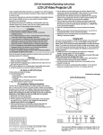
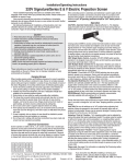
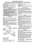
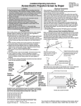
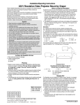
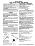
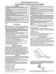
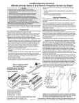
Installation/Operating Instructions
220V Targa Electric Projection Screen by Draper
These Installation/Operating Instructions are available in the official language of the
country where you purchase the product. Please contact your distributor to request a
copy.
Vous pourriez demander les instructions d’installation et d’opération traduises dans
la langue officielle du pays ou vous achetez le produit. Veuillez demander à votre
distributeur.
Die Gebrauchsanweisung für Installation und Konstruktion sind in der offiziellen
Sprache des Landes, indem Sie das Produkt gekauft haben, vorhanden. Fragen Sie die
jeweilige Verkaufs-Abteilung.
Caution
① Read instructions through completely before proceeding.
② Follow instructions carefully. Installation contrary to instructions invalidates
warranty.
③ Screen should be accessible for complete removal should fabric become
damaged or should other service be required.
④ Screen should be installed level (using a carpenter’s level).
⑤ Nothing should be fastened to screen dowel or viewing surface.
⑥ Operating switch(es) packed separately in screen carton. Do not discard with
packing material.
⑦ Screen operates on 220V AC, 50 Hz., 1 ph. current.
NOTE: Screen has been thoroughly inspected and tested at factory and found to be
operating properly prior to shipment.
Hanging Screen
General: When locating viewing surface and checking clearance for screen’s operation,
remember surface is centered in case. Handle case carefully to protect its finish.
Regardless of mounting method, screen should be positively and securely supported
so that vibration or even abusive pulling on the viewing surface will not cause case to
work loose or fall. Installer must insure that fasteners used are of adequate strength and
suitable for the mounting surface chosen.
Suspended Installation:
Suspend screens from holes in endcaps as shown. S-hooks, chains (or cable) and
turnbuckles should be provided by installer. “S” hooks should go through the front holes
on the endcaps (see drawing on page 2), and both ends of the “S” hooks should be
crimped for additional safety. Chains should be attached to beams or other structural
members. Turnbuckles should be adjusted so screen hangs level.
Wall Installation:
Mount screen through holes in back of endcaps as shown. Installer should furnish
screws, toggle bolts, molly bolts, nylon or lead anchors as required.
Wall Installation with 15 cm Extension Brackets:
Mount the brackets (not included with screen—see diagram below right) using hardware
recommended for “Wall Installation” (above). Then, suspend the screen from the front
holes with “S” hooks (as in “Suspended”). For added safety, crimp both ends of the “S”
hooks so the screen cannot come off. For a more rigid installation, mount the screen
from the back holes to the front of the bracket by using the screws and nuts provided
with the brackets.
Recessed Installation:
Recess should permit access for removal of screen if necessary. Screen may be
mounted as in suspended or wall installation. Optional Ceiling Opening Trim Kit available; see diagrams below and on page 2, and separate instruction sheet (included with
Ceiling Opening Trim Kit).
15 cm Extension
Bracket
Screen Case
15
cm
Back
Ceiling Tile
(By others)
Electrical Connections
Screen operates on 220V AC, 50 Hz., 1 ph. current.
Junction box is located inside left endcap and cover plate is secured to endcap with two
screws. Junction box contains brown, black and blue pigtail leads and green internal
ground wire, per wiring diagram on reverse.
Screen is shipped with internal wiring complete and control switch (es) fully boxed. Wire
connecting screen to switch (es) and switch (es) to power supply should be furnished by
installer. Connections should be made in accordance with wiring diagram supplied, and
wiring should comply with national and local electrical codes.
All operating switches should be “Off” before power is connected.
®
Copyright © 2010 Draper Inc.
Form Targa220V_Inst10-R
Printed in U.S.A.
Operation
Before operating screen remove tape securing fabric and dowel to roller. If viewing
surface hangs out of case 22 or 23 mm, tape has probably been broken by rough
handling in shipment, allowing surface to “unwrap” one turn about the roller. Manually
wrap fabric back around roller without turning the roller itself.
Note: Drive unit contains a thermal overload protector. Operation as frequently as six
cycles per hour may trip the protector. If tripped, the protector should reset automatically
within a few minutes.
220V AC Single Station Control—3-position up-off-down switch permits operation to
be stopped at any point. Factory adjusted limit switches automatically stop screen when
fully down or fully up.
220V AC Multiple Station Control (Not CE approved)—Switches are similar in
appearance to 220V Single Station Control. Screen stops when switch is released
and may be restarted in either direction. Factory adjusted limit switches stop screen
automatically when fully up or fully down.
24V Control—Three-button up-stop-down switch(es) stop at any point desired, operate
in any sequence. Factory adjusted limit switches automatically stop screen when fully
up or fully down. Installer should incorporate an all-pole disconnect in the fixed wiring.
Key Operated Switching (Not CE approved)—Two kinds of key-operated switches
are optionally available with this unit. ① The key-operated power supply switch controls
power to the screen and switches. When it is “off”, the switches will not operate screen.
Key may be removed from the switch in either “on” or “off” position. ② A three-position
key switch permits the screen to be operated directly by key. In this case, the screen’s
operator must always have a key.
RS232/Ethernet—Serial communication and network communication optionally
available with wall switches, RF or IR remote.
Plug & PlayTM—Provided with handheld IR remote control transmitter and 3m cord.
No wiring necessary except to connect to RS232. Screen is equipped with a handheld
remote or 3-position operating switch (see below). Three positions (up-off-down) permit
operation to be stopped at any point. Factory adjusted limit switches automatically stop
screen when fully down or fully up.
Adjustments
Tools needed: Flashlight, small flathead screwdriver/Allen wrench (4mm or 5/32").
Screen settings have been factory set as ordered and should not normally require
further adjustment. However, if you find it necessary to adjust for more or less viewing
area, proceed as follows.
CAUTION: Always be prepared to shut screen off manually when new
adjustment is being tested. Screen may be severely damaged if viewing surface
is allowed to run too far up or too far down. When running up, the dowel should
never wrap over the roller. When run to the down limit, a minimum of 1¼ wraps of
fabric must remain on the roller.
The motor limit screws are normally located on the audience left of screen roller, and
the viewing surface rolls off the back of the roller. If the viewing surface is coming off
the front of the roller (motor on left), or the motor is on the audience right of the screen
roller (with viewing surface rolling off the back), reverse the below instructions.
"DOWN" LIMIT ADJUSTMENT
To Reduce Screen Drop
① Raise screen surface about 30 cm above desired setting and turn off.
② Turn the DOWN limit screw (I) clockwise (three screw turns = ½ roller revolution).
③ Test by running screen down and repeat steps 1 and 2 until desired position is
reached.
To Increase Screen Drop
① Run screen to the down limit.
② With the down switch on, turn the DOWN limit screw (I) counterclockwise (three
turns of screw equals ½ roller revolution) to increase drop.
③ Test by running screen up about 1' and back down to new down limit.
④ Repeat steps 2 and 3 until desired position is reached.
CAUTION: At least 1¼ wraps of fabric must remain on the roller when screen is
at the down limit!
"UP" LIMIT ADJUSTMENT
Screen is Running Too Far Up
① Lower screen surface about 30 cm below desired setting and turn off.
② Turn the UP limit screw (II) clockwise (three screw turns = ½ roller revolution).
③ Test by running screen up.
④ Repeat steps 1 through 3 until desired position is reached.
Screen Needs to Run Up More
① Run screen down about 1' and turn off.
② With the up switch on, turn the UP limit screw (II) counterclockwise (three turns of
screw equals ½ roller revolution).
③ Repeat steps 1 and 2 until desired position is reached.
CAUTION: Do NOT allow the dowel to wrap up over the roller when the screen
is running up! This could damage the screen.
Limit Adjustments (Built-in Low Voltage Motors)
➀ Connect the ILT switch to the motor via the terminal blocks, or via the modular port
using four conductor modular cable. When using modular cable, the cable connectors MUST NOT be crimped in reverse, as with standard telephone cable.
➁ Set the slide switch to the lower position. Press and hold the DOWN button on the
switch to move the viewing surface to the desired lower limit. If the screen moves in
the opposite direction, release the DOWN button and press and hold down the
STOP button for four seconds. This will reverse the operation of the UP and DOWN
switches.
③ Move slider switch into center position. Wait a couple of seconds.
Please Note: If you move the slider switch from down to up in one motion it sets
the two limits in the same postion. Continued on Page 2
If you encounter any difficulties installing or servicing your Targa screen, call your dealer or
Draper, Inc. Spiceland, Indiana, U.S.A., telephone (765) 987-7999 or fax (765) 987-1689.
Page 2 of 3
Targa 220V Instructions by Draper
Case Dimensions/Installation Diagrams
Wall Mounted
Suspended
Appropriate hardware
provided by installer.
134mm
Fabric width + 192mm
59mm
Appropriate hardware
provided by installer.
150mm
22mm dia.
electrical
connection
hole
Viewing
surface
96mm
Wiring Diagrams—220V Motor and Quiet Motor
Methods of Installation
Please Note: Do not wire motors in parallel.
Fasteners for Crimp
wall mounting both
by others.
ends
S Hooks for
suspended
installation
by others.
Single Station Control
CE Approved
Junction box at
left end of screen
Junction box at
left end of screen
Multiple Station Control
Not CE Approved
Internal Screen Wiring
Blue-220v (Common)
Brown-220v (Down)
Black-220v (Up)
Internal Screen Wiring
Blue-220v (Common)
Brown-220v (Down)
Black-220v (Up)
7/8"
hole for
electrical
connection.
Green/Yellow (Motor Ground)
Green/Yellow (Motor Ground)
Cap off with wire
nut & tape
Blue
Red
Black
Control
switch
Black
Black
Hot
220v,
50 Hz.
Blue
Red
Neutral
Neutral
Dashed wiring
by installer
L1
Optional Ceiling Opening Trim Kit
(Dims-Side View)
Blue
Red
Dashed wiring
by installer
220v, 50 Hz.
203
mm
Wiring Diagrams—220V Motor and Quiet Motor
with Built-in Low Voltage Controller
Single Low Voltage Control
Multiple Low Voltage Controls
67
mm
Internal Screen Wiring
White (Neutral)
Black
Green (Ground)
1.6
mm
54 mm
Internal Screen Wiring
White (Neutral)
Black
Green (Ground)
102 mm
162 mm
ILT Limit Adjustment Continued from Page 1
POTS
➃ Set the slide switch to the higher position. Move the viewing surface to the desired
upper limit by pressing and holding the UP button on the wall switch.
➄ Return the slide switch to the center position to return to normal operation.
➅ To set the viewing surface to an alternate format position, move the viewing surface
to the desired position and press the STOP button.
Press and hold STOP for at
To Motor
with
FUNCTION
POSITION
least three seconds to record
UD
C + Built-In
5V
p o
o
Low Voltage
Set LOWER limit
DOWN
the position.
w
m DC
n
m
o
Please Note: Pressing and
Set UPPER limit
UP
n
releasing the UP button on the
CENTER Normal Operation
P
PO
OT
TS
S
switch will move the screen to its
upper limit. Pressing and releasing the DOWN button
will move the screen to its lower limit.
To Motor
While the motor is in motion, pressing STOP for
with
Slide
less than two seconds will stop the viewing surface Switch
Built-In
Low Voltage
at its present position.
Back View
Once the motor is stopped, pressing the STOP
button will move the viewing surface to its alternate format position.
Pressing and holding the STOP button, when the motor is at rest or in motion, for at
least three seconds will record a new alternate format position.
www.draperinc.com
Dashed wiring
by electrician
Data Cable
Dashed wiring
by electrician
Data
Cables
Wall Switch,
RF or IR
Receiver,
or integrated
control system
To 220V Line
(765) 987-7999
To 220V Line
Wall Switches,
RF or IR
Receivers,
or integrated
control systems
Page 3 of 3
Targa 220V Instructions by Draper
Wiring Diagrams—Plug & Play 220V Motor
with Built-in Low Voltage Controller
Single Low Voltage Control
Multiple Low Voltage Controls
Internal Screen Wiring
Internal Screen Wiring
White (Neutral)
White (Neutral)
Black
Green (Ground)
Black
Green (Ground)
Data Cable
Data
Cables
Wall Switch,
RF or IR
Receiver,
or integrated
control system
220V
Wall Switches,
RF or IR
Receivers,
or integrated
control systems
220V
External Low Voltage and Wireless
Internal Screen Wiring
White/Blue (Common)
Red 110/Black 220 (Up)
Black 110/Brown 220 (Down)
Green/Yellow
(Motor Ground)
White or Blue-Common to screen & 110/220V AC Neutral
Red-to screen (directional)
Brown-to screen (directional)
Yellow-to 110/220V AC-Hot
Black-to 110/220V AC-Hot
Green/Yellow (Ground)
Dashed wiring by electrician
Low voltage wiring by others
Eye Port for IR Eye, RF Receiver or LED
Wall Switch. For more than one of
these, a splitter is required.
3 Button Wall Switch
DOWN - Black
COM - White
UP - Red
Aux Port for connecting additional LVC-III
modules (up to six total can be linkedconnect from Aux to Eye).
To
110/220V
Line
STOP
Location of key
operated on-off
switch if furnished
STOP
Control
Switches
24v DC
Two-Way Serial Communication (RS232) with MC1
Internal Screen Wiring
Program LED
Fuse
White or Blue-Common
Red-to Screen (directional)
Black-to Screen (directional)
Brown-Hot to AC
Green/Yellow-Ground
White/Blue (Common)
Red 110/Black 220 (Up)
Black 110/Brown 220 (Down)
Green 110V/
Green/Yellow 220V
(Motor Ground)
Low Voltage Wiring by others
AC Wiring by electrician
RS232 Data FROM Control System
RS232 Data TO Control System
Signal Ground & Manual Switch Common
Manual Switch Down
Manual Switch Up
MC1
Location of key
operated on-off
Eye Port for IR Eye. For RF Receiver or LED
switch if furnished
Wall Switch, a Splitter and a Power Supply
is required. Plug RF Receiver or LED Wall
Switch and Power Supply into splitter, then
run cable from Splitter to MC1 Eye Port.
To AC Line
www.draperinc.com
(765) 987-7999
See separate Serial CommunicationRS232 Instruction
sheet for enabling
RS232 with the MC1.