1
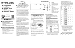
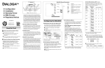
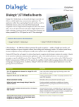
D/41H & D/21H Grounded Static-Dissipative Wrist Strap Ground n Warranty Period n RMA Process n Regulatory Notices 05-0528-002 JP 1 JP5/ 6 S W1 JP 101 JP1 JP5–JP6 JP 201 Grounded Static-Dissippative Mat Read Me First Protect Yourself from Electric Shock To reduce the risk of electric shock: n Switch off the power and remove power cords before opening the PC cover to install the D/41H or D/21H. J3 Figure 1. Static-safe work area n Wear a grounded, static-dissipative wrist-strap for the entire hardware installation. n Keep the board in its anti-static container when it is not being handled. n Work at a static-safe work area (see Figure 1). The default offset address for the D/41H and D/21H is 0000H. If you need to change an offset address, set the switches 1, 2, and 3 on SW1 (see Figure 2) as follows: Offset Address (Hex) SW1:1, 2, 3 Top Edge View off off off 2000* 1 2 3 4 off off on 4000* 1 2 3 4 off on off 6000* 1 2 3 4 off on on 8000 1 2 3 4 on off off Each D/41H, D/21H or compatible voice board installed in a computer must have a unique memory address consisting of a base memory address segment and an offset address. A000 1 2 3 4 on off on Set the Base Memory Address Segment (JP5 and JP6) C000 1 2 3 4 on on off E000 1 2 3 4 on on on JP101– JP401 SW1 0000* (default) — SW1: Switches — 1 2 3 1 2 3 4 A static-safe work area consists of a grounded staticdissipative wrist strap and a work surface covered with or composed of a grounded static-dissipative material. The work surface drains electrical charges from conductive materials when the materials are placed on the surface. The grounded static-dissipative wrist strap drains static charge from the person wearing the strap. Both components ensure that static charges are drained at a rate and current level that are safe. Both must be used any time a person is handling any component. Your application software or Dialogic software release (hereinafter collectively called “voice software”) may have special installation or configuration instructions or requirements. Be sure to read all software documentation for any such instructions or requirements. Installation Order You can install the D/41H or D/21H and voice software in any order, but Dialogic recommends that you install the voice software first when running in a Windows 95 or Windows NT environment, and the board first in any other operating system environment. * J3, J4, JP301, and JP401 are not available on the D/21H board. Configuring the Hardware Installing More Than One Voice Board (JP7) You can install up to 16 D/41H or D/21H boards in a system. One and only one board in a system can have the jumper on JP7 installed (see Figure 2): n One board: Leave the jumper on JP7 installed (default). n Multiple boards: Remove the jumper on JP7 from all but one board. Set the Memory Address The default base memory address segment for the D/41H and D/21H is D000H (Hexadecimal). Generally, you should use the default unless there are more than eight boards in your system or if other non-Dialogic devices in your system must use the D000H segment. Select the base address memory segment with jumpers JP5 and JP6 as follows: 1 2 3 4 Base Address JP6 / JP5 (Hex)* Top Edge View D/41H or D/21H Factory Defaults You may be able to use the factory defaults when installing the D/41H or D/21H board. Read through these instructions and check for possible hardware interrupt level (IRQ) and memory address conflicts between the D/41H or D/21H board and other software or hardware devices (for example, video card or CD ROM controller card) before installing the board. Note: If you own a software utility that can determine what IRQs and memory addresses are in use, run it to help determine potential conflicts before installing the D/41H or D/21H. Some voice software includes such a software utility, or a separate board configuration utility, to help with the D/41H or D/21H installation and configuration. 7 JP 12 Q I R 11 Q I R 10 Q IR 7 Q IR 5 Q IR 4 Q IR 3 Q I R 2/ 9 Q IR Computer boards are static-sensitive and can be damaged by touching or handling them. To prevent damage from static electricity, do the following: J4 JP7 Function RJ-11 jacks for interface with PBX or central office (CO) lines * Jumper block to set interrupt level Jumper pins to set base memory segment Jumper pins to enable hardware interrupt circuitry for multiple boards Jumper pins to set ring detection threshold * Switches to set the offset address and default hook switch state JP401 5 JP 6 JP Protect the Board from Static Electricity JP301 1 :4 SW 1: 3 SW 1: 2 SW 1: 1 SW n Do not re-attach power cords and switch on power to the computer while the PC cover is removed. J1 J2 Common Ground Point Read Your Software Documentation Copyright © 1997 Dialogic Corporation. All Rights Reserved. Part J1–J4 JP7 n Configuration n Installation Set the Offset Address (SW 1: 1, 2, 3) D/41H Physical Description Figure 2. Top edge view of SW1, JP5/6, JP1, and JP7 Set the Hardware Interrupt Level (JP1) The default hardware interrupt level setting (IRQ) is IRQ 9 (a jumper on JP1 pins labeled IRQ 2/9 as shown in Figure 2). Change the IRQ by moving the jumper on JP1 to another IRQ setting if IRQ 9 is already in use. Notes: 1) Set every D/41H, D/21H and compatible board in the system to the same IRQ level. 2) Although the pins for IRQ 9 are labeled IRQ 2/9, IRQ 2 is not available for this board. JP6 JP5 D000 (default) removed removed A000 † removed installed B000 † installed installed C000 ‡ installed removed * Be aware of possible conflicts with devices that often use these segments: † video adapters; ‡ disk controller BIOS. * Base memory address segment B000H does not support offset address settings 0000H – 6000H. n While you can set only one D/41H or D/21H board to an offset, you can set multiple boards to consecutive offsets within a base memory segment as shown in the following example. Board 1 2 3 4 Base:Offset (Hex) D000:0000 D000:2000 D000:4000 C000:A000 Lines 1–4 5–6 7–10 11–14 Board D/41H D/21H D/41H D/41H n Write the IRQ level and memory address settings below for use when installing system software: IRQ Base Offset Lines/Board Setting the Initial Hook Switch State (SW1:4) SW1 switch 4 (SW 1:4 in Figure 2) sets the initial hook switch state for the D/41H and D/21H board. This setting is active only when the PC is powered on but the firmware has not yet been downloaded to the board. If the initial hook switch state is set to on-hook (default) the board presents an inbound call with a ring no answer state. You can change the initial hook switch state to offhook to present a busy signal instead. 4. Insert the board’s edge connector into the bus slot. 5. Replace and tighten the retaining screw. Select a new slot and repeat steps 3–5 for each board you are installing. Replace the PC cover when finished. Make the Connections 2. Call Dialogic Technical Support at 1-973-993-1443 to confirm that it is a problem board. 3. Call the RMA coordinator at 1-973-993-3000 x6374. Telephone lines are open from 9 a.m. to 5:30 p.m. EST. Give the board’s serial number (two letters and six digits—located on a label attached to the board) and a brief description of the problem to the RMA coordinator. The RMA coordinator will give you an RMA number and an estimated return date. It is not necessary to set all D/41H or D/21H boards in the system to the same initial hook switch state. Caller Hears Hook Switch State Ring no answer (default) on-hook Busy off-hook SW1:4 Top Edge View Set SW1:4 off 1 2 3 4 Note: If the PC is not powered on, the inbound call response is ring no answer when a board receives a call. Increasing Ring Detection Threshold Behind a PBX (JP101–JP401) If a board has problems detecting rings behind a PBX, you can lower the ring detection threshold. To lower the threshold on a channel-by-channel basis, install the jumpers (see D/41H Physical Description) as follows: Channel 1 Channel 2 Channel 3 Channel 4 4. While observing correct static-handling procedures, disconnect power, cables, and remove the board from the chassis. on 1 2 3 4 Jumper JP101 Jumper JP201 Jumper JP301 Jumper JP401 Note: A lower threshold may be too sensitive for boards connected to the CO and cause false detection of rings. Installing the Hardware 1. Prepare a static-safe work area, turn off all power to the system, and disconnect the system’s power cords from electrical outlets. See Figure 1. 2. Remove the PC cover. 3. Select an empty ISA expansion bus slot, and remove the slot’s retaining screw and access coverplate. If you suspect you have a problem board, you can return the board to Dialogic for servicing. The following outlines the procedures that make up the Return Material Authorization (RMA) Process. 1. Check to see if the problem is due to a mistake or oversight in the installation process. Be sure to run the diagnostic utility if you have not already done so. Once the firmware is downloaded, the hook switch state is set to on-hook, and may only be changed by the application controlling the board. Figure 3. Bracket showing voice ports n The D/41H and D/21H support a single analog voice channel per RJ-11 jack (channel 1 corresponds to J1, channel 2 corresponds to J2, and so on). Use RJ-11 connectors and phone cable to connect each voice channel jack to a PBX or the CO (see Figure 3). n A standard telephone will not function when directly attached to a D/41H or D/21H RJ-11 jack. After Installing the Hardware n Install the voice board software as described in the documentation provided for the Dialogic software release and operating system in use. n Test the boards using D40CHK.EXE or other diagnostic utilities such as UDD (Universal Dialogic Diagnostics) that came with the Dialogic software release for the D/41H and D/21H. n For specifications and product information, refer to the Dialogic On-Line Information Retrieval System, 1-800-755-5599 or 1-973-993-1063. Warranty Period The D/41H and D/21H boards have lifetime warranties. See the Hardware Limited Warranty card for coverage details. Regulatory Notices RMA Process 5. Repack the board, observing correct static-handling procedures. Place the board in an anti-static container and then put it in a shipping carton using appropriate packing material. Use the original shipping materials if possible. Include diagnostic printouts (for example, D40CHK) when applicable. 6. Write the RMA number on the outside of the box you are shipping (for example, RMA #2973) and send the package to the attention of the RMA number assigned. 7. Ship the board to Dialogic at the following address. Dialogic is not responsible for risk of loss or damage in transit. Dialogic Corporation 1515 Route 10 Parsippany, New Jersey 07054 United States Federal Communications Commission (FCC) FCC Part 15 Rules, Subpart B § 15.105 Canadian Department of Communications CS-03: Equipment Attachment Limitations C P-01, Part I, Section 10.1 This equipment has been tested and found to comply with the limits for a Class A digital device, pursuant to Part 15 of the FCC Rules. These limits are designed to provide reasonable protection against harmful interference when the equipment is operated in a commercial environment. This equipment generates, uses, and can radiate radio frequency energy and, if not installed and used in accordance with the instruction manual, may cause harmful interference to radio communications. Operation of this equipment in a residential area is likely to cause harmful interference in which case the user will be required to correct the interference at his own expense. The Canadian Department of Communications label identifies certified equipment. This certification means that the equipment meets certain telecommunications network protective, operational and safety requirements. The Department does not guarantee the equipment will operate to the user’s satisfaction. Before installing this equipment, users should ensure that it is permissible to be connected to the facilities of the local telecommunications company. The equipment must also be installed using an acceptable method of connection. In some cases, the company’s inside wiring associated with a single line individual service may be extended by means of a certified connector assembly (telephone extension cord). The customer should be aware that compliance with the above conditions may not prevent degradation of service in some situations. Repairs to certified equipment should be made by an authorized Canadian maintenance facility designated by the supplier. Any repairs or alterations made by the user to this equipment, or equipment malfunctions, may give the telecommunications company cause to request the user to disconnect the equipment. Users should ensure for their own protection that the electrical ground connections of the power utility, telephone lines and internal metallic water pipe system, if present, are connected together. This precaution may be particularly important in rural areas. CAUTION: Users should not attempt to make such connections themselves, but should contact the appropriate electric inspection authority, or electrician, as appropriate. FCC Part 68 Rules, Subpart § 68.218 The D/41H and D/21H boards are registered with the Federal Communications Commission, which places several restrictions on their use. 1. Connection of this equipment to party lines is subject to state tariffs. Contact your state public service commission for information. 2. This equipment cannot be connected to a coin service (Central Office implemented systems). 3. This equipment complies with Part 68 of the FCC rules. On the mounting bracket (or enclosure) of this equipment is a label that contains, among other information, the FCC Registration Number and Ringer Equivalence Number (REN) for this equipment. The FCC Registration Number is EBZUSA -65588-VM-E and the REN is 1.0B. The Facility Interface Code (FIC) is 02LS2 and the boards use USOC jacks RJ-11C or RJ-14C. There is no Service Order Code (SOC). NOTE: The REN is used to determine the number of devices you may connect to your telephone line and still have assurance that all of those devices will ring properly when your number is called. In most, but not all areas, the sum of the RENs of all devices should not exceed five (5.0). To be certain of the number of devices you may connect to your line as determined by the RENs, call your local telephone company and request information on the maximum REN for your calling area. If requested, the FCC Registration Number and REN must be provided to the telephone company. 4. The telephone company may make changes in its technical operation or procedures. If these changes affect the use of this equipment, the telephone company is required to give you advance notice. 5. If you experience any trouble with the telephone line during or after installing this equipment, disconnect the equipment from the t elephone line to determine if the equipment is causing difficulties. Once the equipment has been disconnected, by either you or the telephone company, do not reconnect it until the problem has been corrected or the Dialogic equipment repaired by Dialogic Corporation as defined below. 6. Any repairs to this equipment must be carried out by Dialogic Corporation or our designated agent. This stipulation is required by the FCC and applies during and after the warranty period. If you suspect the equipment is malfunc-tioning, check the appropriate part of the manual to see that all installation procedures have been followed correctly. If checking the installation procedures does not locate the problem, contact your field service representative or our home office. The home office address is: Dialogic Corporation 1515 Route 10 Parsippany, NJ 07054 (973) 993-3000 Windows and Windows NT are registered trademarks of Microsoft Corporation. C P-01, Part I, Section 10.2 The Load Number (LN) associated to each terminal device denotes the percentage of the total load to be connected to a telephone loop which is used by the device, to prevent overloading. The termination on a loop may consist of any combination of devices subject only to the requirement that the total of the Load Numbers of all the devices does not exceed 100. Dialogic models D/41H and D/21H have a load number of 5. Canadian Department of Communications ICES -003 Issue 2: This Class A digital apparatus meets all requirements of the Canadian Interference-Causing Equipment Regulations. Cet appareil numérique de la classe A respecte toutes les exigences du Règlement sur le material broilleur du Canada.