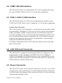
1
UNO-2052
GX1-300 UNO with 2xCAN, LAN,
USB, RS-232, 8 x Isolated DI/O, 2
x AI
User Manual
Copyright
The documentation and the software included with this product are copyrighted 2004 by Advantech Co., Ltd. All rights are reserved. Advantech
Co., Ltd. reserves the right to make improvements in the products
described in this manual at any time without notice. No part of this manual may be reproduced, copied, translated or transmitted in any form or
by any means without the prior written permission of Advantech Co., Ltd.
Information provided in this manual is intended to be accurate and reliable. However, Advantech Co., Ltd. assumes no responsibility for its use,
nor for any infringements of the rights of third parties, which may result
from its use.
Acknowledgements
IBM, PC/AT, PS/2 and VGA are trademarks of International Business
Machines Corporation.
Intel® and Pentium® are trademarks of Intel Corporation.
Microsoft Windows and MS-DOS are registered trademarks of
Microsoft Corp.
C&T is a trademark of Chips and Technologies, Inc.
All other product names or trademarks are properties of their respective
owners.
Part No. 2003205200
1st Edition
Printed in Taiwan
May 2004
UNO-2052 User Manual
ii
Product Warranty (2 years)
Advantech warrants to you, the original purchaser, that each of its products will be free from defects in materials and workmanship for two years
from the date of purchase.
This warranty does not apply to any products which have been repaired or
altered by persons other than repair personnel authorized by Advantech,
or which have been subject to misuse, abuse, accident or improper installation. Advantech assumes no liability under the terms of this warranty as
a consequence of such events.
Because of Advantech’s high quality-control standards and rigorous testing, most of our customers never need to use our repair service. If an
Advantech product is defective, it will be repaired or replaced at no
charge during the warranty period. For out-of-warranty repairs, you will
be billed according to the cost of replacement materials, service time and
freight. Please consult your dealer for more details.
If you think you have a defective product, follow these steps:
1.
Collect all the information about the problem encountered. (For
example, CPU speed, Advantech products used, other hardware
and software used, etc.) Note anything abnormal and list any
onscreen messages you get when the problem occurs.
2.
Call your dealer and describe the problem. Please have your manual, product, and any helpful information readily available.
3.
If your product is diagnosed as defective, obtain an RMA (return
merchandize authorization) number from your dealer. This allows
us to process your return more quickly.
4.
Carefully pack the defective product, a fully-completed Repair and
Replacement Order Card and a photocopy proof of purchase date
(such as your sales receipt) in a shippable container. A product
returned without proof of the purchase date is not eligible for warranty service.
5.
Write the RMA number visibly on the outside of the package and
ship it prepaid to your dealer.
iii
CE
This product has passed the CE test for environmental specifications. Test
conditions for passing included the equipment being operated within an
industrial enclosure. In order to protect the product from being damaged
by ESD (Electrostatic Discharge) and EMI leakage, we strongly recommend the use of CE-compliant industrial enclosure products.
FCC Class A
This equipment has been tested and found to comply with the limits for a
Class A digital device, pursuant to Part 15 of the FCC Rules. These limits
are designed to provide reasonable protection against harmful interference when the equipment is operated in a commercial environment. This
equipment generates, uses and can radiate radio frequency energy and, if
not installed and used in accordance with the instruction manual, may
cause harmful interference to radio communications. Operation of this
equipment in a residential area is likely to cause harmful interference in
which case the user will be required to correct the interference at his own
expense.
Technical Support and Assistance
Step 1. Visit the Advantech web site at www.advantech.com/support
where you can find the latest information about the product.
Step 2. Contact your distributor, sales representative, or Advantech's customer service center for technical support if you need additional
assistance. Please have the following information ready before
you call:
- Product name and serial number
- Description of your peripheral attachments
- Description of your software (operating system, version, application software, etc.)
- A complete description of the problem
- The exact wording of any error messages
UNO-2052 User Manual
iv
Packing List
Before setting up the system, check that the items listed below are
included and in good condition. If any item does not accord with the
table, please contact your dealer immediately.
The IPPC-9170 Series industrial panel PCs include the following models:
• Plug-in 2P female screw terminal for power
• Plug-in 10P female screw terminal for DI/O
• Plug-in 5P female screw terminal for AI
• AD509 temperature transducer
• Mini jumper 2.0mm * 10 pcs
• Y-type KB/MS cable
• Null-modem cable (UNO-2052CE only)
• DIN rail mounting kit * 2 pcs
• UNO-2000 Driver & Utility CD-ROM
• Advantech Warranty
v
UNO-2052 User Manual
vi
Contents
Chapter
1 UNO-2052 Overview ....................................... 2
1.1Introduction ....................................................................................
1.2Hardware Specifications.................................................................
1.3Safety Precautions ..........................................................................
1.4Chassis Dimensions........................................................................
2
2
4
5
Figure 1.1: Chassis Dimensions ..................................... 5
Chapter
2 Hardware Functionality ................................. 8
2.1UNO-2052 Peripherals ................................................................... 8
Figure 2.1:Front Panel of UNO-2052 ............................ 8
Figure 2.2:Rear Panel of UNO-2052 ............................. 9
2.2COM1: RS-232 Interface .............................................................
2.3CAN 1~CAN 2: CAN Interface ...................................................
2.4LAN: Ethernet Connector.............................................................
2.5Power Connector ..........................................................................
2.6PS/2 Keyboard and Mouse Connector .........................................
2.7USB Connector ............................................................................
2.8VGA Display Connector .............................................................
2.9RESET: Reset Button ...................................................................
2.10On-Board Isolated Digital Input .................................................
10
10
10
10
11
11
11
12
12
Figure 2.3:Pin Assignment of Digital Input Connector 12
Table 2.1:Digital Input Connector Signal Desc. .......... 12
Figure 2.4:Isolated Digital Input Conn.- Wet Contact . 13
Figure 2.5:Isolated Digital Input Conn.- Dry Contact . 14
2.11On-Board Isolated Digital Output .............................................. 15
Figure 2.6:Pin Assignment of Isolated DO. Conn. ...... 15
Table 2.2:Signal Desc. for Digital Output Connectors 15
Figure 2.7:Isolated Digital Output Connection ............ 15
2.12On-Board Analog Input .............................................................. 16
Figure 2.8:Analog Input Connector Pin Assignment ... 16
Table 2.3:Analog Input Conn. Signal Descriptions ..... 16
Figure 2.9:Milli Volt and Volt Input ........................... 16
Figure 2.10:Thermocouple Input ................................. 17
Figure 2.11:Process Current Input ............................... 17
Chapter
3 Initial Setup.................................................... 20
3.1Inserting a CompactFlash Card ....................................................
3.2Connecting the Power...................................................................
3.3Connecting to a Hard Disk ...........................................................
3.4BIOS Setup and System Assignments..........................................
Chapter
20
20
20
21
4 I/O Command Set.......................................... 24
4.1Introduction .................................................................................. 24
4.2Syntax ........................................................................................ 24
Table 4.1:UNO-2052 Command Set Table ................. 25
4.2.1%AANNTTCCFF.................................................................... 26
vii
Table of Contents
Figure 4.1:Data Format for 8-bit Parameter ............... 26
4.2.2%AANNTTCCFF ..................................................................... 27
Table 4.2:Input Range Codes (Type Code) ................. 28
Table 4.3:Baud Rate Codes ......................................... 28
4.2.3$AA2 ...................................................................................... 29
4.2.4$AA2 ...................................................................................... 30
4.2.5$AAF ...................................................................................... 30
4.2.6$AAM ...................................................................................... 31
4.2.7#AA ...................................................................................... 32
4.2.8#AA ...................................................................................... 33
4.2.9#AAN ...................................................................................... 34
4.2.10$AA0 ...................................................................................... 35
4.2.11$AA1 ...................................................................................... 36
4.2.12$AAB ...................................................................................... 37
4.2.13$AA3 ...................................................................................... 38
4.2.14$AA9 ...................................................................................... 39
4.2.15$AA6 ...................................................................................... 40
4.2.16#AABB ................................................................................... 41
4.2.17#AABB ................................................................................... 42
Appendix A
......................................................................... 44
A.1Board Connectors and Jumpers ................................................... 44
Figure A.1:UNO-2052 Conn. and Jmp. Loc. (T.View) 44
Figure A.2:UNO-2052 Conn. & Jmp. Loc. (B.View) . 45
Table A.1:UNO-2052 Connectors and Jumpers .......... 46
A.2RS-232 Standard Serial Port (COM1) ......................................... 47
Table A.2:RS-232 Standard Serial Port Pin Assig. ..... 47
A.3CAN Serial Port Pin Assignment ................................................ 48
Table A.3:CAN Port Pin Assig. (CAN1~CAN2) ........ 48
A.3.1Termination Resistor Setup ..................................................... 48
A.3.2CAN Signal Wiring ................................................................. 49
Table A.4:UNO-2052 DTE Terminal DTE ................ 49
A.4Ethernet RJ-45 Connector (LAN1).............................................. 49
Table A.5:Ethernet RJ-45 Conn. Pin Assignments ...... 49
A.5Phoenix Power Connector (PWR) .............................................. 50
Table A.6:Phoenix Power Conn. Pin Assignments ..... 50
A.6PS/2 Keyboard and Mouse Connector......................................... 50
Table A.7:Keyboard and Mouse Conn. Pin Assig. ...... 50
A.7USB Connector (USB1) .............................................................. 51
Table A.8:USB Connector Pin Assignments ............... 51
A.8VGA Display Connector ............................................................. 51
Table A.9:VGA Adaptor Cable Pin Assignment ......... 51
A.9CompactFlash Master/Slave Jumper Setting (JP3) ..................... 52
MIC-3780 User Manual
viii
CHAPTER
1
2
UNO-2052 Overview
This chapter gives background information on the UNO-2052. It shows you
the UNO-2052 overview and specifications.
Sections include:
• Introduction
• Hardware Specifications
• Safety Precautions
• Chassis Dimensions
Chapter 1 UNO-2052 Overview
1.1 Introduction
UNO-2052 is an embedded Application Ready Platform (ARP) that can
shorten your development time and offer rich networking interfaces to
fulfill extensive needs in different kind of projects. The Advantech Universal Network Controller (UNO-2000 series) is designed for providing
services on a network enabled Application Ready Platform.
Leveraging field-approved and worldwide-accepted OS technology,
Advantech UNO-2000 series provides a Windows CE .NET ready solution, and supports several standard networking interfaces, such as Ethernet, Wireless LAN, RS-232/422/485 and more. Because of its openness,
great expansion capability and reliable design (fanless and diskless), the
Advantech UNO-2000 series are ideal embedded platforms to implement
custom applications for diversified applications.
1.2 Hardware Specifications
• CPU: NS Geode GX1-300 MHz, 64/128 MB SDRAM on board
• VGA/Keyboard/Mouse: DB-15 VGA Connector, PS/2 keyboard &
mouse
• Serial Port: 1 × standard RS-232
- Speed: RS-232: 50 ~ 115.2 Kbps
• USB Interface: One USB port, USB OpenHCI, Rev. 1.0 compliant
• LAN: One 10/100 Base-R RJ-45 Ports
• CAN: Dual isolated CAN 2.0B interfaces.
- CAN controller: SJA-1000
- CAN transceiver: 82C250
- Signal support: CAN-L, CAN-H
- CAN isolation: 1000 VDC
• 4-ch isolated digital input:
- 2,000 VDC isolation, 2,000 VDC ESD protection and 70 VDC overvoltage protection
- 0 ~ 50 VDC input range
- Digital input level
UNO-2052 User Manual
2
• Dry Contact:
Logic level 0: Close to GND
Logic level 1: Open
• Wet Contact:
Logic level 0: +2V max
Logic level 1: +4V~+50V
• 4-ch isolated Digital Output:
- 2,000 VDC isolation and 200 mA max / channel sink current
- Keep output status after system hot reset
- 5 ~ 30 VDC output range
Open collector to 30 V
30 mA max. load
Power dissipation: 300 mW
• 2-ch Analog Input:
-Input type: Thermocouple: J/K/T/E-type.
-Input range: +-15 mV, +-50 mV, +-100 mV, +- 500 mV, +-1 V, +-2.5
V, +-20 mA
-T/C type and temperature range:
J 0 ~ 760° C
K 0 ~ 1370° C
T -100 ~ 400° C
E 0 ~ 1000° C
• SSD: One internal Type I / Type II CompactFlash card slot
• HDD: HDD extension kit offered for installation of one standard 2.5''
HDD.
• Watchdog Timer: Programmable.
• LED: Power LED, IDE LED and one programmable diagnostic LED
and buzzer.
• Power Supply: 9~36 VDC
• Anti-Shock: 20G@DIN IEC 68 section 2-27, half sine, 11ms
50G@Wall/Panel IEC 68 section 2-27, half sine, 11ms.
• Anti-Vibration: 2G w/ CF@IEC 68 section 2-6, sine, 5~500Hz, 1
Oct./min, 1hr/axis.
1G w/ HDD@IEC 68 section 2-6, sine, 12~300Hz, 1 Oct./min, 1hr/
axis.
• Operating Temperature: -10~55° C @ 5~85% related humidity.
• Related Humidity: 95% @ 40° C.
3
Chapter 1
• Power Consumption: 0.6 A max under +24 V power input or 1.2 A
max under +12 V power input
• Power Requirement: 1 A typical under +24 V power input or 1.5 A
typical under +12 V power input
• Operating Temperature: -10 ~55° C (14 ~ 131° F)
• Chassis Size: (WxLxH) 188.8 x 106.5 x 35.5 mm (7.5" × 4.2" × 1.4")
• Weight: 0.8 kg
1.3 Safety Precautions
The following sections tell how to make each connection. In most cases,
you will simply need to connect a standard cable.
Warning!
Always disconnect the power cord from your chassis whenever you are working on it. Do not connect
while the power is on. A sudden rush of power can
damage sensitive electronic components. Only
experienced electronics personnel should open the
chassis.
Caution!
Always ground yourself to remove any static electric charge before touching UNO-2052. Modern
electronic devices are very sensitive to static electric charges. Use a grounding wrist strap at all
times. Place all electronic components on a staticdissipative surface or in a static-shielded bag.
UNO-2052 User Manual
4
1.4 Chassis Dimensions
Figure 1.1: Chassis Dimensions
5
Chapter 1
UNO-2052 User Manual
6
CHAPTER
2
2
Hardware Functionality
This chapter shows how to set up the
UNO-2052’s hardware functions,
including connecting peripherals,
switches and indicators.
Sections include:
• UNO-2052 Peripherals
• COM1 RS-232 Interface
• CAN1~CAN2: CAN Interface
• LAN: Ethernet Connector
• Power Connector
• PS/2 Mouse and Keyboard Connector
• USB Connector
• VGA Display Connector
• Reset Button
• On-Board Isolated Digital Input
• On-Board Isolated Digital Output
• On-Board Analog Input
Chapter 2 Hardware Functionality
2.1 UNO-2052 Peripherals
The following two figures show the connectors on UNO-2052. The following sections give you detail information about function of each
peripheral.
Figure 2.1: Front Panel of UNO-2052
UNO-2052 User Manual
8
CN5
Figure 2.2: Rear Panel of UNO-2052
9
Chapter 2
2.2 COM1: RS-232 Interface
The UNO-2052 offers one standard RS-232 serial communication interface port (COM1). Please refer to A.2 for the pin assignments.
2.3 CAN 1~CAN 2: CAN Interface
The UNO-2052 offers two CAN serial communication interface ports.
COM3 and COM4. Please refer to Appendix A.3 for the pin assignments.
Control Area Network
The CAN (Control Area Network) is a serial bus system specially suited
for networking “intelligent” I/O devices as well as sensors and actuators
within a machine or plant. Characterized by its multi-master protocol,
real-time capability, error correction, high noise immunity, and the existence of many different silicon components, the CAN serial bus system,
originally developed by Bosch for use in automobiles, is increasingly
being used in industrial automation.
For further information about CAN controllers, please refer to the data
sheet of JIA-1000.
2.4 LAN: Ethernet Connector
The UNO-2052 is equipped with a Realtek RTL8139C Ethernet LAN
controller that is fully compliant with IEEE 802.3u 10/100Base-T
CSMA/CD standards. The Ethernet port provides a standard RJ-45 jack
on the board, and LED indicators on the front side shows its link (Green
LED) and active (Yellow LED) status.
2.5 Power Connector
The UNO-2052 comes with a Phoenix connector to provide a 9~36 VDC
external power input, and features reversed wiring protection. Therefore,
it will not cause any damage to the system in the case of reversed wiring
of ground line and power line.
UNO-2052 User Manual
10
2.6 PS/2 Keyboard and Mouse Connector
The UNO-2052 provides a PS/2 keyboard and PS/2 mouse connector. A
6-pin mini-DIN connector is located on the rear panel of the UNO-2052.
The UNO-2052 comes with an adapter to convert from the 6-pin miniDIN connector to two 6-pin mini-DIN connectors for PS/2 keyboard and
PS/2 mouse connection. Please refer to Appendix A.5 for its pin assignments.
2.7 USB Connector
The USB connector is used for connecting any device that conforms to
the USB interface. Many recent digital devices conform to this standard.
The USB interface supports Plug and Play, which enables you to connect
or disconnect a device whenever you want, without turning off the computer.
The UNO-2052 provides two connectors for USB interfaces, which gives
complete Plug & Play, and hot swapping for up to 127 external devices.
The USB interface complies with USB UHCI, Rev. 1.1. The USB interface can be disabled in the system BIOS setup. Please refer to Appendix
A.6 for its pin assignments.
2.8 VGA Display Connector
The UNO-2052 provides a VGA controller (Chipset: VIA Twister chip
with Integrated S3 Savage4 2D/3D/Video accelerator) for a high resolution VGA interface. It supports VGA and VESA, up to 1280 x 1024 @ 8
bpp and 1024 x 768 @ 16bpp resolution, and up to 32 MB shared memory. The VGA interface is reserved for system testing and debugging. The
UNO-2052's JP8 is a 6-pin mini connector and CN7 is a 15-pin connector
for a VGA monitor. A VGA cable is attached to convert from a 6-pin mini
connector to a standard VGA connector. You can choose one of the VGA
interfaces for system testing and debugging. Pin assignments for VGA
display are described in Appendix A.7.
11
Chapter 2
2.9 RESET: Reset Button
Press the "Reset" button to activate a reset function.
2.10 On-Board Isolated Digital Input
The UNO-2052 has four isolated digital input channels designated
DI0~DI3.
Pin Assignment
The connector type of UNO-2052 is a plug-in screw terminal block that
enables you to connect to field I/O devices directly without additional
accessories. Figure 2-3 and Table 2-1 shows its pin assignment as well as
signal descriptions.
DI0 DI1 DI2 DI3
COM
IsolatedDI
Figure 2.3: Pin Assignment of Digital Input Connector
Table 2.1: Digital Input Connector Signal Descriptions
Signal Name Reference
Direction Description
DI <0…3>
COM
Input
Isolated digital input signals
COM
-
Input
Common ground
UNO-2052 User Manual
12
Isolated Inputs
Each of the isolated digital input channels accepts 10 ~ 50 VDC inputs,
and bi-directional inputs. It means that you can apply positive or negative
voltage to an isolated input pin (Vin). All four channels share one common pin (COM). Figure 2.4 shows how to connect an external input
source to one of the UNO-2052’s isolated input channels.
VCC
2K
DI
0~+50V DC
COM
Digital GND
Digital GND
Figure 2.4: Isolated Digital Input Connection- Wet Contact
13
Chapter 2
VCC
2K
DI
COM
Digital GND
Figure 2.5: Isolated Digital Input Connection- Dry Contact
UNO-2052 User Manual
14
2.11 On-Board Isolated Digital Output
The UNO-2052 has four isolated digital output channels designated
DO0~DO3.
Pin Assignment
The connector type of UNO-2052 is a plug-in screw terminal block that
enables you to connect to field I/O devices directly without additional
accessories. Figure 2-6 and Table 2-2 shows its pin assignment as well as
signal description.
DO0 DO1 DO2 DO3 COM
IsolatedDO
Figure 2.6: Pin Assignment of Isolated Digital Output Connector
Table 2.2: Signal Descriptions for Digital Output Connectors
Signal Name Reference
Direction Description
DO <0…3>
COM
Output
Isolated digital output signals
COM
-
Input
Common ground
+Vs
DO
R2
+
SSR
-
AC
COM
Digital GND
Digital GND
Open Collector
Figure 2.7: Isolated Digital Output Connection
15
Chapter 2
2.12 On-Board Analog Input
The UNO-2052 has two analog input channels designated AI0, AI1.
Pin Assignment
The connector type of UNO-2052 is plug-in screw terminal block that
enables you to connect to field I/O devices directly without additional
accessories. Figure 2-8 and Table 2-3 shows its pin assignment as well as
signal description.
AI0+ AI0- AI1+ AI1-
CJC.1 CJC.2
AI
Figure 2.8: Analog Input Connector Pin Assignment
Table 2.3: Analog Input Connector Signal Descriptions
Signal Name Direction Description
AI <0,1>
Input
CJC <1,2>
Analog input signals
CJC sensor for calibration
AI+
Hi
+
V mV/V
-
AI-
Lo
Figure 2.9: Milli Volt and Volt Input
UNO-2052 User Manual
16
AI+
Hi
+
120 ohm
Iin 0~20mA
JP5/JP6
-
AI-
Lo
Figure 2.10: Thermocouple Input
AI+
T/ C
AI-
Figure 2.11: Process Current Input
Jumper
Description
JP5
Closed, process current input for AI0
Open, volt or thermocouple input for AI0
JP6
Closed, process current input for AI1
Open, volt or thermocouple input for AI1
17
Chapter 2
UNO-2052 User Manual
18
CHAPTER
3
2
Initial Setup
This chapter provides information on
how to setup UNO-2052.
Sections include:
• Inserting a CompactFlash Card
• Connecting the Power
• Connecting to a Hard Disk
• BIOS Setup and System Assignments
Chapter 3 Initial Setup
3.1 Inserting a CompactFlash Card
The procedure for installing a CompactFlash card into the UNO-2052 is
as follows, please follows these steps carefully.
Step 1: Remove the power cord.
Step 2: Unscrew the four screws from the rear panel of the UNO-2052.
Step 3: Remove the rear panel.
Step 4: Plug a CompactFlash card with the user’s OS and application program into a CompactFlash card slot on the board.
Step 5: Screw back the rear panel with the four screws.
3.2 Connecting the Power
Connect the UNO-2052 to a 9~36 VDC power source. The power source
can either be from a power adapter or an in-house power source.
3.3 Connecting to a Hard Disk
The procedure for installing a hard disk into the UNO-2052 is as follows,
please follows these steps carefully.
Step 1: Remove the power cord.
Step 2: Unscrew the four screws from the rear panel of the UNO-2052.
Step 3: Remove the rear panel.
Step 4: Connect an IDE flat cable to the primary (recommended) or secondary IDE connector, then connect the other side of the connector to the
hard disk.
Step 5: Screw back the rear panel with the four screws.
UNO-2052 User Manual
20
3.4 BIOS Setup and System Assignments
UNO-2052 uses the Advantech SOM-2353 CPU module. Further information about the SOM-2353 CPU module can be found in the SOM-2353
user manual.
Please note that you can try to “LOAD BIOS DEFAULTS” from the
BIOS Setup manual if the UNO-2052 does not work properly.
21
Chapter 3
UNO-2052 User Manual
22
4
CHAPTER
2
I/O Command Set
This chapter introduces the command
sets used for digital input, digital output
and analog input with UNO-2052.
Chapter 4 I/O Command Set
4.1 Introduction
To avoid communication conflicts when several devices try to send data
at the same time, all actions are instigated by the UNO-2052. The basic
form is a command/response protocol with the UNO-2052 initiating the
sequence. When UNO-2052 is not transmitting, other devices are in listening mode. All of UNO-2052’s command sets follow the Advantech
ADAM command set format.
4.2 Syntax
The syntax of the Advantech ADAM command set is listed as below:
[delimiter character] [address*] [command] [data] [checksum**] [carriage return]
Every command begins with a delimiting character, which are defined
below:
$: dollar sign
#: pound sign
%: percentage sign
@: at sign
The delimiter character is followed by a two-character address (hexadecimal) that specifies the UNO-2052. The I/O address of UNO-2052 is
defined as (0x01)H. The actual two character command follows the
address. Depending on the command, an optional data segment follows
the command string. An optional two character checksum may be
appended to the total string; but the checksum is disabled in UNO-2052.
Every command is terminated by a carriage return (cr).
* The I/O address of UNO-2052 is defined as (0x01)H.
** The checksum is disabled in UNO-2052
UNO-2052 provides an internal serial communication port (COM2). You
can configure the digital input, digital output and analog input function of
UNO-2052 by COM2. The baud rate of COM2 can support 115200 bps,
57600 bps, 38400 bps, 19200 bps and 9600 bps.
UNO-2052 User Manual
24
Table 4.1: UNO-2052 Command Set Table
Command
Syntax
Command
Name
Description
%AANNTTCCFF
Configuration
Sets input range, integration time
for a specified analog input module
$AA2
Configuration
Status
Returns the configuration parameters for the specified analog input
module
$AAF
Read Firmware Version
Returns the firmware version
source code from the specified
analog input module
$AAM
Read Module
Name
Returns the module name from the
specified analog input module
#AA
Analog Data In
Returns the input value from a
specified analog input module in
the currently configured data format
#AAN
Read Analog
Input from
Channel N
Returns the input value from channel number n of the specified analog input module
$AA0
Span Calibration
Calibrate the analog input module
to correct for gain errors
$AA1
Offset Calibration
Calibrate the analog input module
to correct for offset errors
$AAB
Open Thermocouple Detection
Ask the module to respond
whether the thermocouple is open
or closed.
$AA3
CJC Status
Returns the value of the CJC sensor for a specified analog input
module
$AA9
CJC Offset
Calibration
Calibrates the CJC sensor for offset errors
$AA6
Digital Data In
Returns the values of digital I/O
channels of the addressed module
#AABB(data)
Digital Data
Out
Write specified values to either a
single channel or all channels
simultaneously
25
Chapter 4
4.2.1 %AANNTTCCFF
Name: Configuration
Description: Sets address, input range, baud rate, data format, checksum
status, and/or integration time for an analog input module.
Syntax:
%AANNTTCCFF(cr)
% is a delimiter character.
AA(01) represents the 2-character hexadecimal address of the analog
input module you want to configure.
NN represents the new hexadecimal address of the analog input module.
The address of UNO-2052 must be 01h.
TT represents the type (input range) code.
CC represents the baud rate code.
FF is a hexadecimal number that equals the 8-bit parameter representing
the data format, checksum status and integration time. The layout of the
8-bit parameter is shown in figure 4-1. Bits 2 through 5 are not used and
are set to 0.
(cr) is the terminating character, carriage return (0Dh)
7
6
5
Checksum status
0: Disabled
1: Enabled
4
3
2
1
Not used
0
DataFormat
00: Engineering Unit
Integrationtime
0: 50 ms (Operation under 60 MHz power)
1: 60 ms (Operation under 50 MHz power)
Figure 4.1: Data Format for 8-bit Parameter
UNO-2052 User Manual
26
4.2.2 %AANNTTCCFF
Response: !AA(cr) if the command is valid.
?AA(cr) if an invalid parameter was entered or if the INIT* terminal was
not grounded when attempting to change baud rate or checksum settings.
There is no response if the module detects a syntax error or communication error or if the specified address does not exist.
! delimiter character indicates a valid command was received.
? delimiter character indicates the command was invalid
AA (01) represents the 2-character hexadecimal address of an analog
input module.
(cr) is the terminating character, carriage return (0Dh)
Example:
command: %0101050600(cr)
response: !01(cr)
The UNO-2052 module with address 01h is configured to: input range
±2.5 V, baud rate 9600, integration time 50 ms (60 Hz), engineering units
data format and no checksum checking or generation.
The response indicates that the command was received.
Wait 1 second to let the new configuration settings take effect before issuing a new command to the module.
NOTICE:
An analog input module requires a maximum of 1
second to perform auto calibration and ranging
after it is reconfigured. During this time span, the
module cannot be addressed to perform any
other actions.
27
Chapter 4
Table 4.2: Input Range Codes (Type Code)
Input Range
Code (Hex)
Input Range for 4011,4011D,4018,4018+,4018M
00
± 15 mV
01
± 50 mV
02
± 100 mV
03
± 500 mV
04
±1V
05
± 2.5 V
06
± 20 mA
0E
Type J Thermocouple 0 to 760° C
0F
Type K Thermocouple 0 to 1370° C
10
Type T Thermocouple -100 to 400° C
11
Type E Thermocouple 0 to 1370° C
Table 4.3: Baud Rate Codes
Baud Rate Code (hex) Baud Rate
06
9600 bps
07
19.2 kbps
08
38.4 kbps
09
57.6 kbps
0A
115.2Kbps
UNO-2052 User Manual
28
4.2.3 $AA2
Name: Configuration Status
Description: The command requests the return of the configuration data
from the analog input module at address AA.
Syntax: $AA2(cr)
$ is a delimiter character.
AA (01) represents the 2-character hexadecimal address of the analog
input module that you want to
interrogate.
2 is the Configuration Status command.
(cr) is the terminating character, carriage return (0Dh).
Response: !AATTCCFF(cr) if the command is valid.
?AA(cr) if an invalid operation was entered.
There is no response if the module detects a syntax error or communication error or if the specified address does not exist.
! delimiter character indicates a valid command was received.
? delimiter character indicates the command was invalid.
AA (01) represents the 2-character hexadecimal address of an analog
input module.
TT represents the type code. Type code determines the input range.
CC represents the baud rate code.
FF is a hexadecimal number that equals the 8-bit parameter that represents the data format, checksum status and integration time . The layout
of the 8-bit parameter is shown in figure 4-1. Bits 2 to 5 are not used, and
are set to 0.
(cr) is the terminating character, carriage return (0Dh).
(Also see the %AANNTTCCFF configuration command)
29
Chapter 4
4.2.4 $AA2
Example:
command: $012(cr)
response: !01050600(cr)
The command asks the analog input module at address (01)H to send its
configuration data.
The analog input module at address (01)H responds with an input range
of 2.5 volts, a baud rate of 9600 bps, an integration time of 50 ms (60 Hz),
engineering units are the currently configured data format, and no checksum function or checksum generation.
4.2.5 $AAF
Name: Read Firmware Version
Description: The command requests the analog input module at address
AA to return the version code of its firmware
Syntax: $AAF (cr)
$ is a delimiter character.
AA (01) represents the 2-character hexadecimal address of the analog
input module that you want to
interrogate.
F identifies the version command.
(cr) is the terminating character, carriage return (ODh)
Response: !AA(Version)(cr) if the command is valid.
There is no response if the module detects a syntax error or communication error, or if the specified address does not exist.
! is a delimiter character indicating a valid command was received.
AA (01) represents the 2-character hexadecimal address of an analog
input module.
(Version) is the version code of the module’s firmware at address AA.
(cr) is the terminating character, carriage return (ODh).
UNO-2052 User Manual
30
4.2.6 $AAM
Name Read Module Name
Description: The command requests the analog input module at address
AA to return its name
Syntax: $AAM (cr)
$ is a delimiter character.
AA (01) represents the 2-character hexadecimal address of the analog
input module that you want to
interrogate.
M is the Read Module Name command.
(cr) is the terminating character, carriage return (ODh)
Response: !AA(Module Name)(cr) if the command is valid.
There is no response if the module detects a syntax error or communication error, or if the specified address does not exist.
! is a delimiter character indicating a valid command was received.
AA (01) represents the 2-character hexadecimal address of an analog
input module.
(Module Name) is the name of the module at address AA.
(cr) is the terminating character, carriage return (ODh).
31
Chapter 4
4.2.7 #AA
NameAnalog Data In
Description: The command will return the input value from a specified
(AA) module in the currently configured data format.
Syntax: #AA(cr)
# is a delimiter character.
AA (01) represents the 2-character hexadecimal address of an analog
input module.
(cr) is the terminating character, carriage return (0Dh).
Response: >(data)(cr)
There is no response if the module detects a syntax error or communication error or if the specified address does not exist.
> is a delimiter character.
(data) is the input value in the configured data format of the interrogated
module. (For data formats, see Appendix B).
(cr) is the terminating character, carriage return (0Dh).
Example: command:#01(cr)
response:+1.8222+1.8220(cr)
The command interrogates the analog input module at address 01h for its
input values of all channels.
The analog input module responds with channels from 0 to 1 with
+1.8222 volts and +1.8220 volts.
UNO-2052 User Manual
32
4.2.8 #AA
NOTICE:
When modules measure Thermocouple or RTD
input values that are outside their configured
range, they will send data that implies input out of
bounds. The next table shows the values that the
modules will return, depending on the configured
data format and if the input value falls under or
exceeds the configured range.
Only when modules are configured for Thermocouple will this “input out of bounds” warning
occur. When analog input modules measure voltage or current that falls outside the configured
range, they will return the actual measured input!
In the next example the target module is
configured for an input range of T/C type J (Input
range: 0 - 760° C) and for a data format in engineering units. The module measures an input
value of 820° C.
Example: command: #01(cr)
response: >+9999(cr)
By returning a high value, +9999, the module at address 01h indicates
that the measured input value exceeds the configured range.
33
Chapter 4
4.2.9 #AAN
Name: Read Analog Input from Channel N
Description: The command will return the input value from one of the
eight channels of a specified (AA) module in the currently configured
data format.
Syntax: #AAN(cr)
# is a delimiter character.
AA (01) represents the 2-character hexadecimal address of the analog
input module.
N identifies the channel you want to read. The value can range from 0 to 1
for UNO-2052.
(cr) is the terminating character, carriage return (0Dh).
Response: >(data)(cr)
There is no response if the module detects a syntax error or communication error or if the specified address does not exist.
> is a delimiter character.
(data) is the input value of the channel number N. Data consists of a + or
- sign followed by five decimal digits with a fixed decimal point.
(cr) is the terminating character, carriage return (0Dh).
Example: command: #010(cr)
response: >+1.4567(cr)
The command requests the analog input module at address 01h to return
the input value of channel 0.
The analog input module responds that the input value of channel 0 is
equal to +1.4567 volts.
UNO-2052 User Manual
34
4.2.10 $AA0
Name: Span Calibration
Description: Calibrates an analog input module to correct for gain errors.
Syntax: $AA0(cr)
$ is a delimiter character.
AA (01) represents the 2-character hexadecimal address of the analog
input module which is to be calibrated.
0 represents the span calibration command.
(cr) is the terminating character, carriage return (0Dh).
Response: !AA(cr) if the command was valid.
?AA(cr) if an invalid operation was entered.
There is no response if the module detects a syntax error or communication error or if the specified address does not exist.
! delimiter character indicates a valid command was received.
? delimiter character indicates the command was invalid.
AA (01) represents the 2-character hexadecimal address of the analog
input module.
(cr) represents terminating character, carriage return (0Dh).
In order to successfully calibrate an analog input module’s input range, a
proper calibration input signal should be connected to the analog input
module (channel 0 and 1) before and during the calibration.
NOTICE:
An analog input module requires a maximum of 1
second to perform auto calibration and ranging after
it received a Span Calibration command. During
this interval, the module cannot be addressed to
perform any other actions.
35
Chapter 4
4.2.11 $AA1
Name: Offset Calibration.
Description: Calibrates an analog input module to correct for offset
errors.
Syntax: $AA1(cr)
$ is a delimiter character.
AA (01) represents the 2-character hexadecimal address of the analog
input module you want to calibrate.
1 represents the offset calibration command.
(cr) is the terminating character, carriage return (0Dh).
Response: !AA(cr) if the command is valid.
?AA(cr) if an invalid operation was entered.
There is no response if the module detects a syntax error or communication error or if the specified address does not exist.
! delimiter character indicates a valid command was received.
? delimiter character indicates the command was invalid.
AA (01) represents the 2-character hexadecimal address of the analog
input module.
(cr) represents terminating character, carriage return (0Dh).
In order to successfully calibrate an analog input module’s input range, a
proper calibration input signal should be connected to the analog input
module (channel 0 and 1) before and during the calibration.
NOTICE:
An analog input module requires a maximum of 1
second to perform auto calibration and ranging
after it received an Offset Calibration command .
During this interval, the module can not be
addressed to perform any other actions.
UNO-2052 User Manual
36
4.2.12 $AAB
Name: Open Thermocouple Detection
Description: Asks the module to respond whether the thermocouple is
open or not.
Syntax: $AAB(cr)
$ is a delimiter character
AA (01) represents the 2-character hexadecimal address of the analog
input module to be detected.
B is the channel diagnose command.
(cr) is the terminating character, carriage return (0Dh)
Response:
!AANN(cr) if the command is valid.
?AA(cr) if an invalid command was issued.
There is no response if the module detects a syntax error or communication error of if the specified address does not exist.
! delimiter character indicates a valid command was received.
? delimiter character indicates the command was invalid.
AA (01) represents the 2-character hexadecimal address of the analog
input module.
NN (range 00-03) is a hexadecimal number that equals the 8-bit parameter, representing the status of analog input channels. Bit value 0 means
normal status; and bit value 1 means channel open wiring.
(cr) is the terminating character, carriage return (0Dh)
37
Chapter 4
4.2.13 $AA3
Name: CJC Status command
Description: Instructs the addressed analog input module to read its CJC
(Cold Junction Compensation) sensors and return the acquired data.
Syntax: $AA3(cr)
$ is a delimiter character.
AA (01) represents the 2-character hexadecimal address of the analog
input module which contains the CJC Status you wish to retrieve.
3 is CJC Status command.
(cr) is the terminating character, carriage return (0Dh).
Response: >data(cr) if the command is valid.
?AA(cr) if an invalid command was issued.
There is no response if the module detects a syntax error or communication error or if the specified address does not exist.
! delimiter character indicates a valid command was received.
? delimiter character indicates the command was invalid
AA (01) represents the 2-character hexadecimal address of an analog
input module.
(data) is the value that is retrieved by the module by reading its CJC sensor. The data format, in degrees Celsius, consists an “+” or “-” sign followed by five decimal digits and a fixed decimal point. The resolution of
the data is 0.1° C.
(cr) is the terminating character, carriage return (0Dh).
Example: command: $013(cr)
response: >+0036.8(cr)
The command request the analog input module at address 01h to read its
CJC sensor and return the data. The analog input module at address 01h
responds with: 36.8° C.
UNO-2052 User Manual
38
4.2.14 $AA9
Name: CJC Offset Calibration
Description: Calibrates an analog input module to adjust for offset errors
of its CJC (Cold Junction Compensation) sensors.
Syntax: $AA9S(number of counts)(cr).
$ is a delimiter character.
AA (01) represents the 2-character hexadecimal address of the analog
input module which contains the CJC Status you wish to retrieve.
9 is CJC Status command.
S sign, + or -, indicates whether to increase or decrease the CJC offset
value.
(number of counts) a four character hexadecimal “count” value. Each
count equals approximately 0.009° C. The value can range from 0000 to
FFFF.
(cr) is the terminating character, carriage return (0Dh).
Response: !AA(cr) if the command is valid.
?AA(cr) if an invalid command was issued.
There is no response if the module detects a syntax error or communication error or if the specified address does not exist.
! delimiter character indicates a valid command was received.
? delimiter character indicates the command was invalid.
AA (01) represents the 2-character hexadecimal address of an analog
input module.
(cr) is the terminating character, carriage return (0Dh).
Example: command: $019+0042(cr)
response: !01(cr)
The command increases the CJC offset value of the analog input module
at address 01h with 66 counts (42 hex) which equals about 0.6° C.
NOTICE:
An analog input module requires a maximum of
2 seconds to perform auto calibration and ranging after it received an CJC Calibration command . During this interval, the module can not
be addressed to perform any other actions.
39
Chapter 4
4.2.15 $AA6
Name: Digital Data In
Description: This command requests that the specified (AA) module
returns the status of its digital input channels and returns a readback value
of its digital output channels.
Syntax: $AA6(cr)
$ is a delimiter character.
AA (01) represents the 2-character hexadecimal address of the digital I/O
module.
6 is the Digital Data In command.
(cr) is the terminating character, carriage return (0Dh).
Response: !(dataOutput)(dataInput)00(cr)
if the command was valid.
?AA(cr) if an invalid command has been issued.
There is no response if the module detects a syntax error or communication error or if the specified address does not exists.
! delimiter character indicating a valid command was received.
? delimiter character indicating the command was invalid.
AA (01) represents the 2-character hexadecimal address of the digital I/O
module that is responding.
(dataOutput) two-character hexadecimal value which either is the readback of a digital output channel or a relay.
(dataInput) two-character hexadecimal value representing the input values of the digital I/O module.
(cr) is the terminating character, carriage return (0Dh).
Example: command: $016(cr)
response: !090300(cr)
The first two characters of the response, value 09h (00001001), indicate
that digital output channels 0 and 3 are ON, channels 1, 2, are OFF. The
second two characters of the response, value 03h (00000010), indicate
that digital input channels 0 and 1 are HIGH, channels 2, 3 are LOW.
UNO-2052 User Manual
40
4.2.16 #AABB
Name: Digital Data Out
Description: The command either sets a single digital output channel or
sets all digital output channels simultaneously.
Syntax: #AABB(data)(cr)
# is a delimiter character.
AA (01) represents the 2-character hexadecimal address of the digital I/O
module you want to set its output value.
BB is used to indicate whether all channels will be set or a single channel
will be set. In the last case BB also indicates which channel. Writing to all
channels (write a byte): both characters should be equal to zero (BB=00).
Writing to a single channel (write a bit): First character is 1, second character indicates channel number which can range from 0 to 3.
(data) is the hexadecimal representation of the digital output value(s).
When writing to a single channel (bit) the first character is always 0.
The value of the second character is either 0 or 1.
When writing to all channels (byte), both characters are significant
(range 00h-0Fh). The digital equivalent of these two hexadecimal characters represent the channels values.
41
Chapter 4
4.2.17 #AABB
Response: >(cr) if the command was valid.
?AA(cr) if an invalid command has been issued.
There is no response if the module detects a syntax error or communication error or if the specified address does not exists.
> delimiter character indicating valid command was received.
? delimiter character indicating the command was invalid.
AA (01) represents the 2-character hexadecimal address of the digital I/O
module that is responding.
(cr) is the terminating character, carriage return (0Dh).
Examples: command: #010005(cr)
response: >(cr)
An output byte with value 05h (00000101) is sent to the digital I/O module at address (01)H. Its channels 0 and 2 will be set to ON. Other channels are set to OFF.
command: #011201(cr)
response: >(cr)
An output bit with value 1 is sent to channel 2 of a digital I/O module at
address 01h.
Channel two of the digital I/O module is set to ON.
UNO-2052 User Manual
42
APPENDIX
A
2
System Settings
This chapter provides information on
the system settings of UNO-2052.
Sections include:
• Board Connectors and Jumpers
• RS-232 Standard Serial Port
• CAN Serial Port
• Ethernet RJ-45 Connector
• Phoenix Power Connector (PWR)
• PS/2 Keyboard and Mouse Connector
• USB Connector
• VGA Display Connector
• CompactFlash Master/Slave Jumper
Setting
Appendix A
A.1 Board Connectors and Jumpers
There are connectors and jumpers on the UNO-2052 board. The
following sections tell you how to configure the UNO-2052 hardware setting. Figure A-1 and figure A-2 show the locations of UNO2052 connectors and jumpers.
Figure A.1: UNO-2052 Connector and Jumper Location (Top View)
UNO-2052 User’s Manual
44
CN5
Figure A.2: UNO-2052 Connector and Jumper Location (Bottom View)
45
Appendix A
Table A.1: UNO-2052 Connectors and Jumpers
CON1
COM1 standard RS-232 port
P1
CAN 1 DB-9 connector
P2
CAN 2 DB-9 connector
JP3
CompactFlash IDE Primary Master/Slave jumper
JP4
Isolated digital input and digital output connector
JP5
Analog input connector
JP12
Termination resistor for CAN 1 and CAN 2
Power
Phoenix power connector
CN4
Internal CompactFlash card slot
DB5
Power IDE LED
DB6
Power LED
DB7
Diagnostic LED
KM1
PS2 keyboard and mouse connector
CON1
USB connector
LAN1
Ethernet RJ-45 connector
VGA1
VGA DB-15 connector
J1
Reset button
UNO-2052 User’s Manual
46
A.2 RS-232 Standard Serial Port (COM1)
1 2 3 4 5
6 7 8 9
Table A.2: RS-232 Standard Serial Port Pin Assignments
Pin
RS-232 Signal Name
1
DCD
2
RxD
3
TxD
4
DTR
5
GND
6
DSR
7
RTS
8
CTS
9
RI
47
Appendix A
A.3 CAN Serial Port Pin Assignment
Table A.3: CAN Port Pin Assignments (CAN1~CAN2)
Pin
CAN Signal Name
1
N/A
2
CAN-L
3
GND
4
N/A
5
N/A
6
N/A
7
CAN-H
8
N/A
9
N/A
1
CAN-L 2
GND 3
4
5
6
7 CAN-H
8
9
A.3.1 Termination Resistor Setup
Terminal resistors are factory installed to allow for impedance matching.
These resistors can be enabled by utilizing JP12 (shown below). The
value of the resistor should equal the characteristic impedance of the signal wires (approximately 120 ohms). The following figure shows resistor
placements.
Enable Termination Resistor for CAN1 Port
JP12
Enable Termination Resistor for CAN2 Port
JP12
UNO-2052 User’s Manual
48
A.3.2 CAN Signal Wiring
The CAN standard supports half-duplex communication. This means that
just two wires are used to transmit and receive data.
D.T.E
CANTransceiver
CAN-H
D.T.E
CANTransceiver
CAN-L
CAN-H
D.T.E
CANTransceiver
CAN-L
CAN-H
CAN-L
120
ohms
120
ohms
Wiring connections are as follows:
Table A.4: UNO-2052 DTE (male=DB-9) Terminal DTE
Pin
Signal
Signal
7
CAN-H
CAN-H
3
GND
GND
2
CAN-L
CAN-L
A.4 Ethernet RJ-45 Connector (LAN1)
Table A.5: Ethernet RJ-45 Connector Pin Assignments
Pin
10/100Base-T Signal Name
1
XMT+
2
XMT-
3
RCV+
4
NC
5
NC
6
RCV-
7
NC
8
NC
49
Appendix A
A.5 Phoenix Power Connector (PWR)
Table A.6: Phoenix Power Connector Pin Assignments
Pin
Signal Name
1
+9~36 VDC
2
GND
A.6 PS/2 Keyboard and Mouse Connector
6
5
4
3
2
1
Table A.7: Keyboard and Mouse Connector Pin Assignments
Pin
Signal Name
1
KB DATA
2
MS DATA
3
GND
4
VCC
5
KB Clock
6
MS Clock
UNO-2052 User’s Manual
50
A.7 USB Connector (USB1)
Table A.8: USB Connector Pin Assignments
Pin
Signal Name
Cable Color
1
VCC
Red
2
DATA+
White
3
DATA-
Green
4
GND
Black
A.8 VGA Display Connector
5
1
10
6
15
11
Table A.9: VGA Adaptor Cable Pin Assignment
Pin
Signal Name
Pin
1
Red
9
NC
2
Green
10
GND
3
Blue
11
NC
4
NC
12
NC
5
GND
13
H-SYNC
6
GND
14
V-SYNC
7
GND
15
NC
8
GND
51
Signal Name
Appendix A
A.9 CompactFlash Master/Slave Jumper Setting (JP3)
The CompactFlash interface uses a primary IDE channel, which could be
set as the master or slave device by changing the setting of JP3.
Master Device (Default): JP3 Closed
Slave Device: JP3 Open
UNO-2052 has one internal CompactFlash card slot and one external
CompactFlash card slot. Internal CompactFlash card slot supports CompactFlash type I (3mm thick) only and External CompactFlash card slot
supports both Type I and type II (5mm thick) cards.
UNO-2052 User’s Manual
52