1
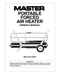
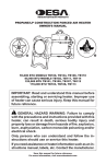
R
HIGH PRESSURE
PORTABLE
FORCED
AIR HEATER
OWNER’S MANUAL
350 SIDE
PFA/PV 008
Model B350CE
Heater Size: 340,000 Btu/Hr
IMPORTANT
Read and understand this manual before assembling, starting, or servicing
heater. Improper use of heater can cause serious injury. Keep this manual
for future reference.
95
CONTENTS
SECTION
PAGE
Safety Information .................................................................................... 2
Product Identification ............................................................................... 4
Unpacking ................................................................................................. 4
Assembly .................................................................................................. 4
Theory of Operation ................................................................................. 6
Fuels ......................................................................................................... 7
Ventilation ................................................................................................ 7
Operation .................................................................................................. 8
Storing, Transporting, or Shipping ........................................................... 9
Preventative Maintenance Schedule ....................................................... 10
Troubleshooting ...................................................................................... 11
Service Procedures ................................................................................. 14
Upper Shell Removal ..................................................................... 14
Fan Blades...................................................................................... 14
Spark Plug ...................................................................................... 15
Nozzle ............................................................................................ 15
Pump Pressure Adjustment ............................................................ 16
Pump .............................................................................................. 16
Fuel Lines ...................................................................................... 16
Fuel Filters ..................................................................................... 17
Specifications .......................................................................................... 18
Wiring Diagram ...................................................................................... 18
Accessory ............................................................................................... 18
Illustrated Parts Breakdowns and Parts Lists ......................................... 19
EC Conformity Declraration .................................................................. 22
Warranty and Repair Service ................................................... Back Cover
SAFETY
INFORMATION
WARNINGS
IMPORTANT: Read this Owner’s Manual carefully and completely
before trying to assemble, operate, or service this heater. Improper
use of this heater can cause serious injury or death from burns, fire,
explosion, electrical shock, electrocution, and carbon monoxide
poisoning.
DANGER
Carbon monoxide poisoning may lead to death!
Carbon Monoxide Poisoning: Early signs of carbon monoxide poisoning
resemble the flu, with headaches, dizziness, or nausea. If you have these signs,
the heater may not be working properly. Get fresh air at once! Have heater
serviced. Some people are more affected by carbon monoxide than others.
These include pregnant women, people with heart or lung disease or anemia,
those under the influence of alcohol, and those at high altitudes.
2
Safety Information continued on next page
101964
SAFETY
INFORMATION
Continued
WARNINGS Continued
Make certain you read and understand all Warnings. Keep this manual for
reference. It is your guide to safe and proper operation of this heater.
• Use only kerosene or No. 1 fuel oil to avoid risk of fire or explosion. Never use
gasoline, naphtha, paint thinners, alcohol, or other highly flammable fuels.
• Fueling
a) Personnel involved with fueling shall be qualified and thoroughly familiar
with the manufacturer’s instructions and applicable federal, state, and local
regulations regarding the safe fueling of heating units.
b) Only the type of fuel specified on the heater’s data plate shall be used.
c) All flame, including the pilot light, if any, shall be extinguished and the heater
allowed to cool, prior to fueling.
d) During fueling, all fuel lines and fuel-line connections shall be inspected for
leaks. Any leaks shall be repaired prior to returning the heater to service.
e) At no time shall more than one day’s supply of heater fuel be stored inside a
building in the vicinity of the heater. Bulk fuel storage shall be outside the
structure.
f) All fuel storage shall be located a minimum of 25 feet (762 cm) from heaters,
torches, welding equipment, and similar sources of ignition (exception: the fuel
reservoir integral with the heater unit).
g) Whenever possible, fuel storage shall be confined to areas where floor
penetrations do not permit fuel to drip onto or be ignited by a fire at lower
elevation.
h) Fuel storage shall be in accordance with the authority having jurisdiction.
• Never use heater where gasoline, paint thinner, or other highly flammable vapors
are present.
• Follow all local ordinances and codes when using heater.
• Use only in well vented areas. Provide at least three square feet (2800 square cm)
of fresh, outside air for each 100,000 Btu/Hr of rating.
• Use only in places free of flammable vapors or high dust content.
• Use only with the electrical voltage and frequency specified on model plate.
• Use only a three-prong, grounded (earthed) extension cord.
• Heaters used in the vicinity of tarpaulins, canvas, or similar enclosure materials
shall be located a safe distance from such materials. The recommended minimum safe distance is 10 feet (304.8 cm). It is further recommended that these
enclosure materials be of a fire retardant nature. These enclosure materials shall
be securely fastened to prevent them from igniting or from upsetting the heater
due to wind action.
• Minimum heater clearances from combustibles:
Outlet: 8 Ft. (250 cm)
Top, Rear, and Sides: 4 Ft. (125 cm)
• Locate heater on a stable and level surface while hot or running or a fire may
occur.
• When heater is moved or stored, it must be in a level position or fuel spillage may
occur.
• Keep children and animals away from heater.
• Unplug heater when not in use.
• This heater has a built-in thermostat. Plugged-in heater may start at anytime.
• Never use heater in living or sleeping areas.
• Never block air inlet (rear) or air outlet (front) of heater.
• Never move, handle, refuel, or service a hot, operating, or plugged in heater.
• Never attach duct work to front or rear of heater.
3
101964
PRODUCT
IDENTIFICATION
Hot Air Outlet
Upper Shell
;;
;;
Lower Shell
Fuel Cap
Thermostat
Flame-out Control
Reset Button
Motor and
Pump
Assembly
Power Cord
Fuel Tank
Figure 1 - B350CE Btu/Hr Model
UNPACKING
1. Remove all protective packing applied to heater for shipment.
2. Remove heater from shipping container.
3. Check heater for any shipping damage. If heater is damaged, promptly inform
dealer where you bought heater.
ASSEMBLY
This model is furnished with wheels and front and rear handles. Wheels, handles,
and mounting hardware are found in the shipping carton.
TOOLS NEEDED
•
•
Pliers
Two - 7/16" Open or Adjustable Wrenches
1. Slide axle through wheel support frame. Install wheel spacer and then one flat
washer on each end of axle.
2. Install wheels on axle.
IMPORTANT: When installing wheels, point exetended hub of wheels toward
wheel support frame (see Figure 2, page 5).
3. Slide one flat washer on each axle end in front of wheel.
4. Install cotter pins through holes at each end of axle. Bend cotter pins with pliers
to secure.
5. Place heater on wheel support frame. Make sure air inlet end (rear) of heater is
over wheels. Line up holes on fuel tank flange with holes on wheel support
frame.
6. Place front and rear handles on top of fuel tank flange. Insert screws through
handles, fuel tank flange, and wheel support frame. Attach nut finger tight after
inserting each screw.
7. After inserting all screws, tighten nuts firmly.
4
101964
ASSEMBLY
Continued
Front Handle
Hot Air
Outlet
Rear
Handle
Screw
Fuel Tank
Flange
;;
;;
;;
Wheel
Support
Frame
Air Inlet
Extended
Hub
Nut
Wheel
Axle
Cotter
Pin
Wheel Spacer
Flat Washer
Flat Washer
Figure 2 - Wheel and Handle Assembly
5
101964
THEORY OF
OPERATION
The Fuel System: The motor turns the fuel pump. The fuel pump pulls fuel from
the fuel tank. The fuel pump pushes fuel through a filter and a solenoid valve and out
the burner head nozzle. A fine mist of fuel is sprayed into the combustion chamber.
The Air System: The motor turns the fan. The fan pushes air into and around the
combustion chamber. This air is heated and provides a stream of clean, hot air.
The Ignition System: The electronic ignitor sends voltage to the spark plug. The
spark plug ignites the fuel and air mixture.
The Flame-out Control System: This system causes the heater to shut down if
the flame goes out. It also allows the fan to continue running after normal shutdown
of heater. This cools the combustion chamber.
Spark
Plug
Combustion
Chamber
Solenoid
Burner
Fan
Valve
Head
Clean
Heated
Air Out
Motor
Fuel Pump/
Fuel Filter
Cool
Air In
Fuel
Pickup
Line
Fuel Tank
Nozzle
Fuel Line To
Solenoid Valve
Air for Combustion
and Heating
Electronic
Ignitor
Fuel
Filter
Fuel
Figure 3 - Cross Section Operational View
6
101964
FUELS
WARNING
Use only kerosene or No. 1 fuel oil to avoid risk of fire or
explosion. Never use gasoline, naphtha, paint thinners, alcohol,
or other highly flammable fuels.
Do not use heavy fuels such as No. 2 fuel oil or No. 2 diesel. Using heavy fuels
will result in:
• clogged fuel filter and nozzle
• carbon build-up on spark plug
• the need of non-toxic anti-icer in fuel during very cold weather
IMPORTANT: Use a KEROSENE ONLY storage container. Be sure storage
container is clean. Foreign matter such as rust, dirt, or water will cause flame-out
control to shut down heater. Foreign matter may also require fuel system to be
cleaned frequently.
VENTILATION
WARNING
Follow the minimum fresh, outside air ventilation requirements.
If proper fresh, outside air ventilation is not provided, carbon
monoxide poisoning can occur. Provide proper fresh, outside air
ventilation before running heater.
Fresh Air Opening Requirements
Heater Size
340,000 Btu/Hr
Square
Feet Opening
10.5
Square
Centimeter Opening
9755
Note: If you use more than one heater, provide extra fresh air. Provide a fresh air
opening of at least three square feet (2800 square cm) for each 100,000 Btu/Hr
rating.
7
101964
OPERATION
WARNING
Review and understand the warnings in the Safety Information
Section. They are needed to safely operate this heater.
To Start Heater
1. Follow all ventilation and safety information.
2. Fill fuel tank with kerosene or No. 1 fuel oil.
3. Attach fuel cap.
4. Set thermostat dial to desired temperature. Note: Thermostat setting must be
higher than surrounding air temperature.
5. Plug power cord of heater into a standard 220/240 volt, 50 hertz, grounded
(earthed) outlet. Use an extension cord if needed. Use only a three-wire,
grounded (earthed) extension cord.
Extension Cord Wire Size Requirements
Up to 100 feet (30.5 meters) long, use 16 AWG (1.0 mm2) conductor
101 to 200 feet (30.6 to 61 meters) long, use 14 AWG (1.5 mm2) conductor
201 to 300 feet (61.1 to 91.5 meters) long, use 12 AWG (2 mm2) conductor
6. The motor will start when power cord is plugged into outlet. The heater should
ignite at once. If heater does not ignite, restart heater. To restart heater, wait
60 seconds, then push in flame-out control reset button. Flame-out control
reset button is at rear of heater near power cord (see Figure 4).
Note: If starting heater for first time, you may need to restart heater several times
before heater ignites. You may also have to do this after taking heater out of
storage.
;;;
;;;
;;;
Flame-out
Control Reset
Button
Figure 4 - Flame-out Control Reset Button
8
101964
OPERATION
To Stop Heater
Continued
CAUTION
Never unplug heater while heater is running. Heater must go
through purge cycle. The purge cycle cools the combustion
chamber. Damage to heater can occur if combustion chamber is
not cooled. Do not restart heater until purge cycle is complete.
1. Turn thermostat dial to lowest temperature setting. This will cause heater
flame to go out. The motor will continue to run during the purge cycle. This
allows the fan to cool the combustion chamber. When the purge cycle is
finished, the motor will stop. Do not unplug heater until purge cycle is
finished.
2. Unplug extension cord from outlet.
3. To temporarily stop heater, set thermostat at a temperature lower than air
around heater. Heater will cycle back on if air temperature around heater
matches thermostat setting.
To Restart Heater
CAUTION
Do not restart heater until purge cycle is finished. The purge
cycle cools the combustion chamber.
1. Wait until purge cycle is finished after stopping heater.
2. Repeat steps under To Start Heater, page 8.
STORING,
TRANSPORTING,
OR SHIPPING
Note: If shipping, transport companies require fuel tanks to be empty.
1. Drain all fuel from fuel filters, fuel lines, and pump (see Fuel Filters [Tank Fuel
Filter], page 17).
2. Clean and flush fuel filter and canister attached to fuel pump (see Fuel Filters
[Pump Fuel Filter], page 17).
3. Remove drain plug and drain fuel tank.
4. Replace drain plug.
5. Add one gallon (four liters) of clean kerosene to fuel tank.
6. Attach fuel cap.
7. Move the heater forwards and backwards to stir fuel.
8. Remove drain plug and drain fuel tank.
9. Replace drain plug.
10. Add two gallons (eight liters) of clean kerosene or No. 1 fuel oil to fuel tank.
11. Replace fuel cap.
12. Operate heater for 5 minutes (see Operation, page 8).
13. Stop heater and let cool completely.
14. Remove drain plug and drain fuel tank.
15. Replace drain plug.
16. Properly dispose of old and dirty fuel.
17. Store heater in a dry location. Make sure storage place is free of dust and
corrosive fumes.
IMPORTANT: Do not store kerosene over summer months for use during next
heating season. Using old fuel could damage heater.
9
101964
PREVENTATIVE
MAINTENANCE
SCHEDULE
WARNING
Never service heater while it is plugged in, operating, or hot.
Severe burns and electrical shock can occur.
Item
How Often
How To
Fuel tank
Flush every 150-200 hours
of operation or as needed.
See Storage, page 9.
Filler neck screen
Check for trash when
filling fuel tank. Clean
when dirty.
Lift out of fuel tank and rinse
with clean kerosene.
Fuel filter assembly
(Fuel tank)
Clean twice a heating
season or replace as
needed.
See Fuel Filters, page 17.
Fuel filter lines
Check and tighten loose
connections occasionally.
See Fuel Lines, Page 16.
Fuel filter (Pump)
Clean fuel filter element
every 250 hours.
See Fuel Filters, page 17.
Spark plug
Clean and regap every 300
hours of operation or
replace as needed.
See Spark Plug, page 15.
Fan blades
Clean each season or as
needed.
See Fan Blades, page 14.
Air passages around
burner head
Check each season for dirt
and trash.
Remove dirt and trash with
clean, soft cloth.
Motor
Not required, permanently
lubricated.
10
101964
TROUBLESHOOTING
WARNING
Never service heater while it is plugged in, operating, or hot.
Severe burns and electrical shock can occur. Only a qualified
service person should service and repair heater.
OBSERVED
PROBLEM
Motor does not
start when heater
is plugged in and
thermostat setting
is higher than
surrounding air
temperature.
POSSIBLE CAUSE
REMEDY
1. No power or low voltage
at heater due to:
A) Damaged power cord
or extension cord
B) Wrong size extension
cord
C) Heater plugged into
outlet with voltage lower
than 220/240 volts
1. A) Check condition of
power cord or extension
cord. Repair or replace if
damaged.
B) Use extension cord with
proper wire size (see To
Start Heater, page 8).
C) Make sure heater is
plugged into 220/240 volt,
50 hertz outlet.
2. Loose electrical connections
2. Check connections.
Tighten if loose.
3. Motor overload protector
tripped due to:
A) Dirty fan
B) Debris pulled into fan
area by fan
C) Binding pump
D) Low voltage
3. A) See Fan Blades, page 14.
B) Remove debris from fan
and fan guard area.
C) Turn fan by hand. If fan
is hard to turn, see Pump,
page 16.
D) See steps B and C under
item 1 above.
Note: Be sure to reset
motor overload protector
by pressing reset button on
top of motor.
4. Flame-out control not reset 4. Press and release flame-out
control reset button. See
Figure 4, page 8 for button
location.
5. Damaged flame-out
control
5. Replace flame-out control.
6. Damaged power relay
6. Replace power relay.
7. Damaged thermostat
7. Replace thermostat.
8. Binding pump
8. Turn fan by hand. If fan is
hard to turn, see Pump, page
16.
11
101964
TROUBLESHOOTING
Continued
OBSERVED
PROBLEM
Heater will not
ignite, but motor
runs for a short
period of time.
POSSIBLE CAUSE
REMEDY
1. A) Fuel tank empty
B) Water in fuel
C) Wrong fuel
1. A) Add fuel to tank.
B) Check fuel tank for
bubbles of water in bottom.
If found, remove fuel (see
Storage, page 9). Clean tank
and fuel filters (see Fuel
Filters, page 17). Fill with
clean fuel.
C) Remove wrong fuel (see
Storage, page 9). Clean tank
and fuel filters (see Fuel
Filters, page 17). Fill with
correct fuel.
2. Dirt in nozzle
2. Replace nozzle (see Nozzle,
page 15).
3. Very low temperature
may cause fuel to thicken
and not flow
3. Move heater to warmer place
until fuel flows freely.
4. Dirty fuel filters
4. Clean fuel filters (see Fuel
Filters, page 17).
5. Wrong pump pressure
5. Adjust pump pressure (see
Pump Pressure Adjustment,
page 16).
6. Spark plug wire disconnected from plug
6. Connect spark plug wire to
spark plug.
7. Spark plug problems due 7. A) Adjust electrode gap to
.055" (1.4 mm) (see Spark
to:
Plug, page 15).
A) Wrong gap
B) Clean fuel from spark
B) Plug wet with fuel
plug with clean, soft cloth.
C) Carbon deposits on
C) Replace plug if heavily
plug
coated with carbon (see
D) Damaged plug
Spark Plug, page 15).
D) Inspect plug for worn or
eroded electrodes. If found,
replace plug (see Spark Plug,
page 15).
8. Solenoid valve not
opening
8. Check electrical connections
and voltage to solenoid. If
good, replace solenoid valve.
WARNING
High Voltage!
9. Damaged electronic ignitor 9. Replace electronic ignitor.
12
101964
TROUBLESHOOTING
Continued
OBSERVED
PROBLEM
POSSIBLE CAUSE
Heater ignites, but 1. Wrong pump pressure
flame-out control
shuts off heater
after a short period
2. Dirty fuel filters
of time.
Heater burns, but
puffs of smoke can
be seen.
Heater does not
burn steady.
Heater burns with
odor.
Heater smokes
continuously.
REMEDY
1. Adjust pump pressure (see
Pump Pressure Adjustment,
page 16).
2. Clean fuel filters (see Fuel
Filters, page 17).
3. Dirt in nozzle
3. Replace nozzle (see Nozzle,
page 15).
4. Dirty photocell lens
4. Clean photocell lens with
clean, soft cloth.
5. Open or damaged
photocell
5. Replace photocell.
6. Bad flame-out control
6. Replace flame-out control.
7. Damaged fan switch
7. Replace fan switch.
1. Wrong pump pressure
1. Adjust pump pressure ( see
Pump Pressure Adjustment,
page 16).
2. A) Heater almost out of
fuel
B) Water condensation
in fuel tank
C) Wrong fuel
2. A) Add fuel to tank.
B) Check fuel tank for
bubbles of water in bottom. If
found, remove fuel (see
Storage, page 9). Clean tank
and fuel filters (see Fuel
Filters, page 17). Fill with
clean fuel.
C) Remove wrong fuel (see
Storage, page 9). Clean tank
and fuel filters (see Fuel
Filters, page 17). Fill with
correct fuel.
3. Dirty fuel filters
3. Clean fuel filters (see Fuel
Filters, page 17).
4. Air leak in suction
system
4. Tighten all fuel line connections (see Fuel Lines, page
16).
5. Dirty nozzle
5. Replace nozzle (see Nozzle,
page 15).
6. Low voltage causing
motor to operate below
rated speed
6. Check voltage at heater.
Voltage at heater should
never be less than 198 volts.
7. Loose fuel line
7. Check and tighten all fuel line
connections (see Fuel Lines,
page 16).
13
101964
SERVICE
PROCEDURES
WARNING
Never service heater while it is plugged in, operating, or hot.
Severe burns and electrical shock can occur. Only a qualified
service person should service and repair heater.
Upper Shell Removal
1. Remove screws and
lockwashers along each side
and top of heater using 5/16"
nut-driver. These screws
attach upper and lower shells
together (see Figure 5).
2. Lift upper shell off.
Upper Shell
;;
;;
Figure 5 - Upper Shell Removal
Fan Blades
1. Remove upper shell (see
above).
2. Clean fan blades with clean,
soft cloth moistened with
kerosene or solvent (see
Figure 6).
3. Dry fan blades thoroughly.
4. Replace upper shell.
Fan Blade
Figure 6 - Fan Blades
14
101964
Spark Plug
1. Remove upper shell (see page
14).
2. Remove spark plug wire from
spark plug (see Figure 7).
3. Remove spark plug from
burner head using 13/16" openend wrench (see Figure 7).
4. Replace spark plug if damaged
or heavily coated with carbon.
5. Clean and regap spark plug
electrodes to .055 inch
(1.4 mm) (see Figure 8).
6. Install spark plug in burner
head.
7. Attach spark plug wire to spark
plug.
8. Replace upper shell.
Burner
Head
Spark Plug
Spark
Plug Wire
Figure 7 - Spark Plug Removal
.055 inch (1.4 mm)
Nozzle
1. Remove upper shell (see page
14).
2. Remove fuel line from
solenoid valve using 7/16"
wrench.
3. Remove spark plug wire from
spark plug.
4. Remove spark plug from
burner head using 13/16"
open-end wrench.
5. Remove five screws using
5/16" nut-driver and remove
burner head from combustion
chamber.
6. Place burner head into vise
and lightly tighten.
7. Carefully remove nozzle from
burner head using 5/8" socket
wrench (see Figure 9).
8. Inspect nozzle for damage. If
damaged or clogged, replace
nozzle.
9. Make sure plug is in place on
burner head.
10.Replace nozzle into burner
head and tighten to 80-110
inch-pounds (9.1 to 12.4 n-m).
11.Attach burner head to combustion chamber.
12.Install spark plug in burner
head.
13.Attach spark plug wire to
spark plug.
14.Attach fuel line to solenoid
valve. Tighten firmly.
15.Replace upper shell.
Figure 8 - Spark Plug Gap
Nozzle
Spark Plug
Plug
Burner
Head
Solenoid
Valve
Spark
Plug
Wire
Fuel Line
Figure 9 - Replacing Nozzle
15
101964
Pump Pressure
Adjustment
Pressure
Gage
Fuel Pump Port
Marked “PRESS ADJ”
i
ps
1. Remove pressure gage plug
from fuel pump port marked
“GAGE.”
2. Install accessory pressure
gage (part number M4574) to
fuel pump port marked
“GAGE” (see Figure 10).
3. Start heater (see Operation,
page 8). Allow motor to
reach full speed.
4. Adjust pressure to 100 psi.
Use small flat blade screwdriver to turn slotted screw at
fuel pump port marked
“PRESS ADJ.” Turn screw
clockwise to increase
pressure. Turn screw
counterclockwise to decrease
pressure.
5. Remove pressure gage.
Replace pressure gage plug
in fuel pump port marked
“GAGE.”
Fuel Pump Port
Marked “GAGE”
Figure 10 - Adjusting Pump Pressure
Hex Screw On
Flange Clamp
Pump
(Procedure if pump is binding)
1. Remove upper shell (see page
14).
2. Loosen hex screw on flange
clamp at rear of motor with
5/16" nut-driver (see Figure
11).
3. Turn fan with hand (see Figure
12).
4. If fan turns freely, tighten
screw on flange clamp.
5. If fan does not turn freely,
replace pump.
6. Replace upper shell.
Figure 11 - Location of Screw
on Flange Clamp
Burner Head
Fuel Lines
(Procedure for tightening
fuel lines)
1. Remove upper shell (see page
14).
2. Use 7/16" wrench and tighten
fuel lines at solenoid valve (see
Figure 13), pump, and pump
fuel filter assembly (see Figure
14).
Figure 12 - Turning Fan with Hand
;;;
;;;
;;;
Pump
Fuel Filter
Assembly
Pump
Solenoid
Valve
Figure 13 - Fuel Line at
Solenoid Valve
Fuel
Line
Fuel
Lines
Figure 14 - Fuel Lines at Pump and
Pump Fuel Filter Assembly
16
101964
Fuel Filters
A. Tank Fuel Filter
1. Disconnect fuel lines from
pump and pump fuel filter
assembly with 7/16" wrench
(see Figure 15).
2. Carefully pry fuel filter loose
from fuel tank with flat end of
screwdriver.
3. Inspect fuel filter for water or
dirt.
4. Rinse fuel filter and fuel lines
with clean kerosene.
5. Replace fuel filter into fuel
tank.
6. Connect fuel lines to pump
and pump fuel filter assembly.
;;;
;;;
;;;
Pump Fuel
Filter
Assembly
Pump
Fuel Lines
Fuel Filter
Figure 15 - Removing Tank Fuel Filter
B. Pump Fuel Filter
1. Unscrew canister bottom
from canister top with
Channellock pliers.
2. Remove fuel filter and gasket
from canister bottom (see
Figure 16).
3. Inspect canister bottom and
fuel filter for water or dirt.
4. Rinse canister bottom in
clean kerosene.
5. Wipe inside of canister
bottom dry with clean cloth.
6. Rinse fuel filter in clean
kerosene.
7. Put clean fuel filter and
gasket back in canister
bottom.
8. Screw canister bottom into
canister top.
Canister Top
Gasket
Fuel Filter
Canister Bottom
Figure 16 - Fuel Pump Filter and Canister
17
101964
SPECIFICATIONS
Output Rating (Btu/Hr)
Fuel
Fuel Tank Capacity (U.S. Gal./Liters)
Fuel Consumption
(Gal. Per Hr/Liter Per Hr)
Electric Requirements
Amperage (Normal Run)
Motor RPM
Fuel Pump Pressure (PSI)
Spark Plug Gap
Weight (approx. lbs./kilograms) Dry (net)
With Full Fuel Tank
340,000
Use Only Kerosene or No. 1 Fuel Oil
30/113.6
2.5/9.5
220/240V, 50 Hz
5
2850
100
.055" (1.4 mm)
180/82
390/177
Green/Yellow
WIRING
DIAGRAM
Black
7
5
B
A
Black
Thermostat
B Flame-out
Control R
White
Start Capacitor
Black
Red
Relay
Motor
White
White
Black
Blue
Orange
Yellow
Red
Purple
Black
Terminal
Board
Terminal
Board
Red
Reset
Button
White
White
Black
1
Yellow
White
2
White
Fan
Switch
Purple
Spark
Plug
3
Yellow
Solenoid
Valve
Ignitor
Plug
Brown
Green/Yellow
White
Blue
Orange
Blue
Photocell
220/240V~
50HZ
ACCESSORY
Purchase this heater accessory from you local dealer.
HIGH PRESSURE AIR GAGE - M4574
Special tool to check pump pressure
18
101964
PARTS LIST
Burner Head Assembly
REF
NO.
PART NO.
DESCRIPTION
1
2
3
4
5
6
7
8
9
10
M10908-2
099229-01
HA3012
M51070-02
M51170-01
M50924-02
69246
M50077-02
M50297
M50429
Screw, #6-32 x 3/8"
Photocell bracket
Spark plug
Nozzle
Plug
Burner head body
Straight nipple
Solenoid valve
Compression elbow
Spark plug gasket
3
QTY.
10
4
2
1
1
1
1
1
1
1
1
1
5
1
6
2
7
8
9
Motor and Pump Assembly
REF.
NO.
PART NO.
1
2
3
4
5
6
097495-02AA
HF5-5C
WLIE-5
M11084-26
M50064-07
M50116
7
8
9
10
11
12
13
14
15
16
17
18
19
20
21
22
23
24
25
26
27
28
29
30
31
32
33
DESCRIPTION
Wiring cover
Screw, 5/16-24 x 5/16"
Lockwasher, 5/16"
Screw, #10-16 x 3/8"
Motor
Flange clamp
(holds pump to motor)
099520-04AA Motor support
57413
Street elbow
M17499-2
Pipe nipple
098102-01
Fuel filter assembly
098103-01
Filter element
(inside fuel filter
assembly, includes
rubber gaskets)
M50114-02
90˚ Male elbow
M50297
Compression elbow
M50113-02
Straight fitting
M50065-02
Fuel pump
WLIE-5
Lockwasher, 5/16"
NPF-5C
Hex nut, 5/16-24"
097630-02
Flame-out control
098894-01
Power relay
M50104-02
Shorty bushing
M10908-2
Screw, #6-32 x 3/8"
M50400
Strain relief bushing
RF3-5B
Screw, #10-32 x 1/2"
099125-05
Terminal board
099125-04
Terminal board
099157-01
Rivet
M12650-12
Capacitor
M51226-01
Capacitor cap
M51231-01
Capacitor bracket
FPF3-4C
Screw, #10-32 x 1/2"
WLE-3
Lockwasher, #10
NPF-3C
Nut, #10-32
NPF-3B
Nut, #10-32
099177-01
Hex nut
1
QTY.
30
1
4
4
3
1
4
2
3
1
1
2
1
1
5
11
10
9
6
8
14
1
1
1
1
1
4
4
1
1
3
2
1
1
1
1
2
1
1
1
2
7
2
2
1
12
13
27
8
26
29
28
20
19
18
21
32
30
32
30
17
30
24
23
25
7
33
31
15
16
22
19
101964
ILLUSTRATED
PARTS
BREAKDOWN
2
42
1
2
42
3
2
6
7
19
8
10
20
4
42
21
13
22
12
11
14
43
42
16
25
23
26
30
28
27
17
18
24
20
9
15
13
31
;;
;;
;;
29
32
42
2
41
34
33
34
39
35
5
2
36
38
37
40
37
20
101964
PARTS LIST
This list contains replaceable parts used in your heater. When ordering parts, be
sure to provide the correct model and serial numbers (from the model plate), then
the part number and description of the desired part.
REF.
NO.
PART NO.
DESCRIPTION
1
2
3
4
5
6
7
8
9
10
11
12
13
14
15
16
17
18
19
20
21
22
23
24
25
26
27
28
29
30
31
32
33
34
35
36
37
38
39
40
41
42
43
M50060-02AB
M11084-27
M50542-01
M30865-02
1000576
†
M16656-18
M50121-02
102243-01AA
M51336-02
M51160-01
M50278
M11084-26
†
079673-03
M50295
M50050
098641-07
M50061-02AB
M11271-8
M11084-3
M50104-02
099509-03
M50115-01
M50062-03
097702-01
HA2210
HC4-18C
M51043-01
M50062
098513-05
M50063
M18774
NTC-4C
M50389
C5-10C
WP-10C
M50296
M27417
099566-03
M11084-29
WLE-3
M50104-03
Upper shell
Screw, #10-16 x 1/2"
Combustion chamber & shield
Bushing
Grommett
Burner head assembly
Photocell assembly
Fan
Fan guard
Fan switch
Fan switch cover
Sleeve
Screw, #10-16 x 3/8"
Motor & pump assembly
Power cord
Fuel line
Ignition boot
Electronic ignitor
Lower shell
Clip nut
Screw, #12-14 x 1/2"
Bushing
Wire harness
Fuel line assembly
Front handle
Fuel cap
Filler neck screen
Screw, 1/4-20 x 2 1/4"
Screw, 1/4-20 x 1 1/2"
Rear handle
Fuel tank
Wheel support frame
Axle
Hex lock nut, 1/4-20
Wheel
Cotter pin, 5/32 x 1 1/4"
Flatwasher, 5/8"
Wheel spacer
Drain plug
Thermostat
Screw, #10-16 x 3/4"
Lockwasher, #10
Bushing
QTY.
1
25
1
3
1
1
1
1
1
1
1
1
13
1
1
1
1
1
1
14
4
2
1
1
1
1
1
6
2
1
1
1
1
8
2
2
4
2
1
1
2
29
1
† Not available as complete assembly. See page 19.
21
101964
EC
CONFORMITY
DECLARATION
EC CONFORMITY DECLARATION
DESA Europe B.V.
Innsbruckweg 144, NL-3047 AH
Postbus 11158
NL-3004 ED Rotterdam
Holland
Manufacturer:
DESA International, Inc.
2701 Industrial Drive
Bowling Green, KY 42101 U.S.A.
Kerosene Portable Forced Air Heater
Model Number: B350CE
It is declared that these models conform to the Machinery Directive 89/392/EEC,
93/68/EEC including 91/368/EEC.
We declare that the models noted are in conformity.
Company
DESA International, Inc.
______________________________________________________
Name
Douglas D. Rohrer
______________________________________________________
Title
Vice President, Specialty Products Engineering
______________________________________________________
07/04/95 — Bowling Green, KY
_____________________________
Date and Place
_______________________
Signature
22
101964
NOTES
_______________________________________________________________
_______________________________________________________________
_______________________________________________________________
_______________________________________________________________
_______________________________________________________________
_______________________________________________________________
_______________________________________________________________
_______________________________________________________________
_______________________________________________________________
_______________________________________________________________
_______________________________________________________________
_______________________________________________________________
_______________________________________________________________
_______________________________________________________________
_______________________________________________________________
_______________________________________________________________
_______________________________________________________________
_______________________________________________________________
_______________________________________________________________
_______________________________________________________________
_______________________________________________________________
_______________________________________________________________
_______________________________________________________________
_______________________________________________________________
_______________________________________________________________
_______________________________________________________________
_______________________________________________________________
_______________________________________________________________
_______________________________________________________________
_______________________________________________________________
_______________________________________________________________
_______________________________________________________________
_______________________________________________________________
_______________________________________________________________
_______________________________________________________________
_______________________________________________________________
_______________________________________________________________
_______________________________________________________________
____________________________________________________________
101964
23
WARRANTY AND REPAIR SERVICE
CERTIFICATE OF GENERAL
EQUIPMENT - LIMITED 90 DAY WARRANTY
DESA International warrants new Products sold by it to be
free from defects in material or workmanship for a period of
ninety days after date of delivery to the first user and subject to
the following conditions:
DESA International's obligation and liability under this
Warranty is expressly limited to repairing or replacing at DESA
International's option, any parts which appear to DESA International upon inspection to have been defective in material or
workmanship when shipped from the factory. Such parts shall
be provided at no cost to the user, at the business establishment
of any factory authorized service center or the factory during
regular working hours. The Warranty shall not apply to component parts or accessories of Products not manufactured by
DESA International and which carry the warranty of the manufacturer thereof, or to normal maintenance (such as pressure
adjustments) or to normal maintenance parts (such as filters
and spark plugs). Replacement or repair parts installed in the
Product covered by this Warranty are warranted only for the
remainder of this Warranty as if such parts were original components of said Product. DESA INTERNATIONAL MAKES NO
OTHER EXPRESS WARRANTY. TO THE EXTENT PERMITTED BY LAW DESA INTERNATIONAL MAKES NO IMPLIED
WARRANTY AND MAKES NO WARRANTY OF MERCHANTABILITY OR FITNESS FOR ANY PARTICULAR PUR-
POSE. IN ANY EVENT IMPLIED WARRANTIES INCLUDING
THOSE OF MERCHANTABILITY AND FITNESS FOR A PARTICULAR PURPOSE ARE LIMITED TO THE DURATION OF
THIS EXPRESS WARRANTY.
Any transportation charges, costs of installation, duty,
taxes or any other charges whatsoever must be borne by the
user. DESA International's obligation under this limited Warranty shall not include any liability for direct, indirect, incidential,
or consequential damage or delay. If requested by DESA
International, Products or parts for which a warranty claim is
made are to be returned transportation prepaid by user to the
factory. Any improper use, including operation after discovery
of defective or worn parts, operation beyond capacity, substitution of parts not approved by DESA International, or any
alteration or repair by others in such manner as in DESA
International's judgement affects the Product materially and
adversely, shall void this Warranty.
NO EMPLOYEE OR REPRESENTATIVE IS AUTHORIZED
TO CHANGE THIS WARRANTY IN ANY WAY OR GRANT
ANY OTHER WARRANTY UNLESS SUCH CHANGE IS
MADE IN WRITING AND SIGNED BY AN OFFICER OF DESA
INTERNATIONAL AT ITS HOME OFFICE.
WARRANTY SERVICE
Always specify model and serial numbers when communicating
with the factory.
We reserve the right to amend these specifications at any time
without notice. The only Warranty applicable is our standard
written Warranty. We make no other Warranty, expressed or
implied.
A Service Manual is available by writing to the Technical Service
Department at:
Corporate Headquarters
2701 Industrial Drive
P.O. Box 90004
Bowling Green, Kentucky 42102-9004
U.S.A.
Printed in U.S.A.
24
101964-01
Rev. B
9/95
101964