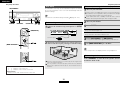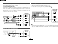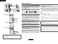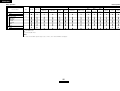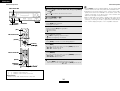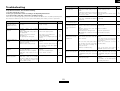
1
AV SURROUND RECEIVER
AVR-1507
OPERATING INSTRUCTIONS
BEDIENUNGSANLEITUNG
MODE D’EMPLOI
ISTRUZIONI PER L’USO
INSTRUCCIONES DE FUNCIONAMIENTO
GEBRUIKSAANWIJZING
BRUKSANVISNING
ENGLISH
DEUTSCH
FRANCAIS
ITALIANO
ESPAÑOL
¢SAFETY PRECAUTIONS
CAUTION
RISK OF ELECTRIC SHOCK
DO NOT OPEN
CAUTION:
TO REDUCE THE RISK OF ELECTRIC SHOCK, DO NOT REMOVE
COVER (OR BACK). NO USER-SERVICEABLE PARTS INSIDE.
REFER SERVICING TO QUALIFIED SERVICE PERSONNEL.
The lightning flash with arrowhead symbol, within an
equilateral triangle, is intended to alert the user to the
presence of uninsulated “dangerous voltage” within the
product’s enclosure that may be of sufficient magnitude to
constitute a risk of electric shock to persons.
The exclamation point within an equilateral triangle is
intended to alert the user to the presence of important
operating and maintenance (servicing) instructions in the
literature accompanying the appliance.
WARNING:
TO REDUCE THE RISK OF FIRE OR ELECTRIC SHOCK, DO NOT
EXPOSE THIS APPLIANCE TO RAIN OR MOISTURE.
NEDERLANDS
SVENSKA
DECLARATION OF CONFORMITY
CAUTION:
We declare under our sole responsibility that this product, to which this
declaration relates, is in conformity with the following standards:
EN60065, EN55013, EN55020, EN61000-3-2 and EN61000-3-3.
Following the provisions of 73/23/EEC, 89/336/EEC and 93/68/EEC Directive.
To completely disconnect this product from the mains, disconnect the plug
from the wall socket outlet.
The mains plug is used to completely interrupt the power supply to the unit
and must be within easy access by the user.
ÜBEREINSTIMMUNGSERKLÄRUNG
VORSICHT:
Wir erklären unter unserer Verantwortung, daß dieses Produkt, auf das sich
diese Erklärung bezieht, den folgenden Standards entspricht:
EN60065, EN55013, EN55020, EN61000-3-2 und EN61000-3-3.
Entspricht den Verordnungen der Direktive 73/23/EEC, 89/336/EEC und
93/68/EEC.
Um dieses Gerät vollständig von der Stromversorgung abzutrennen, trennen
Sie bitte den Netzstecker von der Wandsteckdose ab.
Die Hauptstecker werden verwendet, um die Stromversorgung zum Gerät
völlig zu unterbrechen; er muss für den Benutzer gut und einfach zu erreichen
sein.
DECLARATION DE CONFORMITE
PRECAUTION:
Nous déclarons sous notre seule responsabilité que l’appareil, auquel se
réfère cette déclaration, est conforme aux standards suivants:
EN60065, EN55013, EN55020, EN61000-3-2 et EN61000-3-3.
D’après les dispositions de la Directive 73/23/EEC, 89/336/EEC et 93/68/EEC.
Pour déconnecter complètement ce produit du courant secteur, débranchez
la prise de la prise murale.
La prise secteur est utilisée pour couper complètement l’alimentation de
l’appareil et l’utilisateur doit pouvoir y accéder facilement.
DICHIARAZIONE DI CONFORMITÀ
ATTENZIONE:
Dichiariamo con piena responsabilità che questo prodotto, al quale la nostra
dichiarazione si riferisce, è conforme alle seguenti normative:
EN60065, EN55013, EN55020, EN61000-3-2 e EN61000-3-3.
In conformità con le condizioni delle direttive 73/23/EEC, 89/336/EEC e
93/68/EEC.
QUESTO PRODOTTO E’ CONFORME
AL D.M. 28/08/95 N. 548
Per scollegare definitivamente questo prodotto dalla rete di alimentazione
elettrica, togliere la spina dalla relativa presa.
La spina di rete viene utilizzata per interrompere completamente l’alimentazione
all’unità e deve essere facilmente accessibile all’utente.
DECLARACIÓN DE CONFORMIDAD
Declaramos bajo nuestra exclusiva responsabilidad que este producto al que
hace referencia esta declaración, está conforme con los siguientes estándares:
EN60065, EN55013, EN55020, EN61000-3-2 y EN61000-3-3.
Siguiendo las provisiones de las Directivas 73/23/EEC, 89/336/EEC y 93/68/EEC.
EENVORMIGHEIDSVERKLARING
Wij verklaren uitsluitend op onze verantwoordelijkheid dat dit produkt, waarop
deze verklaring betrekking heeft, in overeenstemming is met de volgende
normen:
EN60065, EN55013, EN55020, EN61000-3-2 en EN61000-3-3.
Volgens de bepalingen van de Richtlijnen 73/23/EEC, 89/336/EEC en 93/68/EEC.
ÖVERENSSTÄMMELSESINTYG
Härmed intygas helt på eget ansvar att denna produkt, vilken detta intyg
avser, uppfyller följande standarder:
EN60065, EN55013, EN55020, EN61000-3-2 och EN61000-3-3.
Enligt stadgarna i direktiv 73/23/EEC, 89/336/EEC och 93/68/EEC.
I
PRECAUCIÓN:
Para desconectar completamente este producto de la alimentación
eléctrica, desconecte el enchufe del enchufe de la pared.
El enchufe de la alimentación se utiliza para interrumpir por completo el
suministro de alimentación a la unidad y debe de encontrarse en un lugar al
que el usuario tenga fácil acceso.
VOORZICHTIGHEID:
Om de voeding van dit product volledig te onderbreken moet de stekker uit
het stopcontact worden getrokken.
De netstekker wordt gebruikt om de stroomtoevoer naar het toestel volledig
te onderbreken en moet voor de gebruiker gemakkelijk bereikbaar zijn.
FÖRSIKTIHETSMÅTT:
Koppla loss stickproppen från eluttaget för att helt skilja produkten från nätet.
Stickproppen används för att helt bryta strömförsörjningen till apparaten,
och den måste vara lättillgänglig för användaren.
SVENSKA
NEDERLANDS
ESPAÑOL
ITALIANO
FRANCAIS
DEUTSCH
ENGLISH
¢NOTE ON USE / HINWEISE ZUM GEBRAUCH / OBSERVATIONS RELATIVES A L’UTILISATION / NOTE SULL’USO / NOTAS SOBRE EL USO /
ALVORENS TE GEBRUIKEN / OBSERVERA
CAUTION:
• The ventilation should not be impeded by covering the ventilation openings with items,
such as newspapers, tablecloths, curtains, etc.
• No naked flame sources, such as lighted candles, should be placed on the apparatus.
• Attention should be drawn to the environmental aspects of battery disposal.
• Do not expose the set to dripping or splashing fluids.
• No objects filled with liquids, such as vases, shall be placed on the apparatus.
ACHTUNG:
• Avoid high temperatures.
Allow for sufficient heat dispersion when installed in a
rack.
• Vermeiden Sie hohe Temperaturen.
Beachten Sie, daß eine ausreichend Luftzirkulation
gewährleistet wird, wenn das Gerät auf ein Regal gestellt
wird.
• Eviter des températures élevées
Tenir compte d’une dispersion de chaleur suffisante lors de
l’installation sur une étagère.
• Evitate di esporre l’unità a temperature alte.
Assicuratevi che ci sia un’adeguata dispersione del calore
quando installate l’unità in un mobile per componenti
audio.
• Evite altas temperaturas.
Permite la suficiente dispersión del calor cuando está
instalado en la consola.
• Vermijd hoge temperaturen.
Zorg voor een degelijk hitteafvoer indien het apparaat op
een rek wordt geplaatst.
• Undvik höga temperaturer.
Se till att det finns möjlighet till god värmeavledning vid
montering i ett rack.
• Handle the power cord carefully.
Hold the plug when unplugging the cord.
• Gehen Sie vorsichtig mit dem Netzkabel um.
Halten Sie das Kabel am Stecker, wenn Sie den Stecker
herausziehen.
• Manipuler le cordon d’alimentation avec précaution.
Tenir la prise lors du débranchement du cordon.
• Manneggiate il filo di alimentazione con cura.
Agite per la spina quando scollegate il cavo dalla presa.
• Maneje el cordón de energía con cuidado.
Sostenga el enchufe cuando desconecte el cordón de
energía.
• Hanteer het netsnoer voorzichtig.
Houd het snoer bij de stekker vast wanneer deze moet
worden aan- of losgekoppeld.
• Hantera nätkabeln varsamt.
Håll i kabeln när den kopplas från el-uttaget.
•
•
•
•
•
•
•
•
•
Keep the apparatus free from moisture, water, and dust.
Halten Sie das Gerät von Feuchtigkeit, Wasser und Staub •
•
fern.
Protéger l’appareil contre l’humidité, l’eau et lapoussière.
Tenete l’unità lontana dall’umidità, dall’acqua e dalla •
•
polvere.
•
Mantenga el equipo libre de humedad, agua y polvo.
Laat geen vochtigheid, water of stof in het apparaat
binnendringen.
Utsätt inte apparaten för fukt, vatten och damm.
Do not let foreign objects into the apparatus.
Keine fremden Gegenstände in das Gerät kommen lassen.
Ne pas laisser des objets étrangers dans l’appareil.
E’ importante che nessun oggetto è inserito all’interno
dell’unità.
No deje objetos extraños dentro del equipo.
Laat geen vreemde voorwerpen in dit apparaat vallen.
Se till att främmande föremål inte tränger in i apparaten.
• Die Belüftung sollte auf keinen Fall durch das Abdecken der Belüftungsöffnungen durch
Gegenstände wie beispielsweise Zeitungen, Tischtücher, Vorhänge o. Ä. behindert werden.
• Auf dem Gerät sollten keinerlei direkten Feuerquellen wie beispielsweise angezündete
Kerzen aufgestellt werden.
• Bitte beachten Sie bei der Entsorgung der Batterien die geltenden Umweltbestimmungen.
• Das Gerät sollte keinerlei Flüssigkeit, also keinem Tropfen oder Spritzen ausgesetzt
werden.
• Auf dem Gerät sollten keinerlei mit Flüssigkeit gefüllten Behälter wie beispielsweise Vasen
aufgestellt werden.
ATTENTION:
• La ventilation ne doit pas être gênée en recouvrant les ouvertures de la ventilation avec des
objets tels que journaux, rideaux, tissus, etc.
• Aucune flamme nue, par exemple une bougie, ne doit être placée sur l’appareil.
• Veillez à respecter l’environnement lorsque vous jetez les piles usagées.
• L’appareil ne doit pas être exposé à l’eau ou à l’humidité.
• Aucun objet contenant du liquide, par exemple un vase, ne doit être placé sur l’appareil.
PRECAUZIONI:
• Unplug the power cord when not using the apparatus for
long periods of time.
• Wenn das Gerät eine längere Zeit nicht verwendet werden
soll, trennen Sie das Netzkabel vom Netzstecker.
• Débrancher le cordon d’alimentation lorsque l’appareil n’est
pas utilisé pendant de longues périodes.
• Disinnestate il filo di alimentazione quando avete
l’intenzione di non usare il filo di alimentazione per un lungo
periodo di tempo.
• Desconecte el cordón de energía cuando no utilice el
equipo por mucho tiempo.
• Neem altijd het netsnoer uit het stopkontakt wanneer het
apparaat gedurende een lange periode niet wordt gebruikt.
• Koppla ur nätkabeln om apparaten inte kommer att
användas i lång tid.
• Do not let insecticides, benzene, and thinner come in
contact with the apparatus.
• Lassen Sie das Gerät nicht mit Insektiziden, Benzin oder
Verdünnungsmitteln in Berührung kommen.
• Ne pas mettre en contact des insecticides, du benzène et
un diluant avec l’appareil.
• Assicuratevvi che l’unità non venga in contatto con
insetticidi, benzolo o solventi.
• No permita el contacto de insecticidas, gasolina y
diluyentes con el equipo.
• Laat geen insektenverdelgende middelen, benzine of
verfverdunner met dit apparaat in kontakt komen.
• Se till att inte insektsmedel på spraybruk, bensen och
thinner kommer i kontakt med apparatens hölje.
• Le aperture di ventilazione non devono essere ostruite coprendole con oggetti, quali
giornali, tovaglie, tende e così via.
• Non posizionare sull'apparecchiatura fiamme libere, come ad esempio le candele accese.
• Prestare attenzione agli aspetti legati alla tutela dell'ambiente quando si smaltisce la
batteria.
• L’apparecchiatura non deve essere esposta a gocciolii o spruzzi.
• Non posizionare sull'apparecchiatura nessun oggetto contenete liquidi, come ad esempio i
vasi.
PRECAUCIÓN:
• La ventilación no debe quedar obstruida por hacerse cubierto las aperturas con objetos
como periódicos, manteles, cortinas, etc.
• No debe colocarse sobre el aparato ninguna fuente inflamable sin protección, como velas
encendidas.
• A la hora de deshacerse de las pilas, respete la normativa para el cuidado del medio
ambiente.
• No se expondrá el aparato al goteo o salpicaduras cuando se utilice.
• No se colocarán sobre el aparato objetos llenos de líquido, como jarros.
WAARSCHUWING:
* (For apparatuses with ventilation holes)
•
•
•
•
•
•
•
Do not obstruct the ventilation holes.
Die Belüftungsöffnungen dürfen nicht verdeckt werden.
Ne pas obstruer les trous d’aération.
Non coprite i fori di ventilazione.
No obstruya los orificios de ventilación.
De ventilatieopeningen mogen niet worden beblokkeerd.
Täpp inte till ventilationsöppningarna.
• Never disassemble or modify the apparatus in any way.
• Versuchen Sie niemals das Gerät auseinander zu nehmen
oder auf jegliche Art zu verändern.
• Ne jamais démonter ou modifier l’appareil d’une manière
ou d’une autre.
• Non smontate mai, nè modificate l’unità in nessun modo.
• Nunca desarme o modifique el equipo de ninguna manera.
• Nooit dit apparaat demonteren of op andere wijze
modifiëren.
• Ta inte isär apparaten och försök inte bygga om den.
II
• De ventilatie mag niet worden belemmerd door de ventilatieopeningen af te dekken met
bijvoorbeeld kranten, een tafelkleed, gordijnen, enz.
• Plaats geen open vlammen, bijvoorbeeld een brandende kaars, op het apparaat.
• Houd u steeds aan de milieuvoorschriften wanneer u gebruikte batterijen wegdoet.
• Stel het apparaat niet bloot aan druppels of spatten.
• Plaats geen voorwerpen gevuld met water, bijvoorbeeld een vaas, op het apparaat.
OBSERVERA:
• Ventilationen bör inte förhindras genom att täcka för ventilationsöppningarna med föremål
såsom tidningar, bordsdukar, gardiner osv.
• Inga blottade brandkällor, såsom tända ljus, bör placeras på apparaten.
• Tänk på miljöaspekterna när du bortskaffar batteri.
• Apparaten får inte utsättas för vätska.
• Inga objekt med vätskor, såsom vaser, får placeras på apparaten.
ENGLISH
DEUTSCH
FRANCAIS
ITALIANO
ESPAÑOL
NEDERLANDS
SVENSKA
A NOTE ABOUT RECYCLING:
This product’s packaging materials are recyclable and can be reused. Please dispose of any
materials in accordance with the local recycling regulations.
When discarding the unit, comply with local rules or regulations.
Batteries should never be thrown away or incinerated but disposed of in accordance with the local
regulations concerning chemical waste.
This product and the accessories packed together constitute the applicable product according to the
WEEE directive except batteries.
HINWEIS ZUM RECYCLING:
Das Verpackungsmaterial dieses Produktes ist für zum Recyceln geeignet und kann wieder verwendet werden. Bitte
entsorgen Sie alle Materialien entsprechend der örtlichen Recycling-Vorschriften.
Beachten Sie bei der Entsorgung des Gerätes die örtlichen Vorschriften und Bestimmungen.
Die Batterien dürfen nicht in den Hausmüll geworfen oder verbrannt werden; bitte geben Sie die Batterien gemäß
örtlichen Bestimmungen an den Sammelstellen oder Sondermüllplätzen ab.
Dieses Produkt zusammen mit den Zubehörteilen ist das geltende Produkt der WEEE-Direktive, davon
ausgenommen sind die Batterien.
UNE REMARQUE CONCERNANT LE RECYCLAGE:
Les matériaux d’emballage de ce produit sont recyclables et peuvent être réutilisés. Veuillez disposer de tout
matériau conformément aux réglements de recylage locaux.
Lorsque vous mettez cet appareil au rebut, respectez les lois ou réglementations locales.
Les piles ne doivent jamais être jetées ou incinérées, mais mises au rebut conformément aux réglements locaux
concernant les déchets chimiques.
Ce produit et les accessoires emballés ensemble sont des produits conformes à la directive DEEE sauf pour les piles.
NOTA RELATIVA AL RICICLAGGIO:
I materiali di imballaggio di questo prodotto sono riutilizzabili e riciclabili. Smaltire i materiali conformemente alle
normative locali sul riciclaggio.
Per smaltire l’unità, osservare la normativa in vigore nel luogo di utilizzo.
Non gettare le batterie, né incenerirle, ma smaltirle conformemente alla normativa locale sui rifiuti chimici.
Questo prodotto e gli accessori inclusi nell’imballaggio sono applicabili alla direttiva RAEE, ad eccezione delle batterie.
ACERCA DEL RECICLAJE:
Los materiales de embalaje de este producto son reciclables y se pueden volver a utilizar. Disponga de estos
materiales siguiendo los reglamentos de reciclaje de su localidad.
Cuando se deshaga de la unidad, cumpla con las reglas o reglamentos locales.
Las pilas nunca deberán tirarse ni incinerarse. Deberá disponer de ellas siguiendo los reglamentos de su localidad
relacionados con los desperdicios químicos.
Este producto junto con los accesorios empaquetados es el producto aplicable a la directiva RAEE excepto pilas.
EEN AANTEKENING WAT BETREFT HET RECYCLEREN:
Het inpakmateriaal van dit product is recycleerbaar en kan opnieuw gebruikt worden. Er wordt verzocht om zich van
elk afvalmateriaal te ontdoen volgens de plaatselijke voorschriften.
Volg voor het wegdoen van de speler de voorschriften voor de verwijdering van wit- en bruingoed op.
Batterijen mogen nooit worden weggegooid of verbrand, maar moeten volgens de plaatselijke voorschriften
betreffende chemisch afval worden verwijderd.
Op dit product en de meegeleverde accessoires, m.u.v. de batterijen is de richtlijn voor afgedankte elektrische en
elektronische apparaten (WEEE) van toepassing.
EN KOMMENTAR OM ÅTERVINNING:
Produktens emballage är återvinningsbart och kan återanvändas. Kassera det enligt lokala återvinningsbestämmelser.
När du kasserar enheten ska du göra det i överensstämmelse med lokala regler och bestämmelser.
Batterier får absolut inte kastas i soporna eller brännas. Kassera dem enligt lokala bestämmelser för kemiskt avfall.
Denna apparat och de tillbehör som levereras med den är de som uppfyller gällande WEEE-direktiv, med undantag
av batterierna.
III
ENGLISH
Thank you for choosing the DENON AVR-1507 AV Surround Receiver. This remarkable component has been engineered to provide superb surround sound listening with home theater sources such as DVD, as well
as providing outstanding high fidelity reproduction of your favorite music sources.
As this product is provided with an immense array of features, we recommend that before you begin hookup and operation that you review the contents of this manual before proceeding.
Contents
Getting Started
Accessories······················································································2
Before using ····················································································2
Cautions on installation ·································································3
About the remote control unit ······················································3
Inserting the batteries····································································3
Operating range of the remote control unit ································3
Part names and functions
Front panel ·····················································································4
Display····························································································4
Rear panel ······················································································5
Remote control unit ···································································5, 6
Easy Setup Procedure
Easy to setup flow··········································································7
Speaker layout [Basic layout]························································7
Speaker connections ······································································8
Connecting a DVD player and monitor ········································9
Auto Setup
q Connecting a microphone ·······················································10
w Before performing the Auto Setup procedure ························10
e Switching the front speaker ····················································10
r Starting Auto Setup ·································································11
Error messages ············································································12
Connecting Other Sources
Cable indications ··········································································13
Connecting a TV/DBS tuner ························································14
Connecting a video camera or video game ··································14
Connecting the external inputs (EXT. IN) terminals ·················14
Connecting a CD player ·······························································15
Connecting a tape deck, CD recorder or MD recorder··············15
Connecting a VCR·········································································15
Connecting the antenna terminals ·············································16
Connecting the iPod® ··································································17
Connecting the power supply cord ············································17
Basic Operation
Playing the input source ······························································18
Turning the sound off temporarily (MUTING)·······························19
Listening over headphones ··························································19
Switching the front speakers ······················································19
Checking the currently playing program source, etc. ··················19
Switching the brightness of the display·······································19
Using the surround modes
Types of surround modes and their features·························19, 20
Selecting the play mode (DIRECT/STEREO) ································20
Selecting the Dolby Digital and DTS Surround mode
(only with digital input) ·································································21
Selecting the Dolby Pro Logic IIx (Pro Logic II) mode·················22
Selecting the DTS NEO:6 mode ··················································23
Surround modes and parameters ········································24 ~ 26
1
ENGLISH
Using the DENON original surround modes
Types of surround modes and their features·······························27
Selecting the DSP surround simulation ·······································28
Setting the tone control ·······························································29
Adjusting the speaker volume ·····················································29
Listening to the radio
Auto preset memory ····································································29
Auto tuning···················································································30
Manual tuning ··············································································30
Preset memory ············································································30
Recalling preset stations ······························································30
RDS (Radio Data System) ····························································31
RDS search ··················································································31
PTY search ···················································································31
TP search ·····················································································32
RT (Radio Text) ·············································································32
Advanced Operation
Night mode ···················································································33
User mode function
Storing the settings in the memory ·············································33
Calling the settings out ································································33
Combining the currently playing sound
with the desired image (VIDEO SELECT function)····················33
Personal memory plus function ··················································33
Playing the iPod® ·········································································33
Listening to music in the Browse mode······································34
Viewing still pictures and videos (only for iPods
equipped with the slideshow / video function) ····························35
Disconnecting the iPod ································································35
Recording the program source
(recording the source currently being monitored)····················35
About the memory functions ······················································35
Initialization of the microprocessor············································35
ENGLISH
Advanced Setup – Part 1
System setup items and default values·····································36
Navigating through the System Setup items ···························37
About the front display································································37
Input Setup
Setting the Digital In Assignment ················································38
Setting the iPod Assignment ······················································38
Setting the Audio Delay ·······························································38
Setting the EXT. IN Subwoofer Level ·········································39
Setting the Auto Preset Memory·················································39
Option Setup
Setting the Volume Control ··························································40
Setting the Auto Surround Mode·················································40
Advanced Setup – Part 2
Speaker Setup
Setting the Speaker Configuration ···············································41
Setting the Subwoofer Mode Setup ············································42
Setting the Distance·····································································42
Setting the Crossover Frequency ················································42
Setting the Test Tone ···································································43
Getting Started
Accessories
Before using
Check that the following parts are attached in addition to the main
unit:
q Operating instructions ..............................................................1
w Service station list ....................................................................1
e Remote control unit (RC-1049).................................................1
r R6P/AA batteries ......................................................................2
t AM loop antenna ......................................................................1
y FM indoor antenna ...................................................................1
u Setup microphone (DM-S205) (Approx. 6 m) ...........................1
e
r
y
u
t
Pay attention to the following before using this unit:
• Moving the unit.
To prevent short-circuits or damaged wires in the connection cables,
always unplug the power supply cord and disconnect the connection
cables between all other audio components when moving the unit.
• Cautions on using mobile phones.
Using a mobile phone near this unit may result in noise. If so, move
the mobile phone away from this unit when it is in use.
• Before turning the power operation button on.
Check once again that all connections are correct and that there are
not problems with the connection cables. Always set the power
operation button to the standby position before connecting and
disconnecting connection cables.
• Store these instructions in a safe place.
After reading, store this instructions along with the warranty card in
a safe place.
• Whenever the power operation button is in the STANDBY state,
the unit is still connected to AC line voltage.
Please be sure to turn off the power operation button or unplug
the cord when you leave home for, say, a vacation.
Operating the remote control unit
Operating DENON audio components ·······································44
Setting the preset memory function ··········································44
Operating a component stored in the preset memory ····45 ~ 47
Setting the punch through function···········································48
• Note that the illustrations in these instructions may differ from
the actual unit for explanation purposes.
Additional Information···························································49, 50
Troubleshooting ············································································51
Specifications ················································································52
List of preset codes ············································End of this manual
2
ENGLISH
ENGLISH
Getting Started
Getting Started
Cautions on installation
About the remote control unit
Note:
For heat dispersal, do not install this unit in a confined space
such as a bookcase or similar enclosure.
In addition to controlling the AVR-1507, the attached remote control
unit (RC-1049) can also be used to control the following products:
q DENON component products
w Component products other than DENON:
• Set using the preset memory function (
page 44).
Operating range of the remote control unit
• Point the remote control unit at the remote sensor when operating
it.
• The remote control unit can be used from a distance of approximately
7 meters, at a horizontal angle of up to 30° with respect to the
sensor.
Note
Inserting the batteries
q Remove the remote control
unit’s rear cover.
w Set two R6P/AA batteries in
the battery compartment in
the indicated direction.
30°
30°
Approx. 7 m
Wall
NOTE:
• It may be difficult to operate the remote control unit if the remote
sensor is exposed to direct sunlight or strong artificial light.
e Put the rear cover back on.
Notes on batteries:
• Replace the batteries with new ones if the set does not operate
even when the remote control unit is operated nearby the unit.
(The attached batteries are only for verifying operation.)
• When inserting the batteries, be sure to do so in the proper
direction, following the “<” and “>” marks in the battery
compartment.
• To prevent damage or leakage of battery fluid:
• Do not use a new battery together with an old one.
• Do not use two different types of batteries.
• Do not short-circuit, disassemble, heat or dispose of batteries
in flames.
• Remove the batteries from the remote control unit when you do
not plan to use it for an extended period of time.
• If the battery fluid should leak, carefully wipe the fluid off the
inside of the battery compartment and insert new batteries.
• Remove the batteries from the remote if it will not be in use for
long periods.
3
ENGLISH
ENGLISH
Getting Started
Getting Started
!6 Cursor buttons (D, H) ·······························(21)
Part names and functions
!7 MASTER VOLUME control knob··············(18)
!8 TUNING buttons (•, ª) ·····························(30)
!9 RT button····················································(32)
@0 PTY button ·················································(31)
@1 RDS button·················································(31)
@2 SURROUND BACK indicator·····················(21)
@3 Display
For details on the functions of these parts, refer to the pages given in parentheses ( ).
Front panel
#0
@4
@9 @8 @7 @6 @5 @3 @2
@0 !8
@1 !9
!7
@4 INPUT mode indicators·····························(18)
@5 SIGNAL indicators ·····································(21)
@6 BAND button··············································(30)
@7 EXT. IN button············································(18)
@8 Remote control sensor································(3)
@9 INPUT MODE button ·································(18)
#0 INPUT SELECTOR knob ····························(18)
Display
iu y t
t
q w e r y u i o !0
q Power operation button
(ON/STANDBY) ··········································(10)
w Power indicator ·········································(10)
e Power switch ·······································(10, 35)
r Headphones jack (PHONES) ·····················(19)
t ANALOG button ········································(18)
y SPEAKER buttons································(10, 35)
u SURROUND BACK button ························(21)
i SHIFT button ··············································(30)
o USER MODE buttons ································(33)
!0 PRESET buttons···································(29, 30)
!1 V. AUX INPUT terminals
Remove the cap covering the terminals when
you want to use them.
!1
!2
!3
!4 !5 !6
q
!2 SETUP MIC jack ·········································(10)
!3 SYSTEM SETUP button ····························(37)
!4 SURR. MODE/SURR. PARA button··········(18)
!5 SELECT/ENTER knob ··························(20, 28)
r
q Signal channel indicator
Lights when the preset channel is displayed at
w.
w Information display
e Input signal indicators
r Master volume indicator
This displays the volume level.
The Setup item number is displayed in System
Setup.
• The SELECT/ENTER knob on the main unit operates
in the same way as the CURSOR F and G buttons
on the remote control unit.
t STEREO indicator
This lights when an FM stereo broadcast has
been received.
• The control functions in the same way as the
CURSOR F button when turned counterclockwise,
as the CURSOR G button when turned clockwise.
• The control functions in the same way as the
ENTER button when pressed the knob.
4
ENGLISH
e
w
y AUTO indicator
This lights when the broadcast station is
selected in the AUTO tuning mode.
u TUNED indicator
This lights when an FM/AM broadcast has been
received.
i RDS indicator
This lights when an RDS broadcast has been
received.
ENGLISH
Getting Started
Getting Started
Rear panel
!2
Remote control unit
!1 !0 o
i
u
[ Front ]
y
Remote control signal
transmitter ························(3)
Indicator ··························(44)
Power buttons··········(10, 45)
Tuner system/System
buttons ···················(30 ~ 32)
USER MODE buttons ·····(33)
Input source selector
buttons ····························(18)
q
w
e r
t
System buttons ·····(45 ~ 47)
q PRE OUT terminal········································(8)
u AC outlet ····················································(17)
w EXT. IN terminals ·······································(14)
e DIGITAL terminals
i COMPONENT VIDEO terminals··················(9)
o VIDEO/S-VIDEO terminals ··························(9)
!0 DOCK CONTROL jack ································(17)
!1 AUDIO IN terminals·····································(9)
!2 ANTENNA terminals ·································(16)
(Optical/Coaxial) ·······································(9, 15)
r AUDIO OUT terminals···························(9, 15)
t Speaker terminals ·······································(8)
y Power supply cord·····································(17)
Master volume control
buttons ····························(18)
MUTING button··············(19)
VIDEO SELECT/SETUP
button························(33, 45)
Cursor buttons
(D, H, F, G) ··············(11, 21)
DISPLAY button··············(45)
DIMMER/MENU
button························(19, 45)
5
ENGLISH
NIGHT/AUDIO
button························(33, 45)
CH SELECT/ENTER
button··················(21, 29, 45)
STATUS/RETURN
button························(19, 45)
Mode selector
switches ····················(10, 44)
ENGLISH
Getting Started
Getting Started
[ Rear ]
Power buttons················(45)
Input source selector/
Number buttons·······(18, 45)
SURROUND MODE
buttons······················(20, 28)
Tuner system/System
buttons······················(30, 45)
TEST TONE/DISPLAY
button························(43, 45)
Cursor buttons
(D, H, F, G) ········(11, 21, 45)
SYSTEM SETUP/SETUP
button························(38, 45)
SURROUND PARAMETER/
AUDIO button···········(18, 45)
ENTER button···········(21, 45)
INPUT MODE/RETURN
button························(18, 45)
NOTE:
• If buttons on the front or rear are pressed strongly, the button on the opposite side will be activated
too.
6
ENGLISH
ENGLISH
Easy Setup Procedure
Speaker layout [Basic layout]
Easy Setup Procedure
Example of basic layout with eight speakers and a monitor.
• This section contains the basic steps necessary to configure the AVR-1507 according to your listening
room environment and the source equipment and loudspeakers you are using.
• To set the sound field manually (
page 41 ~ 43).
Subwoofer
Center speaker
Surround back speaker
Easy to setup flow
Placing the speakers.
Auto setup flow
Connecting the speakers.
Connect the DVD player to
the AVR-1507.
Connecting a microphone (
page 10).
The measurement of the speakers in the
listening position.
Front speaker
Set these at the sides of the
monitor or screen with their front
surfaces as flush with the front of
the screen as possible.
1) Speaker Configuration
2) Distance
3) Channel Level
Connect the AVR-1507’s
monitor output terminal to
the TV’s video input
terminal (
page 9).
Check of the measurement result.
Store the measurement result in the memory.
Play a DVD.
• Do not plug in the power supply cord until all connections have been completed.
7
ENGLISH
Surround speaker
ENGLISH
Easy Setup Procedure
Easy Setup Procedure
¢ Connections
Speaker connections
Connect the speaker terminals with the speakers
making sure that like polarities are matched (<
with <, > with >).
NOTE:
When making connections, take care that
none of the individual conductors of the
speaker cable come in contact with adjacent
terminals, with other speaker cable
conductors, or with the rear panel and
screws.
NEVER touch the speaker terminals when
the power is on. Doing so could result in
electric shocks.
Connecting the speaker cables
1. Loosen by turning
counterclockwise.
Either tightly twist or terminate the core
wires.
2. Insert the cable.
3. Tighten by turning clockwise.
• With the AVR-1507, up to ten speakers can be connected for surround playback.
• When making connections, also refer to the operating instructions of the other components.
¢ Speaker impedance
Speaker
Impedance
Front A, B
6 ~ 16 Ω/ohms
Front A+B
12 ~ 16 Ω/ohms
Surround
speakers
Connection terminal for
subwoofer with built-in
amplifier.
Center
Surround
Center
speaker
Subwoofer
6 ~ 16 Ω/ohms
(L)
(R)
IN
Surround back
>
<
>
< >
<
Note on speaker impedance
When using speakers with an impedance
below the designated value (for example 4
Ω/ohms), playing for long periods of time with
the volume high could cause the temperature
to rise, activating the protection circuit.
When the protection circuit is activated, the
output to the speakers is cut off and the power
indicator blinks. If this happens, unplug the
power cord, wait for the set to cool off and
improve ventilation around the unit. Also check
the wiring of the input cables and the speaker
cables. After doing this, plug the power cord
back in and turn the unit’s power back on.
If the protection circuit is activated again even
though there are no problems with the wiring or
the ventilation around the unit, switch off the
power and contact a DENON service center.
(L)
<
(R)
>
>
(L)
<
Front speakers
(B)
<
(L)
(R)
>
>
<
Front speakers
(A)
>
(R)
< >
<
Surround back
speakers
When using only one surround back
speaker, connect it to the left channel.
8
ENGLISH
ENGLISH
Easy Setup Procedure
Easy Setup Procedure
• For best picture quality (especially with progressive DVD and other high definition sources), choose the
component video connection to your monitor. S-Video and composite video outputs are also provided if
your monitor does not have component video inputs.
Connecting a DVD player and monitor
• To connect the digital audio output from the DVD player, you can choose from either the coaxial or
optical connections. If you choose to use the coaxial connection, it needs to be assigned. For more
information about Digital Input Assignment (
page 38).
• Precaution when using S-Video terminals
AVR-1507’s S-Video terminals (input and output) and video terminals (input and output) have independent
circuit structures, so that video signals input from the S-Video terminals are only output from the S-Video
terminal outputs and video signals input from the terminals are only output from the terminal outputs.
When connecting AVR-1507 with equipment that is equipped with S-Video terminals, keep the above
point in mind and make connections according to the equipment’s instruction manuals.
Monitor
H
COMPONENT VIDEO IN
Y
PB
PR
G
S VIDEO
IN
DVD player
H
F
COMPONENT VIDEO OUT
VIDEO
IN
Y
PB
PR
G
S VIDEO
OUT
• The component video input and/or output terminals may be labelled differently on some monitors or
video components. Check the owner’s manuals for other components for further information.
F
VIDEO
OUT
D
OPTICAL
OUT
AUDIO OUT
A
L
L
L
R
R
R
Audio signal flow is shown with white arrows, video signal flow is shown with gray arrows.
• Connect a non-DVD video disc player (such as a laser disc, VCD/SVCD, or future high definition disc
player) to the DVD/VDP terminals in the same way.
9
ENGLISH
ENGLISH
Easy Setup Procedure
Easy Setup Procedure
w Before performing the Auto Setup procedure
Auto Setup
<ON/STANDBY>
The AVR-1507’s auto setup use the attached microphone to measure
the acoustic properties in the room and automatically make the
optimum settings.
• To make the sound field settings manually (
<POWER>
<SPEAKER>
<SETUP MIC> D H F G
page 41 ~ 43).
q Connecting a microphone
the attached setup microphone to <SETUP
1 Connect
MIC>.
1 Turn on your subwoofer.
Set the volume to halfway and set the crossover frequency to
the maximum or Low pass filter off if your subwoofer can adjust
the output volume and the crossover frequency.
Some subwoofers have a standby mode. Be sure to turn this
function off before performing the Auto Setup procedure.
2 Turn on your monitor.
3 Press <POWER>.
¢ ON:
[ON/SOURCE]
The power indicator lights red.
£ OFF:
The power turns off and the indicator is off.
Sound receptor
4 Press <ON/STANDBY> or [ON/SOURCE].
• The power indicator blinks green and the power turns on.
DHFG
[MODE SELECTOR 1]
the setup microphone on a camera tripod, etc.,
2 Mount
and set with the receptor pointing towards the ceiling. 5 Set [MODE SELECTOR 1] to “AUDIO”.
• Auto Setup mode is not displayed when using headphones.
Microphone
DHFG
About the button names in this explanation
<
> : Buttons on the main unit
[
] : Buttons on the remote control unit
Button name only :
Buttons on the main unit and remote control unit
e Switching the front speaker
Place the setup microphone’s sound receptor at the height of the
ears in the listening position.
It is not possible to measure properly if there are any obstacles
between the speakers and microphone. Check that there are no
obstacles.
10
ENGLISH
Press <SPEAKER> to select the front speaker (Front A,
Front B or Front A+B).
ENGLISH
Easy Setup Procedure
Easy Setup Procedure
r Starting Auto Setup
2 Press D H to select “Store”, then press F.
1 Press F to start the Auto Setup.
Store:
Store the checked measurement values.
All parameters are stored.
• Start the measurements.
Measurement of each channel is performed as follows:
1
FL
FR
C
SW
SL
SR
SBL
SBR
1: The subwoofer speaker is measured twice.
After each channel is measured, “Calculating” appears.
The display switches to the speaker check display automatically.
Measure:FL
Retry:
Measure again.
Cancel:
Cancel the checked measurement values.
3 Disconnect the setup mic to finish Auto Setup.
Cautions during measurements:
• Loud test tones are output during the measurements. Be careful
for example when small children are nearby.
• Proper measurements may not be possible if there are obstacles
between the speaker and the setup microphone.
• During the measurements, do not stand between or near the
speakers and setup microphone.
• To avoid influencing the measurements, turn off the power of airconditioners or any other equipment producing sound in the
room. Perform the measurements with the room as quiet as
possible.
• Measurement is cancelled when VOLUME is operated while the
Auto Setup is performed.
<Ccl
Calculating
Speaker:3/4/.1
1
¢ About automatic retry
Auto
2
Set
<Start
Setup
<Store
¢ Check the results of the speaker detection
Storing
Example: 7.1-channel systems
Speaker:3/4/.1
Subwoofer
Surround and Surround back speaker
Front and Center speaker
• When measurements have been made using the measurement
microphone, speakers with a built-in filter such as subwoofers might
be set with a value that differs from the physical distance because
of the internal electrical delay.
NOTE:
• Do not change the speaker connections or subwoofer volume
after making the measurements.
• Do not turn off the power while the data is being stored.
11
ENGLISH
To confirm the results of the measurements, remeasurement is
automatically performed.
Remeasurement is performed up to two times. During this time,
“Retry1” or “Retry2” is displayed on the display.
Overload
Retry1
ENGLISH
Easy Setup Procedure
Easy Setup Procedure
Error messages
An error message is displayed if the measurements could not be
completed automatically due to the speaker layout, the measuring
environment, etc. Please check the following matters, reset the
pertinent items, and measure again.
Be sure to turn off the AVR-1507’s power before checking the speaker
connections.
Example
Caution:SP
Cause
Measures
q The speakers required for producing suitable reproduction • Check that the pertinent speakers are properly
connected.
have not been detected.
None
FL
w The speaker polarity is connected in reverse.
Caution
:Phase
Press D H to select the items, then press F.
FL/R
e When accurate measurements cannot be made due to • Set up the speakers so that their position is farther
away from the listening position.
the input level of the microphone being too high.
• Lower the volume of the subwoofer speaker.
Caution
Overload
• Check the polarity of the pertinent speakers.
• For some speakers, the screen below may be
displayed even though the speakers are properly
connected.
If so, select “Skip0”.
<Exit
12
ENGLISH
ENGLISH
Connecting Other Sources
Connecting Other Sources
Cable indications
The hookup diagrams on the subsequent pages assume the use of the following optional connection cables (not supplied).
Audio cable
A
Video cable
F
Analog connections (Stereo)
(White)
L
L
(Red)
R
R
(Yellow)
Video cable (75 Ω/ohms video pin-plug cable)
Pin-plug cable
B
Video connections
G
S-Video connections
Analog connections (Monaural, for subwoofer)
S-Video cable
Pin-plug cable
C
H
Component video connections
Digital connections (Coaxial)
(Y)
(Green)
(Orange)
Coaxial cable (75 Ω/ohms pin-plug cable)
D
(Blue)
(PB/CB)
(Red)
(PR/CR)
Component video cable
Digital connections (Optical)
Signal direction
Optical fiber cable
Audio signal
E
Speaker connections
IN
OUT
OUT
IN
IN
OUT
OUT
IN
Video signal
Speaker cable
NOTE:
• Do not plug in the power supply cord until all connections have been completed.
• When making connections, also refer to the operating instructions of the other components.
• Be sure to connect the left and right channels properly (left with left, right with right).
• Do not bundle power cords together with speaker cables. Doing so could result in humming or noise.
13
ENGLISH
ENGLISH
Connecting Other Sources
Connecting Other Sources
Connecting a TV/DBS tuner
Connecting the external inputs (EXT. IN) terminals
• To connect the digital audio output from the TV or DBS tuner, you can choose from either the coaxial or
optical connections. If you choose to use the coaxial connection, it needs to be assigned. For more
information about Digital Input Assignment (
page 38).
• Precaution when using S-Video terminals
AVR-1507’s S-Video terminals (input and output) and video terminals (input and output) have independent
circuit structures, so that video signals input from the S-Video terminals are only output from the S-Video
terminal outputs and video signals input from the terminals are only output from the terminal outputs.
When connecting AVR-1507 with equipment that is equipped with S-Video terminals, keep the above
point in mind and make connections according to the equipment’s instruction manuals.
• The signals input to the component (color difference) video terminals are not output from the VIDEO
output terminal (yellow) or the S-Video output terminal.
• These terminals are for inputting multi-channel audio signals from an outboard decoder, or a component
with a different type of multi-channel decoder, such as a DVD-Audio player, or a multi-channel Super
Audio CD player, or other future multi-channel sound format decoder.
• The video signal connection is the same as that for a DVD player (
page 9).
• For instructions on playback using the external input (EXT. IN) terminals (
page 18).
DVD Audio-Video /
Super Audio CD player /
External decoder
A
L
R
TV/DBS tuner
H
7.1ch AUDIO OUT
FRONT
L
L
R
R
B
COMPONENT VIDEO OUT
CENTER
Y
A
PB
PR
L
L
R
R
G
A
S VIDEO
OUT
F
VIDEO
OUT
L
L
R
R
SURROUND
L
R
SURROUND
BACK
L
R
B
SUBWOOFER
D
OPTICAL
OUT
AUDIO OUT
A
L
L
L
R
R
R
• With discs on which special copyright protection measures have been taken, however, the digital signals
may not be output from the DVD player. In this case, connect the DVD player’s analog multi-channel
output to the AVR-1507’s EXT. IN terminals for playback. Also refer to your DVD player’s operating
instructions.
Connecting a video camera or video game
Video camera /
Video game
AUDIO OUT
A
L
L
L
R
R
R
F
VIDEO
OUT
14
ENGLISH
ENGLISH
Connecting Other Sources
Connecting Other Sources
Connecting a CD player
Connecting a VCR
To connect the digital audio output from the CD player, you can choose from either the coaxial or optical
connections. If you choose to use the optical connection, it needs to be assigned. For more information
about Digital Input Assignment (
page 38).
• If you wish to perform analog dubbing from a digital source, such as a DVD recorder to an analog
recorder such as a cassette deck, you will need to connect the analog inputs and outputs as shown
below, in addition to the digital audio connections.
• Precaution when using S-Video terminals
AVR-1507’s S-Video terminals (input and output) and video terminals (input and output) have independent
circuit structures, so that video signals input from the S-Video terminals are only output from the S-Video
terminal outputs and video signals input from the terminals are only output from the terminal outputs.
When connecting AVR-1507 with equipment that is equipped with S-Video terminals, keep the above
point in mind and make connections according to the equipment’s instruction manuals.
• The signals input to the component (color difference) video terminals are not output from the VIDEO
output terminal (yellow) or the S-Video output terminal.
CD player
AUDIO OUT
A
L
L
L
R
R
R
C
COAXIAL
OUT
G
Video deck
S VIDEO
OUT
F
VIDEO
OUT
H
COMPONENT VIDEO OUT
Y
Connecting a tape deck, CD recorder or MD recorder
PB
PR
Tape deck /
CD recorder /
MD recorder
F
AUDIO OUT
G
A
L
L
L
R
R
R
VIDEO
IN
S VIDEO
IN
A
L
L
R
R
AUDIO IN
A
AUDIO IN
L
R
L
L
L
R
R
R
AUDIO OUT
A
L
L
R
R
L
R
• When recording to a VCR, it is necessary that the type of cable used with the playback source
equipment be the same type that is connected to the AVR-1507 VCR OUT terminal.
Example: TV IN → S-Video cable : VCR OUT → S-Video cable
TV IN → Video cable : VCR OUT → Video cable
15
ENGLISH
ENGLISH
Connecting Other Sources
Connecting Other Sources
¢ AM loop antenna assembly
Connecting the antenna terminals
Connect to the AM
antenna terminals.
An FM antenna cable plug can be connected directly.
1
2
Direction of broadcasting station
AM loop antenna
(Supplied)
FM antenna
Remove the vinyl tie
and take out the
connection line.
Connection of AM antennas
1. Push the lever.
3
Bend in the reverse
direction.
2. Insert the conductor.
4
a. With the antenna on
top any stable
surface.
75 Ω/ohms Coaxial cable
3. Return the lever.
Mount
b. With the antenna
attached to a wall.
FM indoor antenna (Supplied)
Installation hole Mount on wall, etc.
NOTE:
• Do not connect two FM antennas simultaneously.
• Even if an external AM antenna is used, do not disconnect the AM loop antenna.
• Make sure the AM loop antenna lead terminals do not touch metal parts of the panel.
AM outdoor antenna
Ground
16
ENGLISH
ENGLISH
Connecting Other Sources
Connecting the
Connecting Other Sources
iPod®
Connecting the power supply cord
When using an iPod, you must connect the Control Dock for iPod (ASD-1R, sold separately) and the DOCK
CONTROL jack on the AVR-1507 with a mini-jack and assign the iPod to any AUDIO and/or S-VIDEO
terminal(s).
The diagram below shows an example of connections for when the iPod is assigned to the DVD/VDP
terminal.
AC outlet
(wall)
For instructions on assigning the iPod to a specific terminal, see “Setting the iPod Assignment” (
page 38).
For instructions on playing the iPod, see “Playing the iPod” (
page 33 ~ 35).
AC 230 V, 50 Hz
AC OUTLET
• SWITCHED (total capacity – 100 W (0.43 A))
The power to the outlet is turned on and off in
conjunction with the POWER switch on the
main unit, and when the power is switched
between on and standby from the remote
control unit.
No power is supplied from this outlet when
this unit’s power is at standby. Never connect
equipment whose total power consumption
exceeds 100 W (0.43 A).
iPod
ASD-1R
NOTE:
• Insert the plugs securely. Incomplete connections will result in the generation of noise.
• Only use the AC OUTLET for audio equipment. Never use it for hair driers, monitors or other electrical
appliances.
A
R
L
R
L
AUDIO OUT
G
S-VIDEO OUT
• The optional standard Control Dock for iPod is DENON ASD-1R sold separately.
17
ENGLISH
ENGLISH
INPUT MODE
INPUT SELECTOR <ANALOG>
Basic Operation
VOLUME
Playing the input source
1
4 Use VOLUME to adjust the volume.
Use INPUT SELECTOR to select the input source you
want to play.
2 Press INPUT MODE.
<PHONES> <EXT. IN>
<SPEAKER>
SURROUND PARAMETER
AUTO
PCM
EXT. IN
DTS
VOLUME
[MUTING]
[DIMMER]
[STATUS]
AUTO (All auto mode):
The type of input signal is detected and the AVR-1507’s surround
mode is switched automatically. Can be selected for sources for
which the Digital In Assignment mode (
page 38) is made.
The mode switches automatically to DTS/ Dolby Digital/ PCM.
The input switches to the analog input terminals is no digital
signals are being input.
• The INPUT mode indicator lights.
PCM (exclusive PCM signal playback mode) and
DTS (exclusive DTS signal playback mode):
Played when the various signals are input. Noise may be
generated when a mode different from the input signal is set.
• The INPUT mode indicator lights.
ANALOG (exclusive analog audio signal playback mode) and
EXT. IN (External decoder input terminal selection mode):
The signals input to the various input terminals are played.
To lower the subwoofer channel level in the EXT. IN mode, press
SURROUND PARAMETER and select “SW. ATT”.
For some players the playback level of the SW channel may
seen strong. If so, set to “ON”.
INPUT SELECTOR
SURROUND
PARAMETER
INPUT MODE
About the button names in this explanation
<
> : Buttons on the main unit
[
] : Buttons on the remote control unit
Button name only :
Buttons on the main unit and remote control unit
The volume can be adjusted between the range of –80 ~ 0 ~ 18
dB. Depending on the channel level settings and the different
surround mode settings and when in the down-mix mode, it may
not be possible to adjust the volume to 18 dB.
ANALOG
Press <ANALOG> to select “ANALOG”, <EXT. IN> to select “EXT.
IN”.
INPUT SELECTOR
• The volume level is displayed on the master volume level
display.
3 Start playback on the selected component.
For operating instructions, refer to the component’s manual.
18
ENGLISH
• Canceling the EXT. IN mode:
Press INPUT MODE or <ANALOG> to switch to the desired input
mode.
• To use the EXT. IN mode together with a picture, select the input
source to which the video signal is connected first, then set the
input mode.
• The “DIGITAL” indicator lights when digital signals are being input
properly. If the “DIGITAL” indicator does not light, check whether
the Digital In Assignment mode (
page 38) and connections are
correct.
NOTE:
• When the input mode is set to the external input (EXT. IN), the
surround mode cannot be set.
• In play modes other than the external input mode, the signals
connected to these terminals cannot be played.
Cautions when playing DTS sources:
• For DTS sources, be sure to connect the device to the digital
input terminal and set “AUTO” or “DTS” for the input source.
Noise will be generated if you play in the “ANALOG” or “PCM”
mode.
• When playing DTS signals in the “AUTO” mode, noise may be
generated when you first start playing and during searching. If so,
play in the “DTS” mode.
ENGLISH
Basic Operation
Basic Operation
Turning the sound off temporarily (MUTING)
Checking the currently playing program source,
etc.
Press [MUTING].
You can adjust the muting level (
page 40).
Using the surround modes
Types of surround modes and their features
Press [STATUS].
• The current program source and various settings are indicated on
the display.
The AVR-1507 is equipped with many surround modes. We
recommend using the surround modes as described below in order to
achieve the maximum effect for the specific signal source.
is a 6.1-channel/7.1-channel surround mode.
• Canceling MUTING mode:
To cancel the muting mode, either press [MUTING] or adjust the
volume.
Switching the brightness of the display
Press [DIMMER].
Listening over headphones
The brightness of the display can be adjusted in three steps. The
display can also be turned off.
Connect the headphones to <PHONES>.
Sources recorded in Dolby Digital EX
DOLBY DIGITAL EX / +PLIIx*
(
page 21)
• This mode is optimized for playing sources recorded in
Dolby Digital EX.
Sources recorded in DTS-ES
• No sound is produced from the speakers automatically.
DTS-ES DSCRT 6.1 / MTRX 6.1, +PLIIx*
(
page 21)
• This is the optimum mode for playing sources recorded in
DTS-ES.
NOTE:
• To prevent hearing loss, be careful not to raise the volume level
excessively when using headphones.
Dolby Digital or DTS Surround (5.1 ch sources)
2 ch sources recorded in Dolby Surround
DOLBY DIGITAL / DOLBY DIGITAL+PLIIx* /
DTS SURROUND / DTS 96/24 / DTS+PLIIx* /
DTS+NEO:6
(
page 21)
• This mode is optimized for playing 5.1-channel or 7.1channel music.
• For Dolby Surround recording sources, Dolby Pro Logic II
playback is conducted.
Switching the front speakers
Press <SPEAKER> to turn the corresponding speaker pair
on.
The front speaker A, B setting can be also be changed with
<SPEAKER>.
19
ENGLISH
ENGLISH
Basic Operation
Sources recorded in stereo
Sources recorded in monaural
Basic Operation
Selecting the play mode (DIRECT/STEREO)
INPUT MODE
F G, ENTER
DIRECT / STEREO
• Effective for achieving pure playback.
• If there is no need for tone control or distribution of the low
frequencies in function of the speaker configuration, select
the DIRECT mode to achieve the best sound quality.
DENON Original Surround Modes
(
page 27, 28)
• Select these for 7.1-channel playback with sources
recorded in stereo or monaural.
• The effects are different for each of the surround modes.
Select the one most suited for the source being used.
DTS NEO:6
(
page 23)
• This is a surround mode for playing 6.1- or 7.1-channel
stereo sources developed by Digital Theater Systems.
• One of two playing modes, MUSIC (for music sources) or
CINEMA (for movie sources), can be selected according to
your preferences.
DOLBY PRO LOGIC IIx*
(
page 22)
• Developed by Dolby Laboratories, this surround mode
provides 7.1-channel surround sound with conventional
stereo (2-channel) sources.
• Select CINEMA mode for movie surround soundtracks,
MUSIC for music sources, and GAME for 2-channel game
box audio sources.
¢ DIRECT mode
This mode is for playing with high quality sound. The audio signals are
transmitted directly, without passing through the tone circuits, etc.
Press [DIRECT/STEREO] to select “DIRECT”.
<SURROUND BACK>
SURROUND
PARAMETER
DH
DIRECT
STEREO
¢ STEREO mode
ENTER
Use this mode to adjust the tone and achieve the desired sound.
[STATUS]
DHFG
[STANDARD]
[DIRECT/STEREO]
SURROUND
PARAMETER
INPUT MODE
DHFG
ENTER
• Surround modes marked with an asterisk (*) cannot be used when
the surround back speaker is set to “NONE”.
• The “+PLIIx Cinema” mode cannot be selected when only one
surround back speaker is being used.
The AVR-1507 is equipped with two 2-channel playback modes
exclusively for music. Select the mode to suit your tastes.
About the button names in this explanation
<
> : Buttons on the main unit
[
] : Buttons on the remote control unit
Button name only :
Buttons on the main unit and remote control unit
20
ENGLISH
Press [DIRECT/STEREO] to select “STEREO”.
ENGLISH
Basic Operation
Basic Operation
Selecting the Dolby Digital and DTS Surround
mode (only with digital input)
an input source for which digital (COAXIAL or
1 Select
OPTICAL) is set (
page 38).
D.COMP.:
The dynamic range is compressed. Select one of four modes:
“OFF”, “LOW”, “MID” (middle) or “HIGH”.
Effective source mode
Dolby Digital /
DTS (For DTS sources, only displayed for compatible software.)
2 Press INPUT MODE to select “AUTO”.
Press [STANDARD] to select “STANDARD (Dolby/DTS
3 Surround)”.
LFE:
To play the various types of software properly, we recommend
setting to the values shown below.
• To play Dolby Digital software: “0 dB”
• To play DTS movie software: “0 dB”
• To play DTS music software: “–10 dB”
4 Play a program source with the
TONE:
Adjust the tone control.
Can be set in surround modes other than direct mode.
Can be set separately for the different surround modes.
(Adjusted together for the Dolby/DTS SURROUND modes.)
•“
” or “
,
mark.
” lights, depending on the source.
Operate <SURROUND BACK> to switch Surround Back CH ON/OFF.
The SURROUND BACK indicator lights when <SURROUND BACK>
is on.
5
6 Press D H to select the item, then press F G to set.
Press SURROUND PARAMETER.
The parameter switches as shown below each time the button is
pressed.
CINEMA EQ
D.COMP.
DEFAULT
LFE
TONE DEFEAT
SURROUND BACK
If you do want the bass and treble to be adjusted, turn off the
tone defeat mode.
CINEMA EQ.:
Use this if movie dialogues sound harsh to lower the treble sound.
Effective source mode
Dolby Pro Logic IIx / Dolby Pro Logic / Dolby Digital /
DTS Surround / DTS NEO:6
SB CH OUT:
Select the play mode or surround back channel playback method.
• The SURROUND BACK indicator lights.
(1) For multi-channel sources
• SB OFF (OFF):
Not played.
• NON MTRX:
Surround channel signal played.
• MTRX ON:
Surround channel signal played with digital matrix processing.
• ES MTRX:
DTS signal played with digital matrix processing.
• ES DSCRT:
Signal included in DTS-ES discrete 6.1-channel sources played.
• PLIIx CINEMA:
Decoded in Dolby Pro Logic IIx Cinema mode, surround back signal
played.
Set the surround back speaker to “2sp” at Speaker
Configuration mode (
page 41).
• PLIIx MUSIC:
Decoded in Dolby Pro Logic IIx Music mode, surround back signal
played.
Set the surround back speaker to “1sp” or “2sp” at Speaker
Configuration mode (
page 41).
21
ENGLISH
(2) For 2-channel sources
• OFF: Not played.
• ON: Surround channel signal played.
7 Press ENTER or SURROUND PARAMETER.
• Select “DEFAULT Y/N” and press F to reset all the settings.
¢ Dialog normalization function
This operates automatically when playing Dolby Digital sources.
This is a function for automatically correcting the standard signal level
for different program sources. The correction value can be checked by
pressing [STATUS].
Offset
-4dB
The numbers are the correction value when corrected to the standard level.
ENGLISH
Basic Operation
Basic Operation
FG
G, ENTER
Selecting the Dolby Pro Logic IIx (Pro Logic II)
mode
It is possible to play analog input signals and digital input signals (2channels) in the surround mode.
This mode is optimal for playing program sources recorded in Dolby
Surround.
5 Press D H to select the item, then press F G to set.
The mode switches as shown below each time the button is
pressed.
• When the CINEMA mode:
CINEMA EQ
MODE CINEMA
1 Press [STANDARD] to select “DOLBY PLIIx”.
DTS NEO:6
DOLBY PLIIx
SURROUND PARAMETER
DH
ENTER
DHFG
2
3 Press SURROUND PARAMETER.
4 Press F G to select the play mode.
Play a program source.
CINEMA:
This mode is suited for playing movie sources recorded in Dolby
Surround and general sources recorded in stereo.
MUSIC:
This mode is suited for playing stereo music signals in the
surround mode. With music signals, the sound field expansion
differs according to the type of music, the recording conditions
(live/studio), etc.. Because of this, the MUSIC mode offers a
number of optional parameters for further adjusting the sound
field.
[STANDARD]
SURROUND
PARAMETER
ENTER
DHFG
GAME:
This mode is optimum for games. The GAME mode can only be
used for 2-channel audio sources.
PL:
This mode is compatible with conventional Dolby Pro Logic sources.
DEFAULT
TONE DEFEAT
SURROUND BACK
• When the MUSIC mode:
MODE MUSIC
DEFAULT
TONE DEFEAT
CENTER WIDTH
SURROUND BACK
DIMENSION
PANORAMA
• When the GAME mode:
MODE GAME
DEFAULT
TONE DEFEAT
SURROUND BACK
• When the DOLBY PRO LOGIC mode:
MODE DOLBY PL
DEFAULT
CINEMA EQ
TONE DEFEAT
SURROUND BACK
If you do want the bass and treble to be adjusted, turn off the
tone defeat mode.
When “MUSIC” mode is selected:
PANORAMA:
This is effective when the surround effect seems weak.
DIMENSION:
This shifts the center of the sound field image to the front or
surround side. This compensates for when the sound field image
seems unbalanced. (0 to 6, default : 3)
CENTER WIDTH:
A natural expansion to the front can be achieved by adjusting the
center signal’s output balance between the center and front
channels. (0 to 7, default : 3)
6 Press ENTER or SURROUND PARAMETER.
About the button names in this explanation
<
> : Buttons on the main unit
[
] : Buttons on the remote control unit
Button name only :
Buttons on the main unit and remote control unit
22
ENGLISH
ENGLISH
Basic Operation
Basic Operation
Selecting the DTS NEO:6 mode
It is possible to play analog input signals and digital input signals (2channels) in the surround mode.
1 Press [STANDARD] to select “DTS NEO:6”.
DOLBY PLIIx
DTS NEO:6
2
3 Press SURROUND PARAMETER.
4 Press F G to select the play mode.
Play a program source.
CINEMA:
This mode is optimum for playing movies. Decoding is performed
with emphasis on separation performance to achieve the same
atmosphere with 2-channel sources as with 6.1-channel sources.
MUSIC:
This mode is suited mainly for playing music.
5 Press D H to select the item, then press F G to set.
The mode switches as shown below each time the button is
pressed.
• When the CINEMA mode:
CINEMA EQ
MODE CINEMA
DEFAULT
TONE DEFEAT
SURROUND BACK
• When the MUSIC mode:
MODE MUSIC
CENTER IMAGE
DEFAULT
TONE DEFEAT
SURROUND BACK
If you do want the bass and treble to be adjusted, turn off the
tone defeat mode.
When “MUSIC” mode is selected:
CNTR. IMAGE:
The expansion of the center channel can be adjusted. (0.0 to 1.0,
default : 0.3)
6 Press ENTER or SURROUND PARAMETER.
23
ENGLISH
ENGLISH
Basic Operation
Basic Operation
Surround modes and parameters
Signals and adjustability in the different modes
Parameter (default values are shown in parentheses)
Channel output
Surround Mode
STEREO
EXT. IN
DOLBY PRO LOGIC IIx
DOLBY PRO LOGIC II
DTS NEO:6
DOLBY DIGITAL
DTS SURROUND
5CH/7CH STEREO
MONO MOVIE
ROCK ARENA
JAZZ CLUB
VIDEO GAME
MATRIX
VIRTUAL
SURROUND
FRONT
CENTER
L/R
L/R
C
C
C
C
C
C
C
C
C
C
C
C
C
C
E
B
B
B
B
B
B
B
B
B
B
B
B
E
E
B
B
B
B
B
B
B
B
B
B
B
B
E
SURROUND
SUB- D. COMP
BACK
WOOFER
*1
L/R
E
B
B
E
B
B
B
B
B
B
B
B
B
E
C : Signal
E : No signal
B : Turned on or off by speaker
configuration setting
B
B
B
B
B
B
B
B
B
B
B
B
B
B
C (OFF)
E
C (OFF)
C (OFF)
C (OFF)
C (OFF)
C (OFF)
C (OFF)
C (OFF)
C (OFF)
C (OFF)
C (OFF)
C (OFF)
C (OFF)
LFE
*2
C (0 dB)
E
E
E
E
C (0 dB)
C (0 dB)
C (0 dB)
C (0 dB)
C (0 dB)
C (0 dB)
C (0 dB)
C (0 dB)
C (0 dB)
SB CH
OUT TONE CONTROL
E
E
C
C
C
C
C
C
C
C
C
C
C
E
C (0 dB)
E
C (0 dB)
C (0 dB)
C (0 dB)
C (0 dB)
C (0 dB)
C (0 dB)
C (0 dB)
C (NOTE 1)
C (0 dB)
C (0 dB)
C (0 dB)
C (0 dB)
CINEMA EQ.
E
E
C (NOTE 2)
C (NOTE 3)
C (NOTE 2)
C (OFF)
C (OFF)
E
E
E
E
E
E
E
MODE
E
E
C (CINEMA)
C (CINEMA)
C (CINEMA)
E
E
E
E
E
E
E
E
E
ROOM
SIZE
E
E
E
E
E
E
E
E
C (Medium)
C (Medium)
C (Medium)
C (Medium)
E
E
Dolby
Digital
EFFECT
LEVEL NIGHT
mode
DELAY TIME
E
E
E
E
E
E
E
E
C (10)
C (10)
C (10)
C (10)
E
E
E
E
E
E
E
E
E
E
E
E
E
E
C (30 msec)
E
C (OFF)
E
C (OFF)
C (OFF)
C (OFF)
C (OFF)
E
C (OFF)
C (OFF)
C (OFF)
C (OFF)
C (OFF)
C (OFF)
C (OFF)
C : Adjustable
E : Not adjustable
NOTE 1 : BASS +6 dB, TREBLE +4 dB
NOTE 2 : This parameter is available when the “MODE” is set to “CINEMA”.
NOTE 3 : This parameter is available when the “MODE” is set to “CINEMA” or “PL”.
*1: When playing Dolby Digital and DTS signals.
*2: When playing Dolby Digital, DTS, DVD-Audio and Super Audio CD.
24
ENGLISH
PRO LOGIC II/IIx MUSIC MODE only
PANORAMA DIMENSION
C : Signal
E : No signal
E
E
C (OFF)
C (OFF)
E
E
E
E
E
E
E
E
E
E
E
E
C (3)
C (3)
E
E
E
E
E
E
E
E
E
E
C : Adjustable
E : Not adjustable
NEO:6 MUSIC
MODE only
CENTER
CENTER IMAGE
WIDTH
E
E
C (3)
C (3)
E
E
E
E
E
E
E
E
E
E
E
E
E
E
C (0.3)
E
E
E
E
E
E
E
E
E
EXT. IN
only
SW ATT
E
C
E
E
E
E
E
E
E
E
E
E
E
E
ENGLISH
Basic Operation
Basic Operation
¢ Differences in surround mode names depending on the input signals
Button
Input signals
DTS
Surround Mode
STANDARD
DTS SURROUND
DTS ES DSCRT6.1
DTS ES MTRX6.1
DTS SURROUND
DTS 96/24
DTS + PLIIx CINEMA
DTS + PLIIx MUSIC
DTS + NEO:6
DTS NEO:6 CINEMA
DTS NEO:6 MUSIC
DOLBY SURROUND
DOLBY DIGITAL EX
DOLBY DIGITAL
DOLBY DIGITAL+PLIIx CINEMA
DOLBY DIGITAL+PLIIx MUSIC
DOLBY PRO LOGIC IIx CINEMA
DOLBY PRO LOGIC IIx MUSIC
DOLBY PRO LOGIC IIx GAME
DOLBY PRO LOGIC II CINEMA
DOLBY PRO LOGIC II MUSIC
DOLBY PRO LOGIC II GAME
DOLBY PRO LOGIC
DOLBY DIGITAL
DOLBY
DIGITAL
(5.1ch)
Note
ANALOG
LINEAR PCM
DTS ES DSCRT
(With Flag)
DTS ES MTRX
(With Flag)
DTS
(5.1ch)
DTS
96/24
DOLBY DIGITAL EX
(With Flag)
DOLBY DIGITAL EX
(With no Flag)
*1
*1
E
E
E
E
E
E
E
C
C
E
E
E
E
E
E
E
C
C
4
E
C
E
C
C
E
E
E
E
4
C
E
C
C
C
E
E
E
E
4
E
C
C
C
E
E
E
E
E
4
C
C
C
E
E
E
E
E
E
E
E
E
E
E
E
E
E
E
E
E
E
E
E
E
E
E
E
C
C
C
C
C
C
C
E
E
E
E
C
C
C
C
C
C
C
E
E
E
E
E
E
E
E
E
E
E
E
E
E
E
E
E
E
E
E
E
E
E
E
E
E
E
E
E
E
E
E
E
E
E
E
E
E
E
E
E
E
E
E
C
C
4
C
E
E
E
E
E
E
E
C
4
C
C
E
E
E
E
E
E
E
*2
*1
*1
*1
*2
*1
4 : Mode selectable in default status
C : Selectable mode
E : Non-selectable mode
NOTE :
*1: This mode is not available when the Surround Back speaker setup is set to “None”.
*2: This mode is not available when the Surround Back speaker setup is set to “1sp” or “None”.
25
ENGLISH
DVD-AUDIO
DOLBY
DIGITAL
(3, 4, 5ch)
DOLBY
DIGITAL
(2ch)
DVD-Audio
(multi ch)
DVD-Audio
(2ch)
176.4/
192kHz
E
E
E
E
E
E
E
E
E
E
E
E
E
E
E
E
E
E
E
E
E
E
E
E
E
C
C
E
E
E
E
E
E
E
E
E
E
E
E
E
E
E
E
C
C
E
E
E
E
E
E
E
E
E
C
4
C
C
E
E
E
E
E
E
E
C
4
C
C
E
E
E
E
E
E
E
E
E
E
E
4
C
C
C
C
C
C
E
E
E
E
E
E
E
E
E
E
E
E
E
E
E
C
C
C
C
C
C
C
E
E
E
E
E
E
E
E
E
E
E
ENGLISH
Basic Operation
Basic Operation
Button
Input signals
DTS
Surround Mode
DIRECT
DIRECT
DSP SIMULATION
5CH/7CH STEREO
MONO MOVIE
ROCK ARENA
JAZZ CLUB
VIDEO GAME
MATRIX
VIRTUAL
STEREO
STEREO
Note
*1
DOLBY DIGITAL
DOLBY
DOLBY DIGITAL EX
DIGITAL
(With no Flag)
(5.1ch)
DOLBY
DIGITAL
(2ch)
DVD-Audio
(multi ch)
DVD-Audio
(2ch)
176.4/
192kHz
C
C
C
E
C
C
C
C
C
C
C
C
C
C
C
C
C
C
C
C
C
C
C
C
C
C
C
C
C
C
C
C
C
C
C
C
C
C
C
C
C
E
E
E
E
E
E
E
E
E
E
E
E
E
E
C
C
C
C
C
4
4
LINEAR PCM
DTS ES DSCRT
(With Flag)
DTS ES MTRX
(With Flag)
DTS
(5.1ch)
DTS
96/24
DOLBY DIGITAL EX
(With Flag)
C
C
C
C
C
C
C
C
C
C
C
C
C
C
C
C
C
C
C
C
C
C
C
C
C
C
C
C
C
C
C
C
C
C
C
C
C
C
C
C
C
C
C
C
C
C
C
C
C
C
C
C
C
C
C
C
C
4
4
C
C
C
C
C
4 : Mode selectable in default status
C : Selectable mode
E : Non-selectable mode
NOTE :
*1: If the Surround Back speaker setup is set to “None”, then “5CH STEREO” is displayed.
26
ENGLISH
DVD-AUDIO
DOLBY
DIGITAL
(3, 4, 5ch)
ANALOG
ENGLISH
Basic Operation
Basic Operation
Using the DENON original surround modes
The AVR-1507 is equipped with a high performance digital signal processor (DSP) that uses digital signal processing to recreate sound fields
artificially. One of seven surround modes can be selected according to the program source and parameters can be further adjusted to achieve
even more realistic sound fields.
Types of surround modes and their features
5CH/7CH STEREO
(NOTE 1)
This mode lets you enjoy stereo sound with seven speakers. The front L (R) channel signals are played from the
surround and surround back L (R) channels and only the in-phase component of the L and R channels is played on
the center channel.
MONO MOVIE
(NOTE 2)
This mode recreates the atmosphere of an expansive sound field for movie sources recorded in monaural.
ROCK ARENA
This mode recreates the atmosphere of a live concert in an arena.
JAZZ CLUB
This mode recreates the atmosphere of a live concert in a club with low ceilings, hard walls and the artist just in
front of you.
VIDEO GAME
This mode provides a rich sense of presence for video games.
MATRIX
This mode recreates music sources recorded in stereo with an enhanced sense of expansion.
VIRTUAL
This mode can be used to enjoy surround sound with only front speakers or when using headphones.
NOTE 1: “5CH STEREO” is displayed when “SB CH OUT” is set to “OFF”.
NOTE 2: When playing sources recorded in monaural, the sound will be one-sided if signals are only input to one channel (left or right), so input
signals to both channels. If you have a source component with only one audio output (monophonic camcorder, etc.) obtain a “Y”
adapter cable to split the mono output to two outputs, and connect to the L and R inputs.
• Depending on the program source being played, the effect may not be very noticeable. In this case, try other surround modes, without
worrying about their names, to create a sound field suited to your tastes.
27
ENGLISH
ENGLISH
Basic Operation
Basic Operation
Selecting the DSP surround simulation
<ON/STANDBY>
<PRESET •>
FG
G,
<SELECT/ENTER>
¢ To operate the surround mode and the surround
parameters from the remote control unit
1 Press [DSP SIMULATION].
MONO MOVIE
5CH/7CH STEREO
ROCK ARENA
VIRTUAL
MATRIX
<POWER>
<SURROUND MODE>,
SURROUND PARAMETER
DH
VIDEO GAME
JAZZ CLUB
The 5CH/7CH STEREO mode can be selected directly by pressing
[5CH/7CH STEREO].
SB CH OUT
• ON:
Surround back channel played.
• OFF:
Surround back channel not played.
ROOM SIZE:
Adjust the imaginary size of the recreated sound field space. (Does
not express size of room in which played.)
There are five parameters: “small”, “med.s”, “medium”, “med.l”
and “large”.
EFFECT LEVEL:
Adjust the strength of the surround effect.
DELAY TIME: (MATRIX mode only)
Adjust the delay time between “0 ms” and “110 ms”.
2 Press SURROUND PARAMETER.
4 Press ENTER or SURROUND PARAMETER.
3 Press D H to select the item, then press F G to set.
[CH SELECT],
ENTER
DHFG
The surround parameter switches in the following order each
time SURROUND PARAMETER is pressed for the different surround
modes.
• When the MONO MOVIE, ROCK ARENA, JAZZ CLUB and
VIDEO GAME mode:
ROOM SIZE
EFFECT LEVEL
DEFAULT
TONE DEFEAT
SURROUND BACK
• When the MATRIX mode:
• Select “DEFAULT Y/N” and press F to reset all the settings.
¢ Operating the surround mode and the surround
parameters from the main unit’s panel
1 Use <SELECT/ENTER> to select the surround mode.
DIRECT
TONE DEFEAT
DELAY
[5CH/7CH STEREO]
[DSP SIMULATION]
SURROUND
PARAMETER
DEFAULT
SURROUND BACK
• When the VIRTUAL mode:
DHFG
MONO MOVIE
VIRTUAL SURROUND
TONE DEFEAT
ENTER
STEREO
DEFAULT
If you do want the bass and treble to be adjusted, turn off the
tone defeat mode.
DOLBY PRO LOGIC IIx
5CH/7CH STEREO
DTS NEO:6
ROCK ARENA
MATRIX
JAZZ CLUB
VIDEO GAME
To select the surround mode while adjusting the surround
parameters, tone defeat or tone control, press <SURROUND
MODE>, then operate the selector.
steps 2 to 4 under “Selecting the DSP surround
2 Perform
simulation”.
About the button names in this explanation
<
> : Buttons on the main unit
[
] : Buttons on the remote control unit
Button name only :
Buttons on the main unit and remote control unit
28
ENGLISH
ENGLISH
Basic Operation
Basic Operation
¢ When you do not want to adjust the tone
Setting the tone control
Adjust the bass and treble to suit your tastes.
Set “Tone Defeat” to “ON” at step 3 in “Adjusting the
tone”.
¢ Adjusting the tone
1 Press SURROUND PARAMETER.
2 Press D H to select “TONE DEF. ON”.
In the direct mode, “TONE” cannot be selected.
Adjusting the speaker volume
1
2 Press [CH SELECT] to select the speaker.
Press [CH SELECT].
3
F G] to adjust the volume.
D H to select “Bass” or “Treble”, then press F 3 Press [F
4 Press
G to set the level.
Press G to select “OFF”.
The settable speaker switches each time this button is pressed.
Can be adjusted within the range of –10 dB to +10 dB.
The SW channel level can be turned off by decreasing it one step
from –12 dB.
OFF ´ –12 dB ´ +12 dB
5 Press ENTER or SURROUND PARAMETER.
1
ROOM
2
SIZE
TONE
3
TONE
4
ON
DEF.
BASS
Check that the remote control unit is set to “AUDIO”.
Auto preset memory
This unit is equipped with a function for automatically searching for
FM broadcast stations and storing them in the preset memory.
1 Switch off the unit using <POWER>.
2 Hold <PRESET •> and press <POWER>.
• The unit automatically begins searching for FM broadcast
stations.
When the first FM broadcast station is found, that station is
stored in the preset memory at channel A1.
Subsequent stations are automatically stored in order at preset
channels A1 to A8, B1 to B8, C1 to C8, D1 to D8, E1 to E8, F1 to
F8 and G1 to G8 for a maximum of 56 stations.
Channel A1 is tuned in after the auto preset memory operation is
completed.
• If an FM station cannot be preset automatically due to poor
reception, use the “Manual tuning” operation to tune in the station,
then preset it using the manual “Preset memory” operation.
• To interrupt this function, press <ON/STANDBY>.
MED
DEF.
Listening to the radio
¢ Default settings
OFF
0dB
A1 ~ A8
TREBLE
0dB
B1 ~ B8
C1
D1
E1
F1
G1
29
ENGLISH
~
~
~
~
~
C8
D8
E8
F8
G8
Auto tuner presets
87.5 / 89.1 / 98.1 / 108.0 / 90.1 / 90.1 / 90.1 /
90.1 MHz
522 / 603 / 999 / 1404 / 1611 kHz,
90.1 / 90.1 / 90.1 MHz
90.1 MHz
90.1 MHz
90.1 MHz
90.1 MHz
90.1 MHz
ENGLISH
Basic Operation
Basic Operation
Auto tuning
<INPUT SELECTOR> BAND SHIFT <PTY>
<RT>
Preset memory
<INPUT SELECTOR> to select “TUNER” or press
the “Auto tuning” or “Manual tuning” operation
1 Use
1 Use
[TUNER].
to tune in the station to be preset in the memory.
2 Press BAND to select “AM” or “FM”.
3 Press [MODE] to set the auto tuning mode.
2 Press [MEMORY].
Press SHIFT to select the desired memory block (A to
3 G).
4 Press TUNING.
CHANNEL to select the desired preset channel
4 Press
(1 to 8).
• The “AUTO” indicator lights.
CHANNEL
TUNING <RDS>
• Automatic searching begins.
SHIFT
CHANNEL
5 Press [MEMORY] again.
• If tuning does not stop at the desired station, use to the “Manual
tuning” operation.
Manual tuning
<INPUT SELECTOR> to select “TUNER” or press
1 Use
[TUNER].
[TUNER]
TUNING
[MODE]
BAND
[MEMORY]
About the button names in this explanation
<
> : Buttons on the main unit
[
] : Buttons on the remote control unit
Button name only :
Buttons on the main unit and remote control unit
2 Press BAND to select “AM” or “FM”.
3 Press [MODE] to set the manual tuning mode.
Check that the display’s “AUTO” indicator turns off.
4 Press TUNING.
The frequency changes continuously when the button is held in.
• When the manual tuning mode is set, FM stereo broadcasts are
received in monaural and the “STEREO” indicator turns off.
30
ENGLISH
• Store the station in the preset memory.
• To preset other channels, repeat steps 2 to 5.
A total of 56 broadcast stations can be preset — 8 stations (channels
1 to 8) in each of blocks A to G.
• The memory block can also be selected by pressing SHIFT.
Recalling preset stations
1 Press SHIFT to select the memory block.
2 Press CHANNEL to select the desired preset channel.
ENGLISH
Basic Operation
Basic Operation
RDS (Radio Data System)
RDS search
RDS (works only on the FM band) is a broadcasting service which
allows a station to send additional information along with the regular
radio program signal.
The following three types of RDS information can be received with
this unit:
¢ Program Type (PTY)
PTY identifies the type of RDS program.
The program types and their displays are as follows:
NEWS
News
WEATHER
Weather
AFFAIRS
Current Affairs
FINANCE
Finance
INFO
Information
SPORT
Sports
EDUCATE
Education
DRAMA
Drama
CULTURE
Culture
SCIENCE
Science
VARIED
Varied
POP M
Pop Music
ROCK M
EASY M
Rock Music
Easy Listening
Music
SOCIAL
Children’s
programmes
Social Affairs
RELIGION
Religion
PHONE IN
Phone In
TRAVEL
Travel
LEISURE
Leisure
JAZZ
Jazz Music
COUNTRY
Country Music
NATION M
National Music
CHILDREN
LIGHT M
Light Classical
OLDIES
Oldies Music
CLASSICS
Serious Classical
FOLK M
Folk Music
Other Music
DOCUMENT Documentary
OTHER M
PTY search
Use this function to automatically tune to FM stations that provide the
RDS service.
Use this function to find RDS stations broadcasting a designated
program type (PTY).
For a description of each program type, refer to “Program Type (PTY)”.
<INPUT SELECTOR> to select “TUNER” or press
1 Use
<INPUT SELECTOR> to select “TUNER” or press
[TUNER].
1 Use
[TUNER].
Press <RDS> until “RDS SEARCH” appears on the
2 display.
2 Press <RDS> until “PTY SEARCH” appears on the
display.
3 Press CHANNEL.
• The search for RDS stations begins automatically.
If no RDS stations are found with the above operation, all the
reception bands are searched.
When a broadcast station is found, that station’s name appears
on the display.
4 To continue searching, repeat step 3.
If no RDS station is found when all the frequencies have been
searched, “NO RDS” is displayed.
the display, press <PTY> to call out the desired
3 Watching
program type.
4 Press CHANNEL.
• PTY search begins automatically.
If there is no station broadcasting the designated program type
with the above operation, all the reception bands are searched.
The station name is displayed on the display after searching
stops.
5 To continue searching, repeat step 4.
If no station broadcasting the designated program type is found
when all the frequencies have been searched, “NO PROGRAMME”
is displayed.
¢ Traffic Program (TP)
TP identifies programs that carry traffic announcements.
This allows you to easily find out the latest traffic conditions in your
area before leaving home.
¢ Radio Text (RT)
RT allows RDS stations to send text messages that appear on the
display.
NOTE:
• The operations described below using <RDS>, <PTY> and <RT> will
not function in areas in which there are no RDS broadcasts.
31
ENGLISH
ENGLISH
Basic Operation
INPUT SELECTOR
Basic Operation
CHANNEL <RDS>
<RT>
TP search
RT (Radio Text)
Use this function to find RDS stations broadcasting traffic programs
(TP stations).
USER MODE
1
Use <INPUT SELECTOR> to select “TUNER” or press
[TUNER].
2
Press <RDS> until “TP SEARCH” appears on the
display.
3 Press CHANNEL.
• TP search begins automatically.
CHANNEL
USER MODE
INPUT SELECTOR
[ENTER]
[VIDEO SELECT]
[NIGHT]
If no TP station is found with the above operation, all the reception
bands are searched.
The station name is displayed on the display after searching
stops.
4 To continue searching, repeat step 3.
If no other TP station is found when all the frequencies have
been searched, “NO PROGRAMME” is displayed.
[D H F G]
[TUNER]
INPUT SELECTOR
[ENTER]
[D H F G]
About the button names in this explanation
<
> : Buttons on the main unit
[
] : Buttons on the remote control unit
Button name only :
Buttons on the main unit and remote control unit
32
ENGLISH
“RT” appears on the display when radio text data is received.
<INPUT SELECTOR> to select “TUNER” or press
1 Use
[TUNER].
2 Press <RT>.
While receiving an RDS broadcast station, the text data
broadcast from the station is displayed.
To turn the display off, press <RT> again.
If no text data is being broadcast, “NO TEXT DATA” is displayed.
ENGLISH
Advanced Operation
Night mode
The night mode can be set when playing Dolby Digital sources. The
dialogues are easier to hear at night and when listening with the
volume low.
Calling the settings out
Press USER MODE at which the settings you want to call
out are stored.
Combining the currently playing sound with the
desired image (VIDEO SELECT function)
User mode function
The AVR-1507 is equipped with a function for storing the selected
input source, the auto surround mode and input mode in the memory
and selecting these settings when you want to use them.
Storing the settings in the memory
1
The following are stored in the memory:
q Currently set input source
w Currently set surround mode
e Currently set input mode
The music recorded on the iPod can be played when using a Control
Dock for iPod (ASD-1R, sold separately). The iPod can be controlled
using the buttons on the main unit and the remote control unit.
iPod is a trademark of Apple Computer, Inc., registered
in the U.S. and other countries.
Press [NIGHT].
• Canceling night mode:
Press [NIGHT] again.
• When the night mode is set to “ON”, the “D.COMP” surround
parameter can not be selected.
Playing the iPod®
Press [VIDEO SELECT] until the desired image appears
on the monitor.
With the iPod, non-copyrighted contents and contents that may be
legally reproduced or played may be reproduced and played by
individuals for their personal use. Violating copyrights is prohibited
by law.
the AVR-1507 and iPod using the Control
1 Connect
Dock for iPod (ASD-1R) (
page 17).
• To cancel, press [VIDEO SELECT] to select “SOURCE”.
• The video source selected with the video select function is stored in
the memory for the different input sources.
Personal memory plus function
The surround mode last selected and the input mode setting are stored
individually for the different input sources.
The surround parameters, tone control settings and playback level
balance for the different output channels are memorized for each
surround mode.
the input terminal at “Setting the iPod
2 Assign
Assignment” (
page 38).
INPUT SELECTOR to select the function assigned in
3 Use
step 2.
• Display “Remote iPod” on the main unit’s display.
Remote
iPod
If the screens above are not displayed, the iPod may not be
properly connected. Check the connections and settings.
D H F G] and [ENTER] while watching
Operate using [D
4 the
iPod’s screen.
2 Press USER MODE until “Memory” is displayed.
• The optional standard Control Dock for iPod is DENON ASD-1R sold
separately.
NOTE:
• DENON will accept no responsibility whatsoever for loss or
damage of data on an iPod occurring when the iPod is used
connected to the AVR-1507.
• Some of the functions may not operate, depending on the type
of iPod and the software version.
33
ENGLISH
ENGLISH
Advanced Operation
Advanced Operation
Listening to music in the Browse mode
INPUT SELECTOR
1
D H] to select the music file, then press [ENTER]
Press [D
G].
or [G
F] to return to the music menu screen.
Press [F
2 Press [ENTER] or [GG].
• Playback starts.
<POWER>
<ON/STANDBY>
Pause:
Press [ENTER] during playback.
Press again to resume.
<SPEAKER>
Manual search:
D H] during playback.
Press and hold in [D
• D: Fast reverse
• H: Fast forward
[OFF]
Track search:
D H] during playback.
Press [D
• D: Move to beginning of previous track
• H: Move to beginning of next track
INPUT SELECTOR
[ENTER]
Stop:
Press [ENTER] for at least 2 seconds during playback.
[STATUS]
[D H F G]
Shuffle play:
Press [MEMORY].
The mode switches as follows each time [MEMORY] is pressed.
• SFL Songs: Single track shuffle
• SFL Albums: Album shuffle
INPUT SELECTOR
The mode switches between the Remote mode and the Browse
mode if [MODE] is pressed for at least 2 seconds.
D H F G] and [ENTER] can be used.
In the Remote mode, only [D
[MODE]
[MEMORY]
[ENTER]
Repeat play:
Press [MODE].
The mode switches as follows each time [MODE] is pressed.
• RPT One: Single track repeat
• RPT All: All track repeat
[D H F G]
About the button names in this explanation
<
> : Buttons on the main unit
[
] : Buttons on the remote control unit
Button name only :
Buttons on the main unit and remote control unit
34
ENGLISH
• When [STATUS] is pressed during playback, the front panel display
switches between the title name, artist name and album name.
• Depending on the iPod’s software version, it may not be possible to
operate the iPod from the AVR-1507. Use the latest version of the
software. Information on the latest version of the software can be
obtained on the Apple Computer website.
• With the AVR-1507 it is possible to display folder names and file
names on the screen like titles. The AVR-1507 can display up to 64
characters, consisting of numbers, capital letters and small letters.
A “?” mark is displayed in place of non-compatible characters.
ENGLISH
Advanced Operation
Viewing still pictures and videos
(only for iPods equipped with the slideshow /
video function)
Use this procedure to view photo and video data stored on the iPod
on a monitor.
[MODE] for at least 2 seconds to switch from the
1 Press
Browse mode to the Remote mode.
• “Remote iPod” is displayed on the AVR-1507’s display.
D H] to select
Watching the iPod’s screen, press [D
2 “Photos”
G].
or “Video”, then press [ENTER] or [G
Advanced Operation
Recording the program source (recording the
source currently being monitored)
1 Select the input source to be played.
2 Select the input mode and play (surround) mode.
3 Start recording on the tape or video deck.
For instructions, refer to the component’s operating instructions.
• The iPod’s photo and video data are displayed on the monitor.
Disconnecting the iPod
¢ Last function memory
The various settings set when the AVR-1507’s power is switched to
standby are stored in the memory. When the power is turned back on,
the settings made when the power was switched to standby are
recalled.
¢ Backup memory
The various settings are stored in the memory for about 1 week, even
when the power is turned off or the power cord is unplugged.
Initialization of the microprocessor
• The AUDIO IN’s signal selected with INPUT SELECTOR are output to
the CD-R/TAPE and VCR AUDIO OUT terminals.
• Digital signals are not output to the audio output terminals.
• To output photo or video data recorded on the iPod to the monitor,
the iPod’s “TV Out” setting (under “Video Settings”) must be set to
“ON”.
For details, refer to the iPod’s operating instructions.
About the memory functions
¢ Simultaneous recording
The signals of the source selected with INPUT SELECTOR are output
simultaneously to the CD-R/TAPE and VCR REC OUT terminals. If a
total of two tape and/or video decks are connected and set to the
recording mode, the same source can be recorded simultaneously on
every decks.
If the indication on the display is not normal or if the operation of the
unit is not correct, then the microprocessor should be reset by the
following procedure.
1 Switch off the unit using <POWER>.
both <SPEAKER> (A and B) depressed and turn
2 Keep
on the unit by pressing <POWER>.
that the entire display is flashing at 1-second
3 Check
intervals and release the buttons.
Press <ON/STANDBY> or [OFF] and set the AVR-1507’s
power to the standby mode.
• The microprocessor will be initialized.
The iPod can be disconnected after switching to a function other
than the one to which the iPod input is assigned.
• If step 3 does not work, start over from step 1.
• If the microprocessor has been reset, all the button settings are
reset to the default values (the values set upon shipment from the
factory).
35
ENGLISH
ENGLISH
Advanced Setup – Part 1
System setup items and default values
1. Speaker Setup
Speaker
Item No.
Setup
1~6
7
8 ~ 15
2. Input Setup
Input
Speaker
Configuration mode
Subwoofer Mode
Setup
Select the method of playback of the subwoofer for playing the
low bass signals.
Distance mode
This parameter is for optimizing the timing with which the audio
signals are produced from the speakers and subwoofer according
to the listening position.
3. Option Setup
Center Sp.
Subwoofer
Surround Sp.
Large
Small
Yes
Small
Small / 2sp
LFE (Normal)
Center
Subwoofer
Surround
L&R
Surround
Back
3.6 m
3.6 m
3.6 m
3.0 m
3.0 m
Test Tone mode
Set the volume of the various speakers so that the sound output Front
L
from the speakers and the subwoofer seems to have the same
volume level.
0 dB
80 Hz
Front
R
Center
0 dB
0 dB
Items
Surround
Back R
Subwoofer
0 dB
0 dB
0 dB
0 dB
COAX 1
COAX 2
OPT 1
OPT 2
Input source
CD
AUX
DVD
TV
5
iPod Assignment
mode
It is possible to assign the Control Dock for iPod’s (ASD-1R, sold
separately) audio and/or video signals to any input terminals on
the AVR-1507 and play them.
6
Audio Delay mode
Adjust the time delay between the video and audio signals.
7
EXT. IN Subwoofer
Level mode
Sets the playback level of the analog signal that was input to the
EXT. IN subwoofer terminal.
38
Up to 56 FM stations can be preset automatically.
Items
1~3
Volume Control
mode
This sets the volume level of output.
4
Auto Surround
mode
Set whether or not to store the surround mode last played for the
input signal.
36
ENGLISH
43
Page
Digital Inputs
This assigns the different input sources for
the digital input terminals.
Auto Preset
Memory mode
Surround
Back L
Default settings
Digital In
Assignment mode
42
42
Surround L Surround R
0 dB
41
42
Front
L&R
17
Item No.
Setup
Front Sp.
Set the frequency (Hz) below which the bass sound of the
various speakers is to be output from the subwoofer.
1~4
Page
Surround Back
Sp.
Crossover
Frequency mode
Item No.
Setup
Default settings
16
8
Option
Items
Automatically set the output component and properties for the
various channels according to the combination of speakers to be
actually used for surround playback.
iPod Function = OFF
0 ms
SW Level = +15 dB
A1 ~ A8
87.5/89.1/98.1/108.0/90.1/90.1/90.1/90.1 MHz
B1 ~ B8
522/603/999/1404/1611 kHz, 90.1/90.1/90.1 MHz
C1 ~ C8
90.1 MHz
D1 ~ D8
90.1 MHz
E1 ~ E8
90.1 MHz
F1 ~ F8
90.1 MHz
G1 ~ G8
90.1 MHz
38
38
39
39
Default settings
Page
Vol.Limit = OFF
P. On Lev. = LAST
Mute Lev. = FULL
40
Auto Surround Mode = ON
40
ENGLISH
Advanced Setup – Part 1
Advanced Setup – Part 1
SYSTEM SETUP
Use System Setup to customize a variety of settings to suit your
listening environment.
For the contents of a system menu and the initial setting of this unit
(
page 36).
Navigating through the System Setup items
FG
G, ENTER D H
1 Press SYSTEM SETUP, then press ENTER.
F G to select the item you want to set, then
2 Press
press ENTER.
The AVR-1507 is equipped with an alpha numeric front panel display
that can also be used to check and adjust settings. Some representative
front display examples are shown below.
Item No.
1
press F G to change the setting.
DHFG
To cancel the system setup mode, press SYSTEM SETUP again.
SYSTEM SETUP
1
DHFG
*System
Setup
2
Speaker
About the button names in this explanation
<
> : Buttons on the main unit
[
] : Buttons on the remote control unit
Button name only :
Buttons on the main unit and remote control unit
3
1
Setup
Front
5
37
ENGLISH
Large
COAX1
CD
Current setting
Press F to execute.
17
4 Press ENTER or H to confirm the new settings.
5 Press SYSTEM SETUP to move the next category.
Category No.
Currently selected line
the setting:
3 ToPresschange
D H to select the item you want to change, then
ENTER
ENTER
About the front display
T.Tone
Yes<
Currently selected line
ENGLISH
Advanced Setup – Part 1
Advanced Setup – Part 1
Input Setup
Setting the iPod Assignment
Setting the Digital In Assignment
This assigns the different input sources for the digital input terminals.
Setting the Audio Delay
It is possible to assign the Control Dock for iPod’s (ASD-1R, sold
separately) audio and video signals to any input terminals on the AVR1507 and play them.
1 Press F G to set.
1 Press F G to select “2. In”, then press ENTER.
D H to select the input terminals, then press F
2 Press
G to set.
CD, AUX, DVD, TV, VCR, V.AUX, CD-R:
Assign the different source according to the devices connected to
the AVR-1507’s input terminals.
ENTER or H to enter the setting and switch to
3 Press
the iPod Assignment setting.
1
2
0 ms ~ 200 ms:
Adjust the time delay.
With a movie source, for example, adjust so that the movement
of the actors’ lips is synchronized with the sound.
DVD, TV, VCR, V.AUX:
When using a Control Dock for iPod, it is possible to connect with
the audio and video input terminals of the assigned function.
Press ENTER or H to enter the setting and switch to
2 the
EXT. IN Subwoofer Level setting.
OFF:
This is the factory default setting.
1
Press ENTER or H to enter the setting and switch to
2 the
Audio Delay setting.
5
iPod
CD
Setup
2
1
COAX1
2
3
6
A.Delay
CD
COAX2
5
AUX
iPod
1 Press F G to set.
CD, AUX, CD-R:
When using a Control Dock for iPod, it is possible to connect with
the audio input terminal of the assigned function.
1
Input
Adjust the time delay between the video and audio signals.
OFF
• Digital input terminal assignment not possible for “TUNER”.
• It is not possible to make the Digital In Assignment settings for the
function assigned at iPod Assignment mode.
38
ENGLISH
0ms
6
2
A.Delay
7
200ms
EXT.In
SW
+15
• By default, this menu is not displayed when no digital signals are
being input.
• The audio delay setting does not apply when playing in the EXT. IN
mode or in the analog input direct mode or stereo mode (Front
speaker setting “Large”).
ENGLISH
Advanced Setup – Part 1
Advanced Setup – Part 1
Setting the EXT. IN Subwoofer Level
Sets the playback level of the analog signal that was input to the EXT.
IN subwoofer terminal.
Up to 56 FM stations can be preset automatically (
page 29).
1 Press F to start.
1 Press F G to set.
• “CH” blinks on the display and searching begins.
• “Completed” appears once searching is completed.
+15 dB, +10 dB, +5 dB, 0 dB:
Sets the playback level of the analog signal that was input to the
EXT. IN subwoofer terminal.
Press ENTER or H to enter the setting and switch to
2 the
Auto Preset Memory setting.
1
Setting the Auto Preset Memory
Press ENTER to enter the setting and switch to the
2 Option
Setup.
1
Search
COMPLETED
7
2
EXT.In
SW
+10
2
8
Preset
<Start
• If an FM station cannot be preset automatically due to poor
reception, use the “Manual tuning” operation (
page 30) to tune
in the station, then preset it using the manual “Preset memory”
operation (
page 30).
39
ENGLISH
ENGLISH
Advanced Setup – Part 1
Option Setup
Advanced Setup – Part 1
Setting the Auto Surround Mode
1
Set whether or not to store the surround mode last played for the
input signal.
The surround mode used at last for the three types of input signals
shown below is stored in the memory, and the signal is automatically
played with that surround mode the next time it is input.
q Analog and PCM 2-channel signals (STEREO)
w 2-channel signals of Dolby Digital, DTS or other multi-channel
format (DOLBY PLIIx Cinema)
e Multi-channel signals of Dolby Digital, DTS or other multichannel format (DOLBY/DTS SURROUND)
Default settings are indicated in ( ).
Setting the Volume Control
This sets the volume level of output.
1 Press F G to select “3. Op”, then press ENTER.
2 Press D H to select the item, then press F G to set.
Volume Limit:
Set the volume’s upper limit.
• 0 dB, –10 dB, –20 dB:
The volume cannot be increased above the selected levels.
• OFF:
If you do not want to set a volume limit, select “OFF”.
In this case, the volume can be set to the AVR-1507’s maximum
volume (output) level of +18 dB, which is extremely loud.
Option
2
Setup
1
Limit
-10dB
2
P.On
LAST
3
Mute
FULL
3
4
AutoSurr.
Power On Volume Level:
• LAST:
The volume set when the AVR-1507 was last used is stored in the
memory and set when the power is turned on.
• – – – (Mute):
The volume is always muted when the power is turned on.
• –80 dB ~ +18 dB:
Set the volume level when the power is turned on.
You can adjust the volume level within the range of –80 to +18 dB.
ON
1 Press F G to set.
Press ENTER to enter the setting and switch to the
2 Speaker
Setup.
1
4
2
Muting Level:
Set the level of volume attenuation in the mute mode.
• FULL:
The volume is fully muted.
• –40 dB, –20 dB:
The volume is lowered 40 dB or 20 dB from the current level.
Press ENTER or H to enter the setting and switch to
3 the
Auto Surround Mode setting.
40
ENGLISH
AutoSurr.
OFF
ENGLISH
Advanced Setup – Part 2
Speaker Setup
1
• If the “Auto Setup” procedure has already been performed, there is
no need to make this setting.
• Perform this setting if you wish to make the settings for your
speaker systems manually.
Speaker
2
FG
G, ENTER D H
Setup
1
Front
Large
6
Subwoofer
Setting the Speaker Configuration
Automatically set the output component and properties for the
various channels according to the combination of speakers to be
actually used for surround playback.
ENTER
DHFG
1 Press F G to select “1. Sp”, then press ENTER.
2 Press D H to select the speaker, then press F G to set.
Large:
Select this when using large speakers with ample low frequency
reproduction capabilities.
[TEST TONE]
ENTER
DHFG
Small:
Select this when using small speakers without ample low
frequency reproduction capabilities.
None:
Select this when no speaker is connected.
About the button names in this explanation
<
> : Buttons on the main unit
[
] : Buttons on the remote control unit
Button name only :
Buttons on the main unit and remote control unit
2sp / 1sp:
Select the number of surround back speakers.
Yes / No:
Select “Yes” when a subwoofer is connected, “No” when no
subwoofer is connected.
A subwoofer with sufficient low frequency playback capability
can better handle deep bass than most main and surround
speakers, and the system’s overall performance will be greatly
enhanced when “Small” is set for the main (front) and surround
speakers.
When “Front” is set to “Small”, “Subwoofer” is automatically set
to “Yes”, and when “Subwoofer” is set to “No”, “Front” is
automatically set to “Large”.
ENTER or H to enter the setting and switch to
3 Press
the Subwoofer Mode Setup setting.
41
ENGLISH
3
7
SW
Yes
Mode
Norm
• Select “Large” or “Small” not according to the actual size of the
speaker but according to the speaker’s capacity for playing low
frequency (bass sound below the frequency set for the Crossover
Frequency) signals. If you do not know, try comparing the sound at
both settings (setting the volume to a level low enough so as not to
damage the speakers) to determine the proper setting.
ENGLISH
Advanced Setup – Part 2
Advanced Setup – Part 2
Setting the Subwoofer Mode Setup
Select the method of playback of the subwoofer for playing the low
bass signals.
1 Press F G to set.
This parameter is for optimizing the timing with which the audio
signals are produced from the speakers and subwoofer according to
the listening position.
LFE+Main:
Low frequencies from speaker channels that have been set to
“Large” are reproduced from those speakers as well as from the
subwoofer(s).
Measure the distances between the listening position and the
speakers (L1 to L8 on the diagram at the below).
FL
C
SW
L1
2
SW
8
Mode
FL
L3
Setting the Crossover Frequency
Set the frequency (Hz) below which the bass sound of the various
speakers is to be output from the subwoofer.
For speakers that are set to “Small”, frequencies under the crossover
frequency are cut before the signal is output, and the low frequency
component that was cut is output from the subwoofer or the
speakers that are set to “Large”.
L2
Listening position
1 Press F G to set.
L6
L5
SL
7
FR
L4
Press ENTER or H to enter the setting and switch to
the Distance setting.
1
• The distance changes in units of 0.1 meters each time the button is
pressed. Select the value closest to the measured distance.
• Please note that the difference of distance for every speaker
should be 6.0 m or less.
Preparations:
LFE (Normal):
For any channel(s) that are set to “Large”, low frequencies in that
channel’s corresponding source are directed to that loudspeaker
only. The low frequencies played from the subwoofer are only the
LFE signals and the low frequencies of channels set to “Small”.
2
Setting the Distance
L7
SR
L8
40, 60, 80, 90, 100, 110, 120, 150, 200, 250 Hz:
Set as desired according to your speakers’ bass playback ability.
ENTER or H to enter the setting and switch to
2 Press
the Test Tone setting.
+Main
SBR
SBL
3.6m
1
Press ENTER or H to enter the setting and switch to
2 the
Crossover Frequency setting.
Press F G to set.
• The subwoofer mode setting is only valid when and “Yes” is set for
the subwoofer in the “Setting the Speaker Configuration”.
• Select the “LFE+Main” mode if you want low frequency signals to
always be played from the subwoofer channel.
• Select the mode achieving a voluminous bass sound when playing
music or movie sources.
1
8
FL
4.5m
15
SW
3.6m
2
16Cr.Over
42
ENGLISH
80Hz
1
16Cr.Over
2
17
100Hz
T.Tone
Yes<
• The crossover frequency mode is valid only when subwoofer is set
to “ON”, and when one or more speakers are set to “Small”, as
described in section “Setting the Speaker Configuration” (
page
41).
• Set to “80 Hz” when using regular speakers. When using small
speakers, we recommend setting to a higher frequency.
ENGLISH
Advanced Setup – Part 2
Advanced Setup – Part 2
Setting the Test Tone
1
Set the volume of the various speakers so that the sound output from
the speakers and the subwoofer seems to have the same volume
level.
Manual:
Adjust with the speaker from which the test tone is output
switched manually.
“Auto” mode is selected:
3 When
Press F G to adjust the volume.
• Test tones are output automatically, in the order shown below.
C
SR
FR
(2 speakers)
SW
SL
SBL
SB
Yes<
T.Tone
Auto
TEST
>
TONE
ON
AUTO-FL
Auto:
Adjust the level while listening to the test tones produced
automatically from each speaker.
Test tones are automatically emitted from each speaker.
FL
2
T.TONE
3
1 Press F to select “Yes”.
2 Press F G to set, then press H.
-1
17
SBR
5
• To adjust the channel level separately for the different play modes
after setting the channel level, perform the operation on page 29.
¢ Adjusting the test tone using the remote control
unit
Adjustment of the test tones using the remote control unit is only
possible in the “Auto” mode and only valid in the STANDARD (Dolby/
DTS Surround) mode. The adjusted levels are automatically stored for
the different surround modes.
(1 speaker)
The volume can be adjusted within the range –12 dB to +12 dB.
1 Press [TEST TONE].
• Test tones are output from the different speakers.
“Manual” mode is selected:
Press F G to adjust the volume.
3 When
Press D H to select the speaker, then press F G to 2
-2 adjust the volume.
3 Press [TEST TONE].
Press ENTER to finish the Test Tone setting.
4
5 Press ENTER the setting and switch to the Input Setup.
43
ENGLISH
ENGLISH
Operating the remote control unit
[OFF]
[ON/SOURCE]
Operating DENON audio components
3 Press [ON/SOURCE] and [OFF] at the same time.
• The indicator starts flashing.
1
Referring to the included list of preset codes, press
4
[NUMBER] to input the preset code (a 3-digit number)
[MODE SELECTOR 2] to the position for the
2 Set
for the manufacturer of the component whose signals
component to be operated (CD, CD-R/MD or TAPE).
Set [MODE SELECTOR 1] to “AUDIO”.
you want to store in the memory.
3
Operate the audio component.
For details, refer to the component’s operating instructions.
While this remote control is compatible with a wide range of
infrared controlled components, it may be the case that some
component models cannot be operated with this remote control.
[MODE SELECTOR 1]
[MODE SELECTOR 2]
Setting the preset memory function
• DENON and other makes of components can be operated by setting
the preset memory.
• This remote control unit can be used to operate components of
other manufacturers without using the learning function by
registering the manufacturer of the component as shown in the list
of preset codes (
End of this manual).
• Operation is not possible for some models.
[NUMBER]
1 Set [MODE SELECTOR 1] to “AUDIO” or “VIDEO”.
Set to the AUDIO side for the CD, TAPE or CD-R/MD position, and
to the VIDEO side for the DVD/VDP, DBS/CABLE, VCR or TV
position.
Set [MODE SELECTOR 2] to the component to be
2 registered.
44
ENGLISH
store the codes of another component in the
5 Tomemory,
repeat steps 1 to 4.
• The signals for the pressed buttons are emitted while setting the
preset memory. To avoid accidental operation, cover the remote
control unit’s transmitting window while setting the preset memory.
• Depending on the model and year of manufacture, this function
cannot be used for some models, even if they are of makes listed in
the list of preset codes.
• Some manufacturers use more than one type of remote control
code. Refer to the included list of preset codes to change the
number and verify correct operation.
• The preset memory can be set for one component only among the
following: CD-R/MD, DVD/VDP and DBS/CABLE.
ENGLISH
Operating the remote control unit
Operating the remote control unit
Operating a component stored in the preset
memory
1
Set [MODE SELECTOR 1] to “AUDIO” or “VIDEO”.
Set to the AUDIO side for the CD, TAPE or CD-R/MD position, and
to the VIDEO side for the DVD/VDP, DBS/CABLE, VCR or TV
position.
2
Set [MODE SELECTOR 2] to the component you want
to operate.
[ON/SOURCE]
[OFF]
[SHIFT]
[POWER]
[CHANNEL + –]
[NUMBER] (0 ~ 9, +10)
[2], [1], [3],
[6 7],
[VCR CH + –],
[8 9],
[0], [DISC SKIP +]
[TV/VCR]
3 Operate the component.
[SETUP], [DISPLAY],
[ENTER], [D H F G],
[AUDIO], [RETURN],
[MENU]
For details, refer to the component’s operating instructions.
Some models cannot be operated with this remote control unit.
[MODE SELECTOR 1]
[MODE SELECTOR 2]
45
ENGLISH
[TUNING + – ],
[TV VOL. + – ],
[MODE/MENU],
[BAND/PICTURE ADJUST],
[MEMORY/SUBTITLE]
[SETUP],
[AUDIO],
[ENTER],
[D H F G],
[DISPLAY],
[RETURN]
ENGLISH
Operating the remote control unit
Operating the remote control unit
¢ Functions of buttons for the different devices
[ Front ]
Device operated
CD player
CD recorder
MD recorder
MODE SELECTOR 1
Tape deck
DVD player
Video disc player
Video deck
Satellite tuner
Cable TV
TV
(Monitor)
VIDEO
AUDIO
DVD / VDP
TAPE
CD-R / MD
DBS / CABLE
VCR
TV
MODE SELECTOR 2
CD
OFF
–
–
–
–
Power off
–
–
–
–
–
ON / SOURCE
–
–
–
–
Power on
Power on /Standby
Power on /Standby
Power on /Standby
Power on /Standby
Power on /Standby
SHIFT
Preset channel selection
Preset channel selection
Preset channel selection
Preset channel selection
–
–
–
–
–
–
CHANNEL –
Preset channel selection
Preset channel selection
Preset channel selection
Preset channel selection
Channels –
Channels –
Channels –
Channels –
Channels –
Channels –
CHANNEL +
Preset channel selection
Preset channel selection
Preset channel selection
Preset channel selection
Channels +
Channels +
Channels +
Channels +
Channels +
Channels +
1
Play
Play
Play
Forward play
Play
Play
Play
2
Stop
Stop
Stop
Stop
Stop
Stop
Stop
3, A/B
Pause
Pause
Pause
A/B switching
Pause
Pause
Pause
0, DISC SKIP +
Disc skip +
–
–
Reverse play
Disc skip
–
–
Punch through
Punch through
Punch through
6
Search (reverse)
Search (reverse)
Search (reverse)
Rewind
Search (reverse)
Search (reverse)
Search (reverse)
7
Search (forward)
Search (forward)
Search (forward)
Fast forward
Search (forward)
Search (forward)
Search (forward)
8, VCR CH –
Skip (reverse)
Skip (reverse)
Skip (reverse)
–
Skip (reverse)
Skip (reverse)
Channels –
9, VCR CH +
Skip (forward)
Skip (forward)
Skip (forward)
–
Skip (forward)
Skip (forward)
Channels +
SETUP
–
–
–
–
Setup
–
–
–
–
–
DHFG
–
–
–
–
Cursor operation
–
–
Cursor operation
Cursor operation
Cursor operation
AUDIO
–
–
–
–
Audio
–
–
–
–
–
ENTER
–
–
–
–
Enter
–
–
Enter
Enter
Enter
DISPLAY
–
–
–
–
Display selection
–
–
Display selection
Display selection
Display selection
RETURN
–
–
–
–
Return
–
–
Return
Return
Return
MENU
–
–
–
–
Menu
–
–
Menu
Menu
Menu
46
ENGLISH
ENGLISH
Operating the remote control unit
Operating the remote control unit
[ Rear ]
Device operated
CD player
CD recorder
MD recorder
MODE SELECTOR 1
Tape deck
DVD player
Video disc player
Video deck
AUDIO
Satellite tuner
Cable TV
TV
(Monitor)
VIDEO
MODE SELECTOR 2
CD
POWER
–
–
–
–
Power on / off
Power on / off
Power on / off
Power on / off
Power on / off
Power on / off
NUMBER (0 ~ 9, +10)
–
–
–
–
Number input /
Track selection
Number input /
Track selection
–
Channels
Channels
Channels
TV/ VCR
–
–
–
–
Input mode selection
Input mode selection
Input mode selection
Input mode selection
Input mode selection
Input mode selection
TUNING + / TV VOL +
Tuning
Tuning
Tuning
Tuning
Volume control +
Volume control +
Volume control +
Volume control +
Volume control +
Volume control +
TUNING – / TV VOL –
Tuning
Tuning
Tuning
Tuning
Volume control –
Volume control –
Volume control –
Volume control –
Volume control –
Volume control –
MODE / MENU
Auto/Manual switching
Auto/Manual switching
Auto/Manual switching
Auto/Manual switching
Menu
–
–
Menu
Menu
Menu
SETUP
–
–
–
–
Setup
–
–
–
–
–
DHFG
–
–
–
–
Cursor operation
–
–
Cursor operation
Cursor operation
Cursor operation
AUDIO
–
–
–
–
Audio
–
–
–
–
–
BAND /
PICTURE ADJUST
AM/FM switching
AM/FM switching
AM/FM switching
AM/FM switching
Picture adjust
–
–
–
–
–
ENTER
–
–
–
–
Enter
–
–
Enter
Enter
Enter
MEMORY / SUBTITLE
Preset memory
Preset memory
Preset memory
Preset memory
Subtitle
–
–
–
–
–
DISPLAY
–
–
–
–
Display selection
–
–
Display selection
Display selection
Display selection
RETURN
–
–
–
–
Return
–
–
Return
Return
Return
Default setting
(Preset code)
DENON
(111)
DENON
(111)
–
DENON
(111)
DENON
(111)
–
HITACHI
(108)
–
ABC
(007)
HITACHI
(134)
Special remarks
q
CD-R / MD
q
DVD / VDP
TAPE
q
VCR
q, w
Special remarks:
q It is only possible to set the preset memory for one device per mode. When a new code is preset, the previous code is automatically deleted.
w Note that the function names of the DVD buttons on the remote control unit may differ for some brands. Check beforehand.
e The CD, CD-R/MD, TAPE, VCR or DVD/VDP buttons can be assigned to a TV or satellite tuner (or cable TV) (
page 48).
47
ENGLISH
q
DBS / CABLE
q, e
TV
q, e
ENGLISH
Operating the remote control unit
Operating the remote control unit
Setting the punch through function
[MODE SELECTOR 1]
[MODE SELECTOR 2]
“Punch Through” is a function allowing you to operate 1, 2, 6,
7, 8 and 9 on CD, TAPE, CD-R/MD, DVD/VDP or VCR
components when in the DBS/CABLE or TV mode. By default, nothing
is set.
1 Set [MODE SELECTOR 1] to “VIDEO”.
Set [MODE SELECTOR 2] to the component to be
2 registered
(DBS/ CABLE or TV).
3 Press [MEMORY] and [INPUT MODE] at the same time.
• The indicator starts flashing.
4 Input the number of the component you want to set.
[MEMORY]
[INPUT MODE]
No.
1
2
3
4
5
0
CD
TAPE
CD-R/MD
DVD/VDP
VCR
No setting
48
ENGLISH
ENGLISH
Additional Information
We recommend using two speakers.
When using dipolar speakers in particular, be sure to use two speakers.
Surround back speakers
Sound position directly to the rear can be achieved easily by adding a
surround back speaker to a 5.1-channel system.
In addition, the acoustic image extending between the sides and the
rear is narrowed, thus greatly improving the expression of the
surround signals for sounds moving from the sides to the back and
from the front to the point directly behind the listening position.
Change of positioning and acoustic image
with 5.1-channel systems
FL
SW
w When playing movies and musics
¢ Number of surround back speakers
About the speakers
C
Front speakers
Center speaker
¢ Placement of the surround left and right channels
when using surround back speakers
Monitor
Subwoofer
We recommend installing the speakers for the surround “L” and “R”
channels a bit forward.
[ As seen from the side ]
45° ~ 60°
Surround speaker
Surround
speakers
Examples of speaker layouts
Surround back
speaker
Front speaker
Below we introduce examples of speaker layouts. Refer to these to
arrange your speakers according to their type and how you want to
use them.
FR
[As seen from above]
60 to 90 cm
Point slightly
downwards
Surround back
speakers
[1] Using surround back speaker(s)
q When mainly playing movies
Recommended when your surround speakers are single or 2-way
speakers.
[2] When not using surround back speakers
[ As seen from above ]
SL ch
SR ch
Movement of acoustic
image from SR to SL
[As seen from above]
Front speakers
Center speaker
Front speakers
Center speaker
Change of positioning and acoustic image
with 6.1-channel systems
FL
SW
C
Monitor
Subwoofer
Monitor
Subwoofer
FR
[As seen from the side]
Surround speaker
60°
Surround speaker
Surround
speakers
SL ch
60 to 90 cm
60°
SB ch
Movement of acoustic
image from SR to SB to
SL
Surround back
speaker
Front speaker
Front speaker
SR ch
60 to 90 cm
Point slightly
downwards
120°
Surround speakers
Surround back speakers
In addition to sources recorded in 6.1-channels, the surround effect of
conventional 2- to 5.1-channel sources can also be enhanced.
49
ENGLISH
[ As seen from the side ]
60°
ENGLISH
Additional Information
Surround
Additional Information
DTS NEO:6 surround
DTS Digital Surround
DTS Digital Surround is a digital surround format developed by Digital
Theater Systems of the United States.
The number of playback channels and the playing band is the same as
for Dolby Digital (5.1-channels).
The compression rate of the audio data when it was recorded on the
medium is lower than for Dolby Digital, so there is more information
when the data is decoded, resulting in richer, clearer sound quality.
This is a matrix decoding technology for 6.1-channel surround
playback of 2-channel sources.
The optimum decoding for the type of signal source to be played can
be selected. There are two modes.
Dolby Digital is the multi-channel digital signal format developed by
Dolby Laboratories.
A total of 5.1-channels are played: three front channels (“FL”, “FR”
and “C”), two surround channels (“SL” and “SR”) and the “LFE”
channel for low frequencies.
Because of this, there is no crosstalk between channels and a realistic
sound field with a “three-dimensional” feeling (sense of distance,
movement and positioning) is achieved.
A real, overpowering sense of presence is achieved when playing
movie sources in AV rooms as well.
MANUFACTURED UNDER LICENSE FROM DIGITAL THEATER
SYSTEMS, INC.
U.S. PAT. NO’S. 5,451,942; 5,956,674; 5,974,380; 5,978,762;
6,226,616; 6,487,535 AND OTHER U.S. AND WORLD–WIDE
PATENTS ISSUED AND PENDING.
“DTS”, “DTS–ES”, “Neo:6”, AND “DTS 96/24” ARE
TRADEMARKS OF DIGITAL THEATER SYSTEMS, INC. © 1996,
2003 DIGITAL THEATER SYSTEMS, INC. ALL RIGHTS RESERVED.
DTS NEO:6 MUSIC:
This mode is suited for playing music. A natural sense of expansion
is added to the sound field.
[2] Dolby Pro Logic II
Dolby Pro Logic II is a matrix decoding technology developed by Dolby
DTS-ES™
The AVR-1507 is equipped with a digital signal processing circuit that
lets you play program sources in the surround mode to achieve the
same sense of presence as in a movie theater.
Dolby Surround
[1] Dolby Digital
Laboratories. Regular music such as that on CDs is encoded into 5
channels to achieve an excellent surround effect.
The surround channel signals are converted into stereo and full band
signals (with a frequency response of 20 Hz to 20 kHz or greater) to
create a “three-dimensional” sound image offering a rich sense of
presence for all stereo sources.
[3] Dolby Pro Logic IIx
Dolby Pro Logic IIx is a further improved version of the Dolby Pro
Logic II matrix decoding technology.
Audio signals recorded in 2 channels are decoded to achieve a natural
sound with up to 7.1-channels.
There are three modes: “Music” suited for playing music, “Cinema”
suited for playing movies, and “Game” which is optimum for playing
games.
DTS-ES is a new surround format developed by Digital Theater
Systems.
A sound image and sense of positioning can be achieved by adding a
surround back (“SB”) channel to the conventional 5.1-channels.
DTS-ES™ Discrete 6.1:
This is the latest format, in which all 6.1-channels, including the
“SB” channel, are recorded independently. Since the different
channels are independent, the sound can be designed with total
freedom.
DTS-ES™ Matrix 6.1:
With this format, the “SB” channel is matrix-encoded and inserted
into the “SL” and “SR” channels, then decoded for the “SL”, “SR”
and “SB” channels upon playback. This achieves a surround sound
more faithful to the artist’s sound design intentions than with
conventional 5.1- or 6.1-channel systems.
¢ Sources recorded in Dolby Surround
Sources recorded in Dolby Surround are indicated with the following
logo marks.
Dolby Surround support mark:
Manufactured under license from Dolby Laboratories. “Dolby”,
“Pro Logic” and the double-D symbol are trademarks of Dolby
Laboratories.
50
ENGLISH
DTS NEO:6 CINEMA:
This mode is suited for playing movies. It achieves the same type of
sound as in a movie theater, even with 2 channels.
DTS 96/24
DTS 96/24 is a multi-channel digital signal format developed by Digital
Theater Systems.
The sampling frequency is raised to achieve 5.1-channel playback with
high quality sound (sampling frequency: 96 kHz, quantization: 24 bits).
ENGLISH
Symptom
Troubleshooting
No sound is produced
from subwoofer.
If a problem should arise, first check the following.
1. Are the connections correct?
2. Have you operated the receiver according to the Operating Instructions?
3. Are the speakers and other components operating properly?
If this unit is not operating properly, check the items listed in the table below. Should the problem persist,
there may be a malfunction. Disconnect the power immediately and contact your store of purchase.
Symptom
Cause
Measures
Display not lit and sound
not produced when
POWER switch set to
on.
• Power supply cord not plugged in • Check the insertion of the power
securely.
supply cord plug.
Display lit but sound not
produced.
• Speaker
cables
not
securely
connected.
• INPUT SELECTOR knob position is
not appropriate.
• Volume control set to minimum.
• MUTING is on.
• No digital signal is being input.
Page
17
• Connect securely.
8
• Switch to the proper position.
18
• Turn volume up to suitable level.
• Switch off MUTING.
• Properly select a digital signal input
source.
18
19
38
• AVR-1507’s video output terminals • Check that the connections are
9,
and monitor’s input terminals are not
correct.
13 ~ 17
properly connected.
—
• Monitor’s input setting is wrong.
• Set the monitor’s input selector to
the terminals to which video signals
are connected.
No DTS sound is
produced.
• DVD player’s audio output setting is • Make the DVD player’s default
settings.
not set to bit stream.
• Use a DTS-compatible player.
• DVD player is not DTS-compatible.
• AVR-1507’s input setting is set to • Set to “AUTO” or “DTS”.
analog.
Copying from DVD to
VCR is not possible.
• Copying between a source such as • Copying is not possible.
DVD and a VCR is not usually
possible, as DVDs are often encoded
with copy-protection signals that
prevent VCR recording.
—
41
• Connect properly.
• Turn the subwoofer’s channel volume
level up.
8
29
No sound is produced
from surround speakers.
This unit does not
operate properly when
remote control unit is
used.
(Dolby/DTS
—
• Surround mode is set to “STEREO”.
• Set to a mode other than “STEREO”.
—
• Batteries dead.
• Remote control unit too far from this
unit.
• Obstacle between this unit and
remote control unit.
• Different button is being pressed.
• < and > ends of batteries inserted
in reverse.
• Replace with new batteries.
• Move closer.
3
3
• Remove obstacle.
3
• Press the proper button.
• Insert batteries properly.
—
3
• The set’s internal temperature has • Put the AVR-1507 in a well-ventilated
place.
risen and the protection circuit has
• Turn off the power, then wait for the
been activated.
set to fully cool off before turning the
power back on.
• The core wires of the speaker cables • Check the connections of all the
speaker cables.
are touching each other or the AVR1507’s rear panel, activating the
protection circuit.
• Turn off the power and contact a
• AVR-1507 is malfunctioning.
DENON customer service center.
8
• You are playing a monaural source • When playing monaural sources,
(TV, AM radio broadcast, etc.) in the
select a surround mode other than
STANDARD (Dolby/DTS Surround)
STANDARD (Dolby/DTS Surround)
mode.
mode.
28
“DOLBY DIGITAL” is not • DVD player’s digital audio output • Check the DVD player’s audio output
displayed.
setting is not proper.
setting.
For details, see the DVD player’s
operating instructions.
—
Sound is only produced
from the center speaker.
—
Page
• Turn on the power.
• Set the setting to “YES”.
• Surround mode is set to a mode • Set to STANDARD
other than STANDARD (Dolby/DTS
Surround).
Surround).
—
—
18
• Subwoofer’s power is not on.
• Subwoofer’s initial setting is set to
“NO”.
• Subwoofer’s output is not connected.
• The subwoofer’s channel volume
level is set to “OFF”.
Measures
No test tones are
produced.
Power has turned off
and the power indicator
is blinking red.
Nothing is displayed on
monitor.
Cause
51
ENGLISH
8
8
8
ENGLISH
Specifications
¢ Audio section
• Power amplifier
Rated output:
Output terminals:
• Analog
Input sensitivity / input impedance:
Frequency response:
S/N:
¢ Tuner section
Front (A, B):
75 W + 75 W
(8 Ω/ohms, 20 Hz ~ 20 kHz with 0.08 % T.H.D.)
110 W + 110 W (6 Ω/ohms, 1 kHz with 0.7 % T.H.D.)
Center:
75 W (8 Ω/ohms, 20 Hz ~ 20 kHz with 0.08 % T.H.D.)
110 W (6 Ω/ohms, 1 kHz with 0.7 % T.H.D.)
Surround:
75 W + 75 W
(8 Ω/ohms, 20 Hz ~ 20 kHz with 0.08 % T.H.D.)
110 W + 110 W (6 Ω/ohms, 1 kHz with 0.7 % T.H.D.)
Surround Back:
75 W + 75 W
(8 Ω/ohms, 20 Hz ~ 20 kHz with 0.08 % T.H.D.)
110 W + 110 W (6 Ω/ohms, 1 kHz with 0.7 % T.H.D.)
Front:
A or B
06 ~ 16 Ω/ohms
A+B
12 ~ 16 Ω/ohms
Center, Surround, Surr. Back: 06 ~ 16 Ω/ohms
Receiving Range:
Usable Sensitivity:
50 dB Quieting Sensitivity:
S/N (IHF-A):
Total Harmonic Distortion (at 1 kHz):
Frequency response:
• Color component video terminal
Input / output level and impedance:
Frequency response:
[AM]
522 kHz ~ 1611 kHz
18 µV
¢ General
Power supply:
Power consumption:
Maximum external dimensions:
Mass:
200 mV / 47 kΩ/kohms
10 Hz ~ 100 kHz: +1, –3 dB (DIRECT mode)
98 dB (DIRECT mode)
AC 230 V, 50 Hz
410 W
1 W Max (Standby)
434 (W) x 147 (H) x 417 (D) mm
11.2 kg
¢ Remote control unit (RC-1049)
Batteries:
External dimensions:
Mass:
¢ Video section
• Standard video terminals
Input / output level and impedance:
Frequency response:
• S-Video terminals
Input / output level and impedance:
[FM]
(note: µV at 75 Ω/ohms, 0 dBf = 1 x 10–15 W)
87.50 MHz ~ 108.00 MHz
1.0 µV (11.2 dBf)
MONO
1.6 µV (15.3 dBf)
STEREO
23 µV (38.5 dBf)
MONO
77 dB
STEREO
72 dB
MONO
0.15%
STEREO
0.3%
R6P/AA Type (Two batteries)
52 (W) x 243 (H) x 21 (D) mm
175 g (included batteries)
* For purposes of improvement, specifications and design are subject to change without notice.
1 Vp-p, 75 Ω/ohms
5 Hz ~ 10 MHz — +1, –3 dB
Y (brightness) signal — 1 Vp-p, 75 Ω/ohms
C (color) signal — 0.3 (PAL) / 0.286 (NTSC) Vp-p, 75 Ω/ohms
5 Hz ~ 10 MHz — +1, –3 dB
Y (brightness) signal — 1 Vp-p, 75 Ω/ohms
PB/CB signal — 0.7 Vp-p, 75 Ω/ohms
PR/CR signal — 0.7 Vp-p, 75 Ω/ohms
5 Hz ~ 30 MHz — +0, –3 dB
52
ENGLISH
SVENSKA
NEDERLANDS
ESPAÑOL
ITALIANO
FRANCAIS
DEUTSCH
ENGLISH
¢ List of preset codes / Liste von voreingestellten Codes / Liste de codes préréglés / Lista dei codici pre-regolati /
Lista de códigos pre-ajustados / Lijst van vooringestelde codes / Förteckning över förinställda koder
DVD
ASA
042
Go Video
047, 048
Minolta
013, 023
Denon
014, *[111]
Asha
087
Goldstar
000, 006, 012, 062, 088
Mitsubishi
001, 003, 008, 013, 014,
Aiwa
009
Audio Dynamic
005, 085
Gradiente
094
Hitachi
010
Audiovox
088
Grundig
042
JVC
006, 011
Beaumark
087
Harley Davidson
094
Motorola
Konka
012, 013
Broksonic
086, 093
Harman Kardon
040, 062
Montgomery Ward
Magnavox
005
Calix
088
Hi-Q
091
Mitsubishi
004
Candle
006, 087, 088, 089, 090
Hitachi
Panasonic
014
Canon
049, 057
Philips
005, 015, 016, 017
Capehart
025, 055, 056, 071
Pioneer
003, 008
Carver
015
Sanyo
018
CCE
095
Sony
002, 019, 020
Citizen
006, 007, 087, 088, 089,
Toshiba
001, 021, 022
Zenith
023
Craig
007, 087, 088, 091, 115
Curtis Mathes
006, 049, 073, 080, 087,
028, 029, 112
Cybernex
Magnavox
026
Daewoo
Mitsubishi
028
001, 002, 007, 009, 049,
009, 013, 023, 026, 058,
MTC
009, 087, 094
*[108], 109, 110, 111
Multitech
007, 009, 011, 087, 090,
004, 005, 007, 023, 028,
094
Jensen
013, 026
NEC
JVC
004, 005, 006, 026, 029,
Kenwood
081
063, 081, 115, 117
NAD
038
004, 005, 006, 018, 026,
029, 045, 061, 062, 085
043, 044, 045, 046, 085
Nikko
088
004, 005, 006, 026, 029,
Noblex
087
033, 045, 085, 090
Optimus
081, 088
090, 092
Kodak
088
Optonica
021
087
Lloyd
009, 094
Panasonic
024, 049, 064, 066, 067,
025, 055, 059, 074, 089,
LXI
088
093, 095, 096
Magnavox
015, 016, 042, 049, 063,
Perdio
106
Pentax
009, 013, 023, 058, 090
087
Philco
015, 016, 049
Panasonic
029, 030
Daytron
025, 055
Philips
026
DBX
005, 085
Magnin
Pioneer
028, 031
Dumont
053
Marantz
RCA
032
Dynatech
009
Sony
033, 034, 035, 036
Electrohome
001, 088, 097
Electrophonic
088
Emerson
001, 009, 017, 027, 086,
VCR
041, 045, 097
049, 062, 085, 087, 088
090, 095
VDP
Denon
JC Penny
017, 027, 029, 039, 040,
068, 069, 107
009
004, 005, 006, 015, 042,
Philips
015, 021, 042, 049, 105
049, 085, 090
Pilot
088
Marta
088
Pioneer
MEI
049
Memorex
009, 033, 049, 053, 060,
Portland
005, 013, 029, 036, 037,
038, 045, 085
025, 055, 090
Admiral
081
088, 089, 092, 093, 097,
081, 087, 088, 091, 094,
Proscan
063, 080
Aiko
095
100, 101, 102, 103, 104,
115
Pulsar
060
Aiwa
009
Akai
026, 027, 070, 072, 082,
117
Fisher
083, 084
Alba
055
Amstrad
009
GE
Metz
009, 028, 031, 053, 054,
123, 124, 125, 126, 127,
Quartz
033
128
Quasar
034, 035, 049
Radio Shack
091, 099, 115
MGA
001, 017, 027, 041, 097
007, 011, 049, 050, 051,
MGN Technology
087
088, 091, 094, 097, 098,
052, 073, 080, 087
Midland
011
115
1
PRESET CODE
001, 002, 021, 081, 087,
ENGLISH
DEUTSCH
FRANCAIS
ITALIANO
ESPAÑOL
NEDERLANDS
SVENSKA
Radix
088
Technics
024, 049
Bell & Howell
045, 118
Fujitsu
004, 062
Randex
088
Teknika
009, 010, 022, 049, 088,
Bradford
061
Funai
004, 062
RCA
Realistic
094
Brockwood
003, 047
Futuretech
004
063, 064, 065, 073, 080,
TMK
087, 092
Candle
003, 030, 031, 032, 038,
GE
020, 036, 037, 040, 044,
082, 087
Toshiba
013, 017, 020, 041, 059,
007, 013, 019, 023, 058,
047, 049, 050, 122
058, 066, 088, 119, 120,
089, 098, 099, 117
Capehart
003
007, 087, 088
Celebrity
046
Unirech
087
Circuit City
003
048, 051, 056, 057, 067,
Vecrtor Research
005, 062, 085, 089, 090
Citizen
029, 030, 031, 032, 034,
068, 069, 116
009, 021, 031, 033, 049,
125, 147
053, 081, 087, 088, 091,
Totevision
094, 097, 098
055
Salora
033, 041
Victor
005, 045, 046, 085
038, 047, 049, 050, 054,
Grundy
062
Samsung
007, 011, 051, 059, 070,
Video Concepts
005, 027, 085, 089, 090
061, 095, 122, 123
Hitachi
029, 031, 051, 052, 070,
083, 087, 089, 113
Videosonic
007, 087
Concerto
031, 047, 049
111, 112, 113, 124,
081
Wards
013, 021, 023, 087, 088,
Colortyme
003, 047, 049, 135
*[134]
005, 026, 029, 045, 061,
089, 091, 094, 097, 118,
Contec
013, 051, 052, 061
Hitachi Pay TV
151
085, 114
119, 120
Cony
051, 052, 061
Infinity
017, 071
094
Craig
004, 061
Janeil
122
004, 005, 006, 026, 062,
Crown
029
JBL
017, 071
085
Curtis Mathes
029, 034, 038, 044, 047,
JC Penny
020, 034, 039, 040, 041,
Ricoh
Sanky
Sansui
Sanyo
SBR
Scott
032, 033, 053, 087, 091,
XR-1000
115, 116
Yamaha
042
017, 020, 086, 089, 093,
Zenith
060, 078, 079
Daewoo
117
013, 023, 028, 031, 033,
TV
053, 054, 088, 091, 098,
Admiral
099, 115
055
Sharp
Shogun
Sears
Sentra
Sony
STS
Sylvania
Goldstar
000, 015, 029, 031, 039,
049, 053, 095, 118
044, 048, 050, 058, 066,
027, 029, 039, 048, 049,
069, 076, 088, 090, 095,
125, 136, 159
054, 055, 106, 107, 137
003, 049
JCB
Dimensia
044
JVC
Dixi
007, 015, 027
016, 027, 046
Electroband
046
Kawasho
018, 046
062
Electrohome
029, 056, 057, 058, 147
Kenwood
038, 056, 057
045, 121
Daytron
Adventura
122
Aiko
054
001, 002, 021, 097
Akai
087
Alleron
046
019, 051, 052, 072, 073,
091, 117, 126
075, 076, 077, 078, 079,
A-Mark
007
Elta
027
Kloss
010, 032
121, 122
Amtron
061
Emerson
029, 051, 059, 060, 061,
Kloss Novabeam
005, 122, 127, 131
023
Anam
006, 007, 036
062, 118, 123, 124, 139,
KTV
074, 123
009, 015, 016, 017, 041,
Anam National
061, 147
148
Loewe
071
049, 094
AOC
003, 007, 033, 038, 039,
Envision
038
Logik
144
Symphonic
009, 094
047, 048, 049, 133
Etron
027
Luxman
031
Tandy
009
Archer
007
Fisher
014, 021, 063, 064, 065,
LXI
008, 014, 017, 024, 040,
Tashiko
009, 088
Audiovox
007, 061
118
044, 063, 071, 075, 076,
Tatung
004, 026, 030
Bauer
155
Formenti
155
077, 118, 125
Teac
004, 009, 026, 094
Belcor
047
Fortress
012
2
PRESET CODE
SVENSKA
Magnavox
005, 010, 017, 030, 033,
Philips
038, 050, 056, 071, 078,
NEDERLANDS
ESPAÑOL
ITALIANO
FRANCAIS
DEUTSCH
005, 015, 017, 050, 051,
Squareview
004
Eastern
015
056, 078, 087, 088, 089,
Supre-Macy
032, 122
Garrard
011
ENGLISH
131, 132, 147
Supreme
046
Gemini
030, 033, 034
110, 127, 131, 132, 145
Pioneer
124, 128, 142
Sylvania
005, 010, 017, 030, 078,
General Instrument
030, 031, 032
015, 017, 071, 080
Portland
054
079, 085, 089, 101, 127,
Hytex
006
Matsui
027
Price Club
095
131, 132, 145, 155
Jasco
011
Memorex
014, 027, 045, 083, 118,
Proscan
040, 044, 125
Symphonic
004, 148
Jerrold
009, 016, 017, 026, 032
144
Proton
035, 051, 092, 129
Tandy
012, 121
Magnavox
018
Metz
160, 161, 162, 163
Pulsar
042
Tatung
036, 124
Movie Time
019
MGA
001, 039, 048, 056, 057,
Quasar
036, 037, 074, 141
Technics
037
NSC
019
058, 065, 081, 083
Radio Shack
011, 044, 063, 093, 118
Teknika
001, 030, 032, 034, 052,
Oak
000, 006, 020
Midland
125
RCA
040, 044, 125, 130, 137,
054, 078, 083, 095, 144,
Panasonic
001, 005
Minutz
066
151, 152
156, 157
Philips
011, 012, 013, 018, 021
079, 085, 089, 108, 109,
Marantz
Mitsubishi
001, 016, 039, 048, 056,
Realistic
014, 063, 093, 118
Tera
035, 129
Pioneer
002, 003, 022
057, 058, 065, 081, 082,
Saisho
027
THOMSON
165, 166
RCA
029
083, 105
Samsung
003, 015, 034, 053, 055,
Toshiba
015
008, 014, 034, 063, 075,
Regency
057, 094, 095, 136, 153
076, 095, 097, 136, 158,
Samsung
014, 023
159
Scientific Atlanta
004, 024, 025
Montgomery Ward
011, 020, 144, 145, 146
Motorola
121, 147
Sansui
139
MTC
031, 034, 039, 048, 095
Sanyo
013, 014, 021, 022, 063,
Universal
020, 066, 088
Signal
014
NAD
008, 075, 076, 128
064, 081, 096
Victor
019, 073, 126
SL Marx
014
015
Video Concepts
016
Starcom
009
015
Viking
032, 122
Stargate
014
Wards
National
002, 036, 061, 147
SBR
National Quenties
002
Schneider
031, 038, 039, 048, 057,
Scott
062
084, 086, 135, 147
Sears
008, 014, 021, 022, 023,
NEC
Nikko
054
024, 025, 040, 052, 057,
NTC
054
062, 063, 064, 065, 073,
Optimus
128
075, 076, 097, 098, 125,
Optonica
011, 012, 093, 121
159
Orion
004, 139
Panasonic
Philco
Sharp
002, 009, 017, 036, 037,
Zenith
Zonda
005, 045, 066, 078, 085,
Teleview
014
088, 089, 093, 102, 103,
Tocom
007, 016
131, 132, 148
TV86
019
042, 114, 115, 140, 144,
Unika
011
149
United Artists
006
007
Universal
010, 011
Viewstar
018, 019
Zenith
027, 028
011, 012, 013, 026, 093,
099, 100, 104, 121
CABLE
071, 141, 143, 147
Siemens
013
ABC
006, *[007], 008, 009
005, 010, 030, 050, 051,
Signature
045, 144
Archer
010, 011
DBS (SATELLITE)
056, 079, 085, 127, 131,
Simpson
050
Century
011
Alphastar
054
132, 145, 147
Sony
043, 046, 138, 146, 150
Citizen
011
Chaparral
035, 036
Soundesign
030, 050, 062
Colour Voice
012, 013
Dishnet
053
Spectricon
007, 033
Comtronic
014
Drake
037, 038
3
PRESET CODE
ENGLISH
DEUTSCH
FRANCAIS
ITALIANO
ESPAÑOL
NEDERLANDS
SVENSKA
Echostar Dish
062, 066
Magnavox
006, 015, 035
Optimus
007, 008
GE
048, 055, 056
Marantz
016, 028, 035
Panasonic
012
General Instruments
039, 040, 041
MCS
016, 024
Philips
002
Grundig
070, 071, 072, 073
Onkyo
025, 027
Pioneer
007, 008, 009
Hitachi
058, 059
Optimus
017, 020, 021, 022, 023
Sony
013, 014, 015
Hughes Network
063, 064, 065, 069
Philips
014, 032, 033, 035
Technics
012
JVC
057
Pioneer
006, 022, 030
Victor
004
Kathrein
074, 075, 076, 083
Sears
006
Wards
007
Magnavox
060
Sony
023, 031
Yamaha
010, 011
Nokia
070, 080, 084, 085, 086
Teac
002, 009, 028
Philips
060
Technics
016, 029, 036
Primestar
051
Wards
035, 037
Proscan
048, 055, 056
Yamaha
038, 039, 040, 041
RCA
048, 055, 056, 068
Zenith
042
Realistic
042
Sierra I
036
Sierra II
036
Denon
*[111], 112
Sierra III
036
Philips
112
049, 067
STS1
043
MD
STS2
044
Denon
113
STS3
045
Kenwood
003, 004
SRS4
046
Onkyo
007
Technisat
077, 078, 079, 081, 082
Sharp
005
Toshiba
047, 050
Sony
006
Uniden
061
Denon
*[111]
*[111], 044
Aiwa
001, 002
Aiwa
001, 035, 043
Carver
002
Burmster
002
Harman/Kardon
002, 003
Carver
003, 035
JVC
004, 005
Emerson
004, 005, 006, 007
Kenwood
006
Fisher
003, 008, 009, 010
Magnavox
002
JVC
018, 019
Marantz
002
Kenwood
011, 012, 013, 014, 017
Onkyo
016, 018
Denon
*[ ] : Les codes préréglés diffèrent en fonctiom
des livraison de l’usine.
*[ ] : I codici di presettaggio sono impostati in
fabbrica prima della consegna.
*[ ] : Los códigos vienen preprogramados de
fábrica.
*[ ] : Vooringestelde codes bij hey verlaten van
de fabriek.
DVD preset codes
DVD-Voreinstellungscodes
Codes préréglés DVD
Codici di preselezione DVD
Códigos de preajuste de DVD
DVD-voorkeuzecodes
Förinställda DVD-koder
B
Model No.
Modellnr
Modéle numéro
Modello No
Nº de modelo
Modelnr
Modellnr
TAPE
CD
*[ ] : Sie Voreinstellungscodes wurden vor der
Auslieferung werkseitig eingestellt.
*[ ] : Förinställda koder har
transporten från fabriken.
CDR
Sony
*[ ] : Preset codes set upon shipment from the
factory.
4
PRESET CODE
111
DVD-550
DVD-700
DVD-900
DVD-1000
DVD-1400
DVD-1500
DVD-1710
DVD-1910
DVD-2200
ställts
014
DVD-2800
DVD-2800II
DVD-2900
DVD-2910
DVD-3800
DVD-3910
DVD-A11
DVD-A1
DVD-A1XV
DVD-800
DVD-1600
DVD-2000
DVD-2500
DVD-3000
DVD-3300
in
vid
TOKYO, JAPAN
www.denon.com
Denon Brand Company, D&M Holdings Inc.
Printed in China 00D 511 4508 008