1
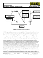
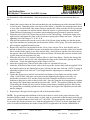
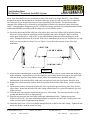
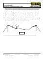
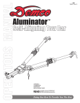
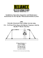
Reliance Industries, LLC
Installation, Operation, Inspection and Maintenance
Instructions for the Skyline™ Horizontal Lifeline System
6350
Portable Structural Steel Lifeline System using
3/8 – 7x19 Steel Wire Rope with Ratchet Tensioner and the
Skyline™ Shock Absorber
Reliance Industries, LLC
PO Box 140008
Denver, CO 80214
Ph. (800) 488-5751
Ph. (303) 424-8650
Fax (303) 424-8670
US Patent #6,338,399 and other Patents Pending
User Instructions
6350 Skyline™ Structural Steel HLL System
Reliance Industries, LLC
Important Instructions!
These instructions must be kept on file and available for the users reference at
all times. The users must read and fully understand these instructions or have
the instructions explained in detail before using this equipment. Failure to
observe these instructions could result in serious injury or death.
Prior to use, all workers must be trained in the proper use of all systems and
equipment.
A Training and Instruction review should be repeated at regular intervals.
A rescue plan must be prepared; the workers must be trained in its use, and
rescue equipment must be on hand prior to any use of this horizontal lifeline
system.
Any questions regarding these instructions should be directed to:
Reliance Industries, LLC
PO Box 140008
Denver, CO 80214
Ph. (800) 488-5751
Ph. (303) 424-8650
Fax (303) 424-8670
Reliance Industries, LLC
Rev: B
Date: 07/21/04
Denver, CO 80214
Ph. (800) 488-5751
Doc.: M-6350
Fax (303) 424-8670
Page 2 of 24
User Instructions
6350 Skyline™ Structural Steel HLL System
Reliance Industries, LLC
Table of Contents
IMPORTANT INSTRUCTIONS! .............................................................................................................................................. 2
SYSTEM DESCRIPTION........................................................................................................................................................... 5
ANCHORAGE POINTS.............................................................................................................................................................. 6
HORIZONTAL LIFELINE SYSTEM COMPONENTS ......................................................................................................... 6
PERSONAL FALL ARREST EQUIPMENT USED WITH HORIZONTAL LIFELINES ................................................. 7
INSTALLATION LAYOUT CONSIDERATIONS .................................................................................................................. 8
INSTALLATION ......................................................................................................................................................................... 9
TOOLS REQUIRED FOR A TYPICAL STRUCTURAL STEEL SYSTEM INSTALLATION....................................... 13
HLL INSTALLATION PROCEDURES ................................................................................................................................. 14
LIFELINE INSTALLATION UTILIZING STRONGBACK BEAMS ................................................................................ 19
INSTALLING THE 3093 ANCHOR CLAMP ........................................................................................................................ 19
TRAINING ................................................................................................................................................................................. 20
PLANNING FOR RESCUE...................................................................................................................................................... 20
INSPECTION............................................................................................................................................................................. 21
SERVICING ............................................................................................................................................................................... 22
WARNINGS AND LIMITATIONS ......................................................................................................................................... 22
INSPECTION LOG FOR HLL SYSTEMS............................................................................................................................. 23
SKYLINE™ HORIZONTAL LIFELINE DIAGRAM........................................................................................................... 24
Reliance Industries, LLC
Rev: B
Date: 07/21/04
Denver, CO 80214
Ph. (800) 488-5751
Doc.: M-6350
Fax (303) 424-8670
Page 3 of 24
User Instructions
6350 Skyline™ Structural Steel HLL System
Reliance Industries, LLC
Important OSHA Regulations Covering the Use of Horizontal
Lifeline Systems
OSHA 1910.66 Subpart M – 1926.502 (d)(8):
Horizontal Lifelines shall be designed, installed, and used under the supervision of a qualified
person as part of a complete fall arrest system, which maintains a safety factor of at least two.
OSHA 1910.66 (b):
“Qualified Person” means one with a recognized degree or professional certificate and extensive
knowledge and experience in the subject field who is capable of design, analysis, evaluation, and
specifications in the subject work, project, or product.
OSHA 1910.66 (b):
“Competent Person” means a person who is capable of identifying hazardous or dangerous
conditions in the personal fall arrest system or any component thereof, as well as in their application
and use with related equipment
OSHA 1910.66:
Personal fall arrest systems shall be rigged such that an employee can neither free-fall more than 6ft. nor contact any lower surface.
OSHA 1910.66 (n):
The sag in the lifeline should be minimized to prevent the connecting piece of equipment (selfretracting lanyard or other appropriate personal fall arrest device) from sliding down the lifeline to a
position, which creates a swing hazard during a fall arrest.
OSHA Standards, Interpretations and Compliance Letters, 02/09/1995-Criteria for personal fall arrest
systems:
The free-fall distance is limited to 6 feet. The deceleration distance must not exceed 42 inches;
lifeline elongation is not included in deceleration distance; and the total fall distance is unregulated
except that the employee cannot make contact with a lower level…The safety factor of two should
be applied based on the anticipated maximum arrest force, not the fall energy.
Reliance Industries, LLC
Rev: B
Date: 07/21/04
Denver, CO 80214
Ph. (800) 488-5751
Doc.: M-6350
Fax (303) 424-8670
Page 4 of 24
User Instructions
6350 Skyline™ Structural Steel HLL System
Reliance Industries, LLC
System Description
The Skyline™ Horizontal Lifeline System P/N 6350 is designed for use as a portable horizontal lifeline
system where structural steel is present, such as during building construction. Its’ lightweight materials
allow for easy installation and removal, yet the rugged construction allows for a long service life in
demanding construction environments. The lifeline is constructed of 3/8-in. – 7x19 wire rope and is
available in both galvanized (IPS) and stainless steel versions and uses a unique ratchet load binder for
rapid tensioning of the Skyline™ lifeline to the proper load. It is designed to enable the user to attach to
an engineered fall arrest system in work areas where no overhead anchor points exist. The system, in
general, is designed for use by up to 4 persons at the same time, and can span distances up to 200-ft.
However, span length and number of persons on the system determine input energy (and therefore, final
line tension) and not all combinations of span lengths and number of workers are possible. The user must
consult the manufacturer for exact system parameters for each installation, or in the event that the system
is moved. System parameters are provided in the form of computer generated load and Minimum
Required Clearance (MRC) data that is traceable to our data and test results for each system installation.
The computer generated designs are prepared from verifiable test data and include a 2-ft. safety factor for
Minimum Required Clearance for a vertical fall, and a 2 to 1 Safety Factor over the minimum cable
breaking strength for maximum allowable line tension.
This system design is predicated on the use of a full-body harness for the worker, double-action, singlelocking snap hooks to attach to the lifeline, and a shock absorbing vertical lifeline or self-retracting
lanyard (SRL) with a 900 lb. Maximum Arrest Force (MAF). Non-shock absorbing lanyards and
retractables that do not have “slip-clutch” type internal shock absorbers with a 900 lb. maximum MAF are
NOT allowed for use as vertical lifelines on this system. Any attachment to the horizontal lifeline must
transfer fall arrest forces to the body through the dorsal d-ring of the full body harness only. Harness side
and chest d-rings are not allowable lanyard connection points.
All Skyline™ HLL systems are supplied with an integral shock absorber in the line and no system may be
used without one. The four main functions of the shock absorber are:
1.
2.
3.
4.
It adds energy capacity to the system to increase the safety of short horizontal lifelines.
It adds hysterisis (friction) to the system to absorb rebound energy.
It decreases low sag angle amplification by controllably elongating the horizontal lifeline.
It allows the cable to be tuned (or pre-loaded to a higher initial line tension) to force the cable to
absorb energy at a higher rate.
The shock absorber has a built in spring-loaded tensioner that indicates when the proper pre-tension has
been achieved. Normally the pre-tension is set at 1000-lb. but may be changed for specifically designed
applications.
When a system is installed, the pre-tension must be set according to the installation instructions. Not all
systems are perfectly rigid; therefore, pre-tension may change over time. Prior to each use, the worker
Reliance Industries, LLC
Rev: B
Date: 07/21/04
Denver, CO 80214
Ph. (800) 488-5751
Doc.: M-6350
Fax (303) 424-8670
Page 5 of 24
User Instructions
6350 Skyline™ Structural Steel HLL System
Reliance Industries, LLC
must check the pre-tension of the system and adjust it accordingly. When the pre-tension of a system is
closely controlled, the fall distance and final line tension are easily predictable. Knowing that the pretension of a horizontal lifeline is set correctly is of utmost importance to the predictability and safety of
the system.
Anchorage Points
The strength of horizontal lifeline anchorage points must be at least two times the anticipated line tension.
This strength must be certified by a qualified person and must be verifiable by either calculation or
testing. Anchorage connectors must be selected carefully. Eyebolts should not be used if they will be
loaded at an angle to their axis, unless the loads fall within design parameters for such use. Weld-on lugs
should not be less than 1/2-in. in width and should not be made of steel with less than 50,000-PSI yield
strength. The proper stress areas and weld areas must be calculated to assure proper safety. If in
question, consult Reliance engineering staff for proper design requirements.
Horizontal Lifeline System Components
The Skyline™ Horizontal Lifeline System for Structural Steel consists of the following standard approved
and compatible components:
1 ea. Model 6310-1 Portable Skyline™ Horizontal Lifeline Kit which includes the following
components:
•
•
•
•
•
1 ea. Model 6000 Skyline™ Shock Absorber (stainless steel)
1 ea. Model 6050 Steel In-Line Cable Clamp (zinc plated carbon steel)
5 ea. Model 6062 1/2-in. bow shackles (stainless steel)
1 ea. Model 6090 3-in. Ratchet Assembly
1 ea. Model 6092 10-ft. Ratchet Strap, 3-in. wide
(The above components in the 6310-1 kit, along with the appropriate length of cable may be utilized as
the basic building block for other Skyline™ Portable Lifeline systems, such as the Looped Rebar HLL for
highway applications; the Stanchion Rebar HLL system for concrete applications, and to existing
structural steel columns utilizing the 3093 beam clamp and associated 3091 by-pass assemblies; and other
applications.)
2 ea. Model 6066 5/8-in. bow shackles (stainless steel)
2 ea. End Stanchions, 2-in. square steel tube, (60-, 72-, or 84-in. tall depending on HLL system
design)
2 ea. Model 6077 3/8-in. x 21-ft. Tie-back cable assembly
2 ea. Model 6240 HLL Stanchion I-beam Clamp, for flanges 4- to 14-in. wide
2 ea. Model 3093 HLL Anchor Clamp
(This clamp (Model 3093) can be used for either termination of the 6077 tie-back assembly or for direct
connection to the 6310-1 Portable Skyline™ Horizontal Lifeline Kit)
Reliance Industries, LLC
Rev: B
Date: 07/21/04
Denver, CO 80214
Ph. (800) 488-5751
Doc.: M-6350
Fax (303) 424-8670
Page 6 of 24
User Instructions
6350 Skyline™ Structural Steel HLL System
Reliance Industries, LLC
To complete the Skyline™ Horizontal Lifeline System, a Reliance Industries wire rope must also be used.
The cable options are as follows:
1 ea. Model 6070 3/8-in. – 7x19 IPS galvanized wire rope
or
1 ea. Model 6072 3/8-in. – 7x19 stainless steel wire rope
where the length of your cable is dependent on the specific horizontal lifeline system design.
The above list of components represent those items that are most commonly used in horizontal lifeline
system designs for structural steel applications. Reliance maintains a varied inventory of HLL Stanchion
I-beam Clamps that accommodate structural steel up to 28-in. in width with up to 2-in. thick flanges in
both top- and bottom-flange mounting versions. Optional 4 lug End Stanchions are also available for the
termination and continuation of crossing horizontal lifelines in work areas that possess adequate structural
strength and geometry. Not all systems will use all of these components, and some designs may require
additional components not shown (additional tie-back cables, bypass stanchions, or clamps, for example).
Please contact Reliance Engineering at (303) 424-8650 for help in designing and selecting the proper
equipment for an application.
The actual selection of components and options for the design of a horizontal lifeline system should only
be performed by a Qualified Person, or a state registered Professional Engineer who is experienced in the
design and use of safety systems.
The Skyline™ Horizontal Lifeline system is designed for use with the approved, above listed components
only. Substitutions or replacements with non-approved components will endanger the system integrity
and may affect the safety and reliability of the total system.
Personal Fall Arrest Equipment Used with Horizontal Lifelines
It is of utmost importance in the design of horizontal lifelines to be able to predict the vertical fall arrest
forces that will be imposed on a lifeline during a fall. Normally, the lifeline will elongate under
increasing tension until the horizontal lifeline imposes a 900-lbf. vertical force on the shock absorbing
lanyard and then the lanyard will begin to rip out (or extend in the case of a SRL) until all of the fall
energy has been absorbed. For multiple persons this force increases as a multiple of 900-lbs. The shockabsorbing lanyard, therefore, is vital in predicting and limiting horizontal lifeline tension. Only shock
absorbing lanyards (or SRLs) with 900-lb. Maximum Arrest Force are allowed for use with this system.
Care should also be used in selecting and fitting a harness for use with horizontal lifeline systems. Due to
the HLL sag height, additional distance required for clearance when using horizontal lifeline systems is
often the limiting factor in determining whether a HLL system can be used for a particular application.
Harnesses with sewn down or large non-moving back pads can limit as much as 1 ft. of back pad slippage
during fall arrest, providing additional clearance for safety. If the system will be used where a worker
Reliance Industries, LLC
Rev: B
Date: 07/21/04
Denver, CO 80214
Ph. (800) 488-5751
Doc.: M-6350
Fax (303) 424-8670
Page 7 of 24
User Instructions
6350 Skyline™ Structural Steel HLL System
Reliance Industries, LLC
could encounter a head first free-fall, a non-secured back pad can slide down the webbing to the small of
the back, allowing the worker to fall out of the harness through the top by allowing the harness straps to
slip over the shoulders. For this reason, we recommend careful consideration of both the type of work,
and the manner in which it will be performed prior to the selection of personal fall protection equipment.
Installation Layout Considerations
Most HLL installations consist of either single-span or multi-span systems. Single-span systems consist
of two end anchorages with a single HLL lifeline attached between them. Multi-span systems consist of
two end anchorages and multiple intermediate (bypass) supports through which the cable passes, but
which it is not attached. Normally the bypasses consist of a structure that will allow a lanyard snap to
pass through without allowing the cable to become disconnected without damaging the cable. The bypass
fittings are also designed to take loads imparted by system deployment. Input energy into an HLL system
during fall arrest is usually determined by span length. The longer the span, the farther a person will fall
during fall arrest and therefore, the greater the input energy. The more people that fall on a system at one
time, the greater the falling weight and this also increases the input energy. In order to limit input energy
into a system, one must limit the number of persons on a system and also limit the span length (the peak
line tension that a horizontal lifeline experiences during a fall arrest goes up as span length increases and
must be monitored to ensure it does not go past the 2 to 1 Safety Factor limit of the lifeline system). On
the other hand, the cable, having the greatest energy capacity (or ability to absorb energy) of all the
components of a system due to its ability to strain under stress, must be long in order to absorb the
greatest amount of energy. Therefore, the safest way to rig and assemble a horizontal lifeline system is to
use the longest cable length possible with bypass supports located to reduce sub-span length to as short as
possible. Only minimum required clearance limits (MRC) should be used to determine maximum
allowable line length.
Reliance Industries, LLC
Rev: B
Date: 07/21/04
Denver, CO 80214
Ph. (800) 488-5751
Doc.: M-6350
Fax (303) 424-8670
Page 8 of 24
User Instructions
6350 Skyline™ Structural Steel HLL System
Reliance Industries, LLC
Installation
Installation of horizontal lifeline systems should be done under the supervision of a Qualified Person
trained in their function and use. Use only parts that have been qualified as compatible components by
Reliance Industries. Install the system only as specified in the system parameter documents prepared by
the computer program system. Ensure that the minimum anchorage strength is at least 2 times the
anticipated load called out in the system parameter documents. Have the anchorages certified by a
qualified person and keep documentation on hand. HLL calculations for minimum required clearance
(MRC) are measured vertically below the walking/working surface and assume that the horizontal lifeline
is at least 5-ft. above the walking/working surface (unless otherwise specified) in order to limit free-fall to
6-ft. or less as required by OSHA.
HAZARDOUS SITUATIONS: When working on a structure, do not take unnecessary risks such as
jumping or reaching too far from the edge of the structure. Be aware of hazards in your work area
such as electrical hazards or moving machinery. Do not allow the connecting subsystem to pass under the
arms or between the feet. Never climb above the Skyline™ HLL system or far off to the side since
inadequate fall clearance or a swing fall could result.
Always install lifelines horizontally where all end anchorages and bypass supports are at the same
elevation. Never change vertical or directional slope without close supervision of Reliance Engineers.
Always install the system per the system parameter documents and NEVER change span length, sub-span
length, or number of people allowed on the system. Remember, horizontal lifeline dynamics change with
any changes to span length, or number of people allowed on the system. Any changes require a new
design, and MUST be approved by a Qualified Person.
Reliance Industries, LLC
Rev: B
Date: 07/21/04
Denver, CO 80214
Ph. (800) 488-5751
Doc.: M-6350
Fax (303) 424-8670
Page 9 of 24
User Instructions
6350 Skyline™ Structural Steel HLL System
Reliance Industries, LLC
The system may be installed with the cable running parallel with the axis of the structural steel such as on
the top bay of a pipe-rack (see Figure 1 below).
Figure 1 – Lifeline running parallel to the structural steel
The system may also be installed on structural steel beams that run perpendicular to the axis of the HLL
such as on the structure shown below (see Figure 2). Additional consideration should be given to the
placement of tieback assemblies in this application due to the load amplification and the resulting
potential twisting effect of the tie-backs on the structural beams. Also, care must be taken not to overload
longer beams when connecting at their midpoints. This configuration could decrease the tieback
anchorage strength as a function of unsupported beam length and should be approved by your field
engineer or other qualified professional engineer. Maximizing tieback strength can be accomplished in
lateral beams by attaching dual tieback anchorages as close to the structural joints (beam ends) as
possible.
Reliance Industries, LLC
Rev: B
Date: 07/21/04
Denver, CO 80214
Ph. (800) 488-5751
Doc.: M-6350
Fax (303) 424-8670
Page 10 of 24
User Instructions
6350 Skyline™ Structural Steel HLL System
Reliance Industries, LLC
Figure 2 – Lifeline running perpendicular to the structural steel
Reliance Industries, LLC
Rev: B
Date: 07/21/04
Denver, CO 80214
Ph. (800) 488-5751
Doc.: M-6350
Fax (303) 424-8670
Page 11 of 24
User Instructions
6350 Skyline™ Structural Steel HLL System
Reliance Industries, LLC
The layout of the most typical components for a standard Structural Steel System layout are:
Figure 3 – Components of a typical Structural Steel System
1.
2.
3.
4.
5.
Skyline™ Shock Absorber, P/N 6000
3-in. Ratchet Assembly, P/N 6090
3-in. x 10-ft. Ratchet Strap, P/N 6092
1/2-in. Bow Shackle, P/N 6062
3/8-in. wire rope, P/N 6070 (gal),
or 6072 (SS)
6. In-Line Cable Clamp, P/N 6050
7. 5/8-in. Bow Shackle, P/N 6066
8. Tie-back Cable Assembly, P/N 6077
9. HLL Anchor Clamp, P/N 6093 *
10. HLL Beam Clamp, P/N 6240
11. End Stanchion (5-, 6-, or 7-ft.)
12. Structural Steel I-Beam
* P/N 6093 may be replaced with 6235 Underslung HLL Beam Clamp for situations where the top flange
is inaccessible, or P/N 6240 HLL Beam Clamp.
Reliance Industries, LLC
Rev: B
Date: 07/21/04
Denver, CO 80214
Ph. (800) 488-5751
Doc.: M-6350
Fax (303) 424-8670
Page 12 of 24
User Instructions
6350 Skyline™ Structural Steel HLL System
Reliance Industries, LLC
Tools Required for a Typical Structural Steel System
Installation
The tools required for a typical Structural Steel Lifeline System Installation include, but are not limited to
the following:
Box end and combination wrenches
• 11/16-in. (for cable clamps)
• 3/4-in. (for combination clamp)
• 5/8-in. (for In-Line Cable Clamp)
• 15/16-in. (for cable clip on tie-back assembly)
• 1-1/8-in. (for 6240 Stanchion Receiver Beam Clamp)
Ratchets and sockets, in a 3/8-in. or 1/2-in. drive size:
• 3/4-in. (for the combination clamp)
• 5/8-in. (for the In-Line Cable Clamp)
• 11/16-in. (for the cable clip on tie-back assembly)
Miscellaneous tools:
• Torque ratchet or wrench (preferred)
• Crescent wrenches; large (up to 1-3/4-in.), and small (up to 3/4-in.)
• Screwdrivers (used for rigging screw tightening on tie-back assy. One must be large Phillips to fit
hole for final tightening
• Hammer (to tighten handle of 3093 Anchor Clamp)
• Permanent marking pen to mark cable & affix labels
• Lithium grease for stainless steel thread lubricant on rigging screw
• Tape measure
Reliance Industries, LLC
Rev: B
Date: 07/21/04
Denver, CO 80214
Ph. (800) 488-5751
Doc.: M-6350
Fax (303) 424-8670
Page 13 of 24
User Instructions
6350 Skyline™ Structural Steel HLL System
Reliance Industries, LLC
End Stanchion
Tie-back Cable
End Stanchion
HLL Anchor
Clamp or HLL
I-Beam Clamp
Skyline Horizontal
Lifeline
HLL Stanchion
I-beam Clamp
HLL Stanchion
I-beam Clamp
Figure 4
HLL Installation Procedures
NOTE: Approved fall protection must be worn during Skyline™ lifeline installation at all times. Do not
use the horizontal lifeline or its anchorages as personal fall protection anchorages until the system has
been completely installed, inspected, and approved for use by a Qualified Person. Where possible,
Reliance recommends the use of man-lifts or safe access to a guarded structure for rigging end
terminations and erection of the Skyline Portable system. When engineering controls are unavailable to
rig the lifeline, perform a JSA (job safety analysis) prior to the installation to determine all hazards and
establish “safe-task” procedures to minimize the risks present. In addition to the typical fall protection
solutions, consider remote anchorage connectors (such as Skyclamp™ and remote connection pole for
utilizing anchorages up to 20-ft. overhead), Screw-jack fixed beam clamps for installing a localized
anchorage point at the same level as the harness dorsal d-ring, or sliding beam clamps to prevent falls to
lower levels or minimize the effect of pendulum-swing falls. Although positioning lanyards have fallen
into disfavor because of misuse, consider their use essential as primary-fall protection while pretensioning the line on un-guarded platforms or structures. A qualified design person should consider if an
erected single-span lifeline (limited to 1 or 2 installers) could be utilized safely as a fall protection system
to erect other sub-span bypasses and minimize risk for installers. One option for providing temporary fall
protection to the installer during installation is for a SINGLE worker to attach to a bow shackle in the
bottom hole of an end stanchion using a 6-ft. shock-absorbing lanyard (maximum length) only after the
6240 HLL Anchor Clamp has been properly tightened to 75- to 90-ft. lb. and the end stanchion has been
bolted into place. The only method of attachment permitted in this case is to use a carabiner passed
through the eye of the shock-absorbing lanyard snaphook (not the gate opening) and the bow shackle in
Reliance Industries, LLC
Rev: B
Date: 07/21/04
Denver, CO 80214
Ph. (800) 488-5751
Doc.: M-6350
Fax (303) 424-8670
Page 14 of 24
User Instructions
6350 Skyline™ Structural Steel HLL System
Reliance Industries, LLC
the bottom hole of the end stanchion. Only one person may be attached to any one-end stanchion at a
time.
1. Identify the location where the first end stanchion (the end attachment point of the horizontal lifeline)
is to be located. Depending on the exact layout of the lifeline, it should be far enough down the beam
so as to allow for the tieback cable anchor clamp to attach to the I-beam such that it will be positioned
properly. At a minimum, the tieback distance should be equal to or greater than the stanchion height.
Contact Reliance Engineering for assistance in determining proper placement if questions remain.
2. Widen the jaws of the 6240 I-beam clamp to slide over the I-beam flange. Position the clamp at the
right location, and tighten the clamp to the I-beam after squaring the clamp to the beam. Torque the
tightening nut of the clamp to 75- to 90 -ft. lb.
3. Slide the end stanchion tube into the receiver tube of the I-beam clamp, making sure that the anchor
lugs of the stanchion are pointing the direction that the lifeline will be going. Secure the stanchion inplace using the supplied bolt and lock nut.
4. Remove the cotter lock ring and bolt from the 5/8-in. (Note: only the 5/8-in. bow shackles may be
utilized on the tie-back assemblies because of the higher line tensions seen in the cables.) bow shackle
that is attached to the rigging screw of the tieback cable. Attach the bow shackle to the lower hole on
the opposite side of the end stanchion from where the lifeline will attach and secure the tie-back cable
in place using the bolt and cotter lock ring.
5. Widen the jaws of the 3093 Anchor Clamp to slide over the I-beam flange. Position the clamp at the
required location for the tie-back cable, and tighten the clamp to the I-beam after squaring the clamp
to the beam. Torque the tightening nut of the clamp to 40-ft. lb.
6. Adjust the rigging screw of the tie-back cable so that it is extended half way out.
7. Attach the second end of the tie-back cable to the d-ring of the Anchor clamp with the supplied 5/8-in.
bow shackle and secure the shackle bolt in place with the nut and cotter lock ring. NOTE: If using an
adjustable length tie-back cable (6077), the length should be adjusted prior to attaching to the 3093
Anchor Clamp.
8. Tighten the rigging screw until the end stanchion just begins to lean slightly towards the anchor
clamp. If the tie-back cable does not become taut after tightening the rigging screw fully, it is
permissible to loosen the 3093 Anchor Clamp and slide it along the beam away from the end
stanchion to help take up slack in the tie-back cable. Once the clamp has been repositioned, re-tighten
the clamp to the I-beam and re-tension the tie-back cable. NOTE: This method of sliding the Anchor
Clamp along the I-beam will only work for lifeline systems that are installed parallel to the I-beams;
for systems that are installed perpendicular to the I-beams, the length of the adjustable tie-back cable
must be changed.
9. Repeat Steps 1 through 8 for the opposite end of the horizontal lifeline.
NOTE: The positioning and installation of the tie-back cables is critical to the proper function of the
horizontal lifeline system. For most systems, tie-back cable are positioned so that the angle formed by the
surface of the I-beam and the tie-back cable is 45° OR LESS. This means that the Anchor Clamp MUST
be secured to the I-beam a distance away from the end stanchion AT LEAST as far the Stanchion is tall
(for a 60-in tall End Stanchion, the Anchor Clamp MUST be tightened to the I-beam a MINIMUM of
Reliance Industries, LLC
Rev: B
Date: 07/21/04
Denver, CO 80214
Ph. (800) 488-5751
Doc.: M-6350
Fax (303) 424-8670
Page 15 of 24
User Instructions
6350 Skyline™ Structural Steel HLL System
Reliance Industries, LLC
60-in. away from the Receiver to ensure the tie-back cable angle is no larger than 45°). Some lifeline
designs may require the attachment of 4 tie-back cables per system (2 each per end). This is especially
true when travel or work performed is not in close proximity to the Lifeline. The maximum lateral
strength of the lifeline may be achieved by utilizing dual tie-backs to the structural joints (steel beam
ends). Contact Reliance Engineering at (303) 424-8650 with any questions concerning horizontal lifeline
installation BEFORE proceeding with the setup or use of any lifeline system.
10. Layout the horizontal lifeline cable on a flat surface near where the lifeline will be installed (directly
below the I-beam where the stanchions will be installed) and remove all bends. Inspect cable for
crush spots, broken wires, weld strikes, or any other deformity that may affect the integrity of the
cable. Damaged cables must be removed from service immediately from service. Position the eye end
of the wire rope so that it is about 7-ft. (see Figure 5) away from the location of one of the end
stanchions.
Figure 5
11. At the opposite end stanchion, locate the spot on the wire rope where it would contact the anchor lug
of the stanchion. A plumb line or laser level may be used to help identify this spot on the cable if the
cable has been layed out some distance below where the stanchions were installed, otherwise
readjustment of the end-line cable clamp on a trail and error basis may be required. Mark the spot.
12. Remove the 6 bolts and lock washers from the top plate of the In-line cable clamp. Set the top plate
aside.
13. On the mark you have measured off, place the wire rope into the grooved lower plate of the In-line
cable clamp. Insure that the end of the cable clamp with the hole in it is placed towards the free end
of the wire rope.
14. Twist the wire rope and press down into the grooves of the clamp. The wire rope may have to be
twisted and untwisted for it to align properly.
15. Place the top plate onto the lower plate, and begin tightening the bolts. Tighten the top plate
EVENLY to 35 ft-lb. For more detailed information on using the In-Line Cable Clamp, please refer
to the “In-Line Cable Clamp Instruction Manual”.
16. Attach the bolt of one 1/2-in. bow shackle through the hole of the In-line cable clamp. Tighten the nut
and secure in place with the cotter lock ring.
Reliance Industries, LLC
Rev: B
Date: 07/21/04
Denver, CO 80214
Ph. (800) 488-5751
Doc.: M-6350
Fax (303) 424-8670
Page 16 of 24
User Instructions
6350 Skyline™ Structural Steel HLL System
Reliance Industries, LLC
17. Insert a second 1/2-in. bow shackle through the bow of the shackle attached to the In-line cable clamp.
Using the shackle bolt, attach the bow shackle to the top hole in the End Stanchion. Replace the nut
and cotter lock ring.
18. Attach one 1/2-in. bow shackle through the triangular d-ring of the 10-ft. long ratchet strap, and the
eye of the wire rope. Tighten the bow shackle nut and secure with the cotter lock ring.
19. Insert a 1/2-in. bow shackle through the eye of the Skyline shock absorber and the top hole of the
second End Stanchion. Secure the bolt with the nut and replace the cotter lock ring.
20. Remove the clevis pin of the Skyline shock absorber and insert the triangular d-ring of the ratchet load
binder into the clevis. Replace the clevis pin and cotter lock ring.
21. Begin lifting the horizontal lifeline cable assembly to its intended position (see Figure 6). If bypass
stanchions are being used, the cable must be placed through the center of the bypass fittings before the
cable is properly tensioned. Pass the free end of the ratchet strap into the slot of the ratchet. Pull the
free end of the ratchet strap to help remove slack from the lifeline cable.
Figure 6
22. While holding the ratchet strap tight, begin tensioning the lifeline, using the ratchet handle.
Reliance Industries, LLC
Rev: B
Date: 07/21/04
Denver, CO 80214
Ph. (800) 488-5751
Doc.: M-6350
Fax (303) 424-8670
Page 17 of 24
User Instructions
6350 Skyline™ Structural Steel HLL System
Reliance Industries, LLC
23. Tighten the ratchet load binder until the line tension just releases the load-indicating washer of the
shock absorber to spin free. This washer is located just under the eye of the shock absorber (see
Figure 7). A freely spinning washer indicates that the cable has been pre-tensioned to 1000 lbf.
Figure 7
24. Check that the webbing of the ratchet strap has made at least one complete revolution on its mandrel
before the correct line tension has been reached. If it has not made a full revolution, release the
tension, let 1- to 2-in. of the ratchet strap to slip back out of the load binder and retighten. The strap
should now make at least one full revolution before the lifeline is properly tensioned. At least one full
revolution is necessary for the tensioner to overcome the maximum load with out slipping.
25. Inspect the installation for any defects, such as missing parts, damage, proper anchorage strengths and
configuration, proper pre-tensioning, proper cable alignment, proper elevation, defective or noncompatible components. DO NOT authorize system use if any defects or discrepancies are found.
Check system installation parameters with system installation parameter documents to assure that the
correct installation has been performed.
26. Once the system passes all checks by the competent person, the system may be approved for use, and
labeled with a permanent identification tag referencing the following information:
a. Identification number that will tie the lifeline to the correct computer generated design
documents that identify the original design parameters.
b. Date of installation.
c. Total authorized span length and sub-span length.
d. Total number of people allowed on the system at one time.
e. The minimum required clearance (MRC) below the walking/working surface.
f. The anticipated maximum line tension.
27. A separate tag should also be added indicating date of last inspection by the competent person.
Reliance recommends daily inspection, especially on a multi-contractor jobsite and will be happy to
assist you in selection of compatible tags.
Reliance Industries, LLC
Rev: B
Date: 07/21/04
Denver, CO 80214
Ph. (800) 488-5751
Doc.: M-6350
Fax (303) 424-8670
Page 18 of 24
User Instructions
6350 Skyline™ Structural Steel HLL System
Reliance Industries, LLC
Lifeline Installation Utilizing Strongback Beams
In some installations where it is not possible to use tieback assemblies, or where access is required to be
extended to the end of the structure, it is possible to install the lifeline system without the use of tieback
cables through the use of the strongback beam. The following sketch shows a typical HLL installation
using a strongback beam. Strongbacks transfer the lifeline tension imposed at the top of the stanchion
into the structural steel of the walking/working surface. The strongback is supplied in one length and can
be used for 5-, 6-, and 7-ft. tall stanchions, and can attach to all existing stanchions and beam clamps
without requiring any additional hardware. Care should be taken not to exceed 7,250-lb. of lifeline
tension for these installations. This type of system is used typically for lifeline systems where the
structural steel runs parallel to the lifeline. This system is not recommended for structures where the
structural steel runs perpendicular to the lifeline cable, unless the beam loading requirements are certified
by a Professional Engineer (PE). Such applications will require custom length strongbacks; please
consult Reliance Engineering for more information.
Installing the 3093 Anchor Clamp
The 3093 Skyline™ Anchor Clamp is designed as a portable anchorage that can be temporarily installed
to a structural I-beam to provide a rigid personal fall arrest (PFA) anchorage for fall arrest for one person
only or as an anchorage for an HLL system, or as an attachment point for a tie-back cable of an HLL
system. Note: the 3093 Anchor Clamp may be used for only one of these purposes at any one time; it
may not, for example, be used as a personal fall arrest anchor point while it is also has a horizontal lifeline
Reliance Industries, LLC
Rev: B
Date: 07/21/04
Denver, CO 80214
Ph. (800) 488-5751
Doc.: M-6350
Fax (303) 424-8670
Page 19 of 24
User Instructions
6350 Skyline™ Structural Steel HLL System
Reliance Industries, LLC
tie-back cable attached to it. It can be attached to the top or bottom flanges of either horizontal or vertical
I-beams when properly torqued to 40-ft-lbs.
To attach the Beam Clamp, loosen the hand-knob to desired width, slip over the I-beam flange and tighten
the hand-knob as to 40 ft-lb. Check tightness again prior to each use. DO NOT stand on either the nut or
the threaded rod or the handknob. DO NOT use if the clamp does not grip the beam securely enough to
prevent any side movement up or down the beam.
Removal is the opposite of installation and should only be performed once it has been verified that there
are no individuals attached to the clamp or to a horizontal lifeline attached to the clamp that may be put at
risk by the clamps removal.
Training
It is the responsibility of the employer to train all workers prior to using this system (per OSHA 1926.503
(a)(1)). The employer shall provide a training program for each employee who might be exposed to fall
hazards. The program shall enable each employee to recognize the hazards of falling and shall train each
employee in the procedures to be followed in order to minimize these hazards.
Even when using a full body harness, a quick rescue is critical. To ensure a quick response, a method
must be in place to ensure a fallen worker is quickly noticed and his rescue effected.
It is the responsibility of all users of this equipment to understand these instructions, and to be trained in
the correct installation, use, and maintenance of this equipment. These individuals must be aware of the
consequences of improper installation or use of this equipment. This user manual is not a substitute for a
comprehensive training program. Training must be provided on a periodic basis to ensure profficiency of
the users.
The employer shall assure that, as necessary, each employee has been trained by a competent person
qualified in the following areas:
a.
b.
c.
d.
e.
OSHA regulations governing the use of horizontal lifelines.
Ability to recognize potential fall and workplace hazards.
Method of inspection of safety equipment.
Rescue procedures.
Installation and removal techniques.
Planning for Rescue
Prior to system use, a rescue plan must be prepared, the workers must be trained in its use, and the rescue
equipment must be on hand to implement it in case of a fall.
Reliance Industries, LLC
Rev: B
Date: 07/21/04
Denver, CO 80214
Ph. (800) 488-5751
Doc.: M-6350
Fax (303) 424-8670
Page 20 of 24
User Instructions
6350 Skyline™ Structural Steel HLL System
Reliance Industries, LLC
Typical rescue plans include (but are not limited to) the following items:
1. List of equipment that must be readily accessible in the event of an emergency and the names of
those workers certified to use or operate that equipment.
2. Emergency contact phone numbers (ambulance, hospital, fire department…) and a means to
contact them (cell phone, emergency radio).
3. List of employees on the site, and the specific tasks they will perform to effect the rescue.
The equipment that will be used to aid in the rescue of any worker must be attached to structural
anchorages independent of those used for the horizontal lifeline system. During installation of horizontal
lifeline anchorages, tie-off and equipment attachment hardpoints should be attached, and also clearly
marked in such a manner as to provide a means to rescue a worker in any position along the lifeline
system.
With the number of potential scenarios and locations for a worker requiring rescue, an on-site rescue team
is advantageous. This group of individuals is given the tools, both in equipment and technique, so they
can perform a successful and efficient rescue. It is important to provide training on a periodic basis to
ensure skills learned are kept current.
Inspection
Prior to each use, the worker must inspect the system for any physical damage, wear, corrosion, or
malfunctioning parts. Check the shock absorber for deployment by looking to see if the black slide
bearing under the shock absorber eye is exposed. If the washer on the shock absorber freely rotates when
not in tension (indicating either misuse or over-tensioning) the shock absorber must be replaced to verify
proper pre-tensioning of the horizontal lifeline. Once the shock absorber is deployed, its energy capacity
is used up, and it cannot be reset. If the shock absorber deploys, the entire system has seen a fall arrest
load and must be removed from service until it is inspected by a competent person who either replaces or
repairs and re-certifies the components for use on the system. Once deployed, shock absorbers are not reusable, and must be replaced. With deployment of the shock absorber, it is critical for a competent person
to inspect all lifeline components for cracks, distortion of the structural anchorages and connectors. In
addition to a normal cable inspection, inspect the swaged eye of the lifeline cable to verify it retains its’
original tear-drop shape. Any variation from the original shape indicates excessive load on the cable and it
should be replaced. If an inspection reveals a problem or unsafe condition, remove the entire system from
service until it can be re-certified by a competent person.
The worker, who must also check the pre-tension prior to each use, must inspect all system components.
A formal inspection must be carried out a minimum of once each year, and be formally documented and
kept on file with the system parameter documents.
Reliance Industries, LLC
Rev: B
Date: 07/21/04
Denver, CO 80214
Ph. (800) 488-5751
Doc.: M-6350
Fax (303) 424-8670
Page 21 of 24
User Instructions
6350 Skyline™ Structural Steel HLL System
Reliance Industries, LLC
Servicing
A qualified person trained in the inspection and servicing of system components must carry out servicing
of this system. The company’s safety officer should maintain a record log of all servicing and inspection
dates. The system and all components must be withdrawn from service if subjected to fall arrest forces.
Those components may be returned to service only after being certified by a qualified person. Only
original Reliance Industries equipment and replacement parts are approved for use in this system. Contact
Reliance Engineering with questions and when in need of assistance.
Warnings and Limitations
Proper care should always be taken to visually scan the work area prior to use. Remove any obstruction,
debris, and other materials from, and beneath the work area that could cause injuries or interfere with the
operation of this system. Be cautious of swing fall hazards if working horizontally to the side of the
lifeline. Always use the shortest lanyard length possible to connect to the lifeline. Be aware of the
movements of others on the lifeline at the same time, knowing that if they fall, the sudden motion in the
lifeline could pull others off balance. When working at a fixed area, tie off to other suitable overhead
anchorages if they exist, allowing the lifeline to be occupied by fewer people.
Users should be familiar with pertinent regulations governing the use of this system and its components.
Only trained and competent personnel should install and supervise the use of this system.
Do not exceed manufacturers’ recommended span length or maximum number of people on the same
lifeline as listed on either the tag attached to the specific horizontal lifeline system, or in the lifeline
parameter data sheets.
Do not use these components with any other horizontal lifeline material. Only 3/8 – 7x19 IPS or stainless
steel wire rope is allowed, due to its high-energy capacity.
Use only Reliance supplied or qualified compatible components.
If you have any questions regarding the correct installation or use
of this product DO NOT USE. Call Reliance Engineering at
Ph. (303) 424-8650 or
Fax (303) 424-8670.
Reliance Industries, LLC
Rev: B
Date: 07/21/04
Denver, CO 80214
Ph. (800) 488-5751
Doc.: M-6350
Fax (303) 424-8670
Page 22 of 24
Inspection Log for HLL Systems
Company: _____________________ Location:___________________ Date:__________
Job Site: ______________________ HLL Log No.: ______________ System No.: _____
Is this system used as described in the HLL Log No. _____ to conform to design document criteria?_______
Describe non-conforming conditions in the boxes below:
Missing
Labels
Inspection Criteria
Parts
Readable
HLL Identity Tag?
HLL Shock Absorber Label?
HLL Shock Absorber?
Rigging Screws?
End fittings?(combo clamp, etc.)
Shackles?
Wire Rope?
Wire rope eye intact?
Webbing Strap?
Ratchet Tensioner?
Load Rings?
Anchorage Lugs?
Bolted Anchor Clamps?
Stanchions?
Stanchion Receivers?
Tie Back cables?
Corrosion
Deformed
Parts
Cracked Parts/
Broken wires
Is Shock Absorber pre-tension set correctly?____________
Has a Rescue Plan been prepared?____________________
Is Rescue Equipment on hand?______________________
Have workers been trained in the Rescue Procedures and been given a copy of the Rescue Plan?_______________
Excessive
Loading
Skyline™ Horizontal Lifeline Diagram