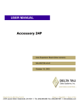
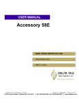
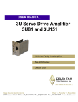
1
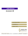
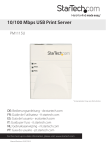
^1USER MANUAL
^2 AMP 1
^3 40W 4-Channel Linear Brush Motor
^4 3Ax-603489-xUxx
^5 August 22, 2006
Single Source Machine Control
Power // Flexibility // Ease of Use
21314 Lassen Street Chatsworth, CA 91311 // Tel. (818) 998-2095 Fax. (818) 998-7807 // www.deltatau.com
Copyright Information
© 2003 Delta Tau Data Systems, Inc. All rights reserved.
This document is furnished for the customers of Delta Tau Data Systems, Inc. Other uses are
unauthorized without written permission of Delta Tau Data Systems, Inc. Information contained in
this manual may be updated from time-to-time due to product improvements, etc., and may not
conform in every respect to former issues.
To report errors or inconsistencies, call or email:
Delta Tau Data Systems, Inc. Technical Support
Phone: (818) 717-5656
Fax: (818) 998-7807
Email: [email protected]
Website: http://www.deltatau.com
Operating Conditions
All Delta Tau Data Systems, Inc. motion controller products, accessories, and amplifiers contain
static sensitive components that can be damaged by incorrect handling. When installing or handling
Delta Tau Data Systems, Inc. products, avoid contact with highly insulated materials. Only
qualified personnel should be allowed to handle this equipment.
In the case of industrial applications, we expect our products to be protected from hazardous or
conductive materials and/or environments that could cause harm to the controller by damaging
components or causing electrical shorts. When our products are used in an industrial environment,
install them into an industrial electrical cabinet or industrial PC to protect them from excessive or
corrosive moisture, abnormal ambient temperatures, and conductive materials. If Delta Tau Data
Systems, Inc. products are exposed to hazardous or conductive materials and/or environments, we
cannot guarantee their operation.
REVISION HISTORY
REV.
1
DESCRIPTION
E-POINT JUMPER & AMP SPEC REVISIONS
DATE
CHG
APPVD
08/22/06
CP
R. UNADKAT
Amp 1
Table of Contents
INTRODUCTION ........................................................................................................................................ 1
Power Supply Considerations .................................................................................................................... 1
Selecting Current vs. Voltage Mode .......................................................................................................... 1
Maximum Current Output E-Point Jumpers.......................................................................................... 1
Amplifier-Enable/Fault Polarity Selection ............................................................................................ 2
Torque/Velocity Control ............................................................................................................................ 2
HARDWARE DESCRIPTION ................................................................................................................... 3
TB1: 8-Pin PMAC Interface Terminal Block ............................................................................................ 3
TB2: 13-Pin Motor Amplifier Output Terminal Block .............................................................................. 3
TB3: External Power Ground..................................................................................................................... 3
TB4: External Power.................................................................................................................................. 3
TB5: External Logic Power........................................................................................................................ 4
P1: 96 Pin Power Input Connector ............................................................................................................. 4
Amplifier Specifications ............................................................................................................................ 5
Power Stage Specifications.................................................................................................................... 5
Mechanical Specifications ..................................................................................................................... 5
Environmental ....................................................................................................................................... 5
Amplifier User Components Description................................................................................................... 5
Fuses...................................................................................................................................................... 5
LEDs...................................................................................................................................................... 5
Offset Pots ............................................................................................................................................. 6
SAMPLE WIRING DIAGRAM.................................................................................................................. 7
ANALOG AMPLIFIER BACKPLANE BOARD ..................................................................................... 9
Single Quad H-Bridge Amplifier Backplane Layout ................................................................................. 9
Dual Quad H-Bridge Amplifier Backplane Layout.................................................................................. 10
Table of Contents
i
Amp 1
INTRODUCTION
The Amp 1 Linear Amplifier is a 3U-size amplifier designed to drive small DC brushed type motors or
proportional hydraulic valve actuators. This amplifier provides four 40W continuous (60W intermittent)
linear amplifiers. The Amp 1 Linear Amplifier may be interfaced conveniently to the PMAC controller
via Acc-24E2A. The maximum bus voltage for this amplifier is 24VDC and the continuous rating for
each drive is 0.5A.
The amplifiers on this product will output a current or voltage that is proportional to the voltage input.
The amplifier can receive its logic power supply (_15V) from the 3U-power supply and the bus voltage is
supplied from a separate supply.
Power Supply Considerations
The Amp 1 Linear Amplifier requires a single power supply of +12V to +24V max. The current
requirement can vary depending on the load, but should not exceed 4A (1A per channel) continuous and
8A peak (2A per channel) for a one-second period. A slow blow 5A fuse is installed to protect the shunt
and a fast acting 8A fuse to protect the main bus.
If the amplifier is driven beyond its rated power, driver overheating may occur. In this event, the driver
will output a fault signal on the corresponding pin of Terminal Block 2 (TB2) and turn on the
corresponding red LED next to Terminal Block 1, TB1, shown in the Amplifier Layout Diagram.
Selecting Current vs. Voltage Mode
The Amp 1 Linear Amplifier can be configured in either current or voltage mode. This is configured by
setting the following E-point jumpers.
Maximum Current Output E-Point Jumpers
Each of the amplifiers has an E-point jumper that allows changing the transconductance factor of the
amplifier.
Jumper
E1A
E1B
E1A & E2
No jumper
Description
Channel 1 Setup
Jumper 1-2 Current Mode with gain of 0.2 A/V
Jumper 1-2 Current Mode with gain of 0.04 A/V
Jumper 1-2 Voltage Mode with gain of 1V in = 2.6V out
Jumper 1-2 Current Mode with gain of 0.02 A/V
Default
X
Channel 2 Setup
E3A
E3B
E3A & E4
No jumper
Jumper 1-2 Current Mode with gain of 0.2 A/V
Jumper 1-2 Current Mode with gain of 0.04 A/V
Jumper 1-2 Voltage Mode with gain of 1V in = 2.6V out
Jumper 1-2 Current Mode with gain of 0.02 A/V
X
Channel 3 Setup
E5A
E5B
E5A & E6
No jumper
Jumper 1-2 Current Mode with gain of 0.2 A/V
Jumper 1-2 Current Mode with gain of 0.04 A/V
Jumper 1-2 Voltage Mode with gain of 1V in = 2.6V out
Jumper 1-2 Current Mode with gain of 0.02 A/V
X
Channel 4 Setup
E7A
E7B
E7A & E8
No jumper
Introduction
Jumper 1-2 Current Mode with gain of 0.2 A/V
Jumper 1-2 Current Mode with gain of 0.04 A/V
Jumper 1-2 Voltage Mode with gain of 1V = 2.6V out
Jumper 1-2 Current Mode with gain of 0.02 A/V
X
1
Amp 1
Jumpers are provided to lower the current output rating either 200 or 400mA, for motors with smaller
current needs. Effectively, this cuts the amplifier transconductance factor in half, allowing use of the full
+10V from PMAC’s DAC outputs rather than scaling the system to output +2V via Ix69.
Note:
If the amplifier is driving a DC motor at high speeds, the current supply to the
motor may be reduced if the back EMF voltage of the motor is sufficiently large
(refer to the motor manufacture’s data sheet).
Amplifier-Enable/Fault Polarity Selection
The controller (PMAC or UMAC) should be configured for low-true amplifier-enable signals. A green
LED next to Terminal Block 1 (TB1) for each amplifier on the 3U linear amplifier is lit when the board is
receiving power and that amplifier is enabled.
Also, if the amplifier fault signal is fed back to PMAC, bit 23 (the most significant bit) of Ix25 (PMAC)
or bit 23 of Ix24 for Turbo PMAC should be set to zero for Low True fault input. The red LED for each
channel is lit when the amplifier faults (overheats).
Torque/Velocity Control
For direct torque or velocity control, the following I-variables may be adjusted as part of the motor
software setup (Example for PMAC2-Turbo):
Ixx00
Ixx02
Ixx03
Ixx04
Ixx24
Ixx25
Ixx69
Set to 1 to activate motor.
Motor xx Command Output Address. For example:
I102=$078003 to use DAC1 with motor 1.
Motor xx Position Loop Feedback Address. For
example: I103=$3501 to use Encoder 1.
Motor xx Velocity Loop Feedback Address. For
example: I104=$3501 to use Encoder 1.
Set motor xx Flag Mode Control. For example:
I124=$100001 to specify high true fault input.
Set motor xx Flag Address. For example:
I125=$078000 to specify channel 1 flags.
Set motor xx Output Command Limit.
Refer to the Turbo PMAC/PMAC2 Software Reference Manual for full descriptions of these I-variables.
2
Introduction
Amp 1
HARDWARE DESCRIPTION
There are six connectors on the QUAD H-Bridge Amplifier board:
• TB1: 8-Pin PMAC Interface Terminal Block
• TB2: 13-Pin Motor Amplifier Output Terminal Block
• TB3: External Power Ground
• TB4: External Bus Power
• TB5: External logic power
• P1: 96-Pin Power Input Connector
TB1: 8-Pin PMAC Interface Terminal Block
This terminal block provides the actual connection to the motors.
Pin
Symbol
Function
1
2
3
4
5
6
7
8
AMPOUT1
AMPOUT1/
AMPOUT2
AMPOUT2/
AMPOUT3
AMPOUT3/
AMPOUT4
AMPOUT4/
Output
Output
Output
Output
Output
Output
Output
Output
Description
First Motor + Lead
First Motor - Lead
Second Motor + Lead
Second Motor - Lead
Third Motor + Lead
Third Motor - Lead
Fourth Motor + Lead
Fourth Motor - Lead
TB2: 13-Pin Motor Amplifier Output Terminal Block
This connector brings in up to four analog command signals and amplifier-enable lines. It also sends the
amplifier fault signal back to the controller.
Pin
Symbol
Function
1
2
3
4
5
6
7
8
9
10
11
12
13
DAC1+
AENA1FAULT1DAC2
AENA2FAULT2AGND
DAC3
AENA3FAULT3DAC4
AENA4FAULT4-
Input
Input
Output
Input
Input
Output
Input
Input
Output
Input
Input
Output
Description
Notes
Command Signal 1
Amplifier Enable 1
Amplifier Fault 1
Command Signal 2
Amplifier Enable 2
Amplifier Fault 2
Analog Ground
Command Signal 3
Amplifier Enable 3
Amplifier Fault 3
Command Signal 4
Amplifier Enable 4
Amplifier Fault 4
Reference to AGND
Reference to AGND
Reference to AGND
Reference to AGND
Reference to AGND
Reference to AGND
Reference to AGND
Reference to AGND
Reference to AGND
Reference to AGND
Reference to AGND
Reference to AGND
TB3: External Power Ground
Pin
Symbol
Function
1
PGND
Input
Description
Bus power reference
TB4: External Power
Pin
Symbol
Function
1
A+24V
Input
Hardware Description
Description
Bus power reference
3
Amp 1
TB5: External Logic Power
Pin
Symbol
Function
1
2
3
4
AGND
A+15V
AGND
A-15V
Input/Output
Input
Input/Output
Input
Description
Reference for logic supply
For logic power (usually from backplane)
Reference for logic supply
For logic power (usually from backplane)
P1: 96 Pin Power Input Connector
4
Pin#
Row A
Row B
Row C
1
2
3
4
5
6
7
8
9
10
11
12
13
14
15
16
17
18
19
20
21
22
23
24
25
26
27
28
29
30
31
32
PGND
PGND
PGND
PGND
PGND
PGND
PGND
PGND
NC
+24V (bus)
+24V (bus)
+24V (bus)
+24V (bus)
+24V (bus)
+24V (bus)
+24V (bus)
+24V (bus)
NC
DB R+
DB R+
DB R+
DB R+
NC
DB RDB RDB RDB RNC
AGND
A+15V
AGND
A-15V
PGND
PGND
PGND
PGND
PGND
PGND
PGND
PGND
NC
+24V (bus)
+24V (bus)
+24V (bus)
+24V (bus)
+24V (bus)
+24V (bus)
+24V (bus)
+24V (bus)
NC
DB R+
DB R+
DB R+
DB R+
NC
DB RDB RDB RDB RNC
AGND
A+15V
AGND
A-15V
PGND
PGND
PGND
PGND
PGND
PGND
PGND
PGND
NC
+24V (bus)
+24V (bus)
+24V (bus)
+24V (bus)
+24V (bus)
+24V (bus)
+24V (bus)
+24V (bus)
NC
DB R+
DB R+
DB R+
DB R+
NC
DB RDB RDB RDB RNC
AGND
A+15V
AGND
A-15V
Hardware Description
Amp 1
Amplifier Specifications
Power Stage Specifications
Description
Specification
V+ input voltage
Logic power
Transconductance factor
Max continuous current
Peak current
Command input voltage
12V minimum, 24V maximum
15V @ 100mA, -15V @ 50mA
0.2 A/V, 0.04 A/V, or 0.02 A/V
4A (1A per channel)
8A (2A per channel)
+/- 10V
Mechanical Specifications
Size & Dimension
See Diagram
TB1 Connector
TB2 Connector
TB3 Connector
TB5 Connector
TB4 Connector
P1 Connector
8-pin Screw Terminal
13-pin Phoenix
1-pin Screw Terminal
1-pin Screw Terminal
4-pin Screw Terminal
96-pin 3U back plane
Environmental
Operating Temperature
0 C to 55 C (32 F to 135 F)
Storage temperature
Humidity
-12 C to 82 C (10 F to 180 F)
0% to 95%, non-condensing
Amplifier User Components Description
Fuses
Label
Type
F1
8A
Description
Fast Blow for BUS
LEDs
Hardware Description
Label
Function
LD1
LD2
LD3
LD4
LD5
LD6
LD7
LD8
LD10
Channel 1 Enable
Channel 1 Fault
Channel 2 Enable
Channel 2 Fault
Channel 3 Enable
Channel 3 Fault
Channel 4 Enable
Channel 4 Fault
Over Temperature Fault
5
Amp 1
Offset Pots
Name
A
B
C
D
6
Label
Function
R6
R46
R86
R126
Channel 1 Current Offset
Channel 2 Current Offset
Channel 3 Current Offset
Channel 4 Current Offset
Hardware Description
Amp 1
SAMPLE WIRING DIAGRAM
Sample Wiring Diagram
7
Amp 1
8
Sample Wiring Diagram
Amp 1
ANALOG AMPLIFIER BACKPLANE BOARD
The analog amplifier backplane board allows easy access to power the Quad H-Bridge amplifier units
when placed in the 3U racks. The amplifier backplane boards come in two options: single amplifier 2-slot
assemblies or dual amplifier 4-slot assemblies. The board itself has terminal screws for the external bus,
external shunt resistors, a Molex connector for the logic power, and another Molex connector for the
cooling fans.
Backplane Board
Part Number
Single Amplifier
Dual Amplifier
603490-10x
603470-10x
3U Slots used
2
4
Single Quad H-Bridge Amplifier Backplane Layout
Analog Amplifier Backplane Board
9
Amp 1
Dual Quad H-Bridge Amplifier Backplane Layout
10
Analog Amplifier Backplane Board