1
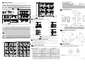
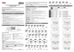
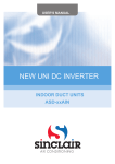
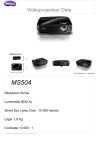
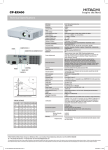
2006-12-08 4. Specification Power input Input voltage range Power consumption External power supply Display 5011646001-CTE1 Instruction Sheet Input signal Thank you very much for purchasing DELTA CTA series. Please read this instruction sheet before using your CTA series to ensure proper operation and please keep this instruction sheet handy for quick reference. Output 1 Output 2 ¾ DANGER! Caution! Electric Shock! ¾ When the power is on, DO NOT touch the AC terminals in case an electric shock may occur. ¾ Make sure the power is disconnected when you check the unit inside. Dielectric strength Vibration resistance Shock resistance Ambient temperature Storage temperature Altitude Ambient humidity Pollution degree ¾ CTA series is an OPEN-TYPE device. They are intended for installation completely within an overall panel and are for use in counting or timing application. If it will cause serious injury to workers or damage on other equipments when used in a dangerous environment, please make sure it is installed in an automatic safety protection device. 1. Precaution 1. Always use recommended solder-less terminals: Fork terminal with isolation (M3 screw, width 7.0mm), hole (diameter 3.2mm). Screw size: M3x6.5 (with 6.8x6.8 square washer). Recommended tightening torque: 0.4 N.m (4kgf.cm). 2 Applicable wire: solid/twisted wire of 2mm , 12AWG to 24 AWG. Please be sure to tighten them properly. 2. Prevent dust or metallic debris from falling into the device and cause malfunctions. 3. DO NOT modify or uninstall the device. 4. DO NOT use empty terminals. 5. Make sure the wires are correctly connected to proper terminals. 6. Keep away from high-voltage and high-frequency environment during installation in case of interference. 7. Prevent using the device in premises which contain: ․Dust or corrosive gas ․High humidity ․High radiation ․Vibration and shock 8. CTA series is an open-type device. Make sure to install it in an enclosure to prevent dust, humidity in case of an electric shock. 9. Please make sure the power cables and signal device are installed correctly before switching on the power; otherwise serious damage may occur.。 10. DO NOT touch the terminals or repair the device when the power is on; otherwise an electric shock may occur. 11. Please wait for one minute after the power is switched off to allow the capacitor to discharge and DO NOT touch the internal wiring within this period. 12. Use dry cloth to clean the device. DO NOT use acid or alkaline liquid to clean the device. 2. Display, Indicators and Keys 5. PV(Present Value) display Pause signal Output signal Clear signal t t Down Setup Timer function, (counting up or down) Select a function Select output mode of Timer MODE MODE Up 0 Down 0 Lock key Reset key Signal On Delay 2 Power signal Power signal Start signal Start signal Pause signal Pause signal Clear signal Clear signal Output signal Output signal SV SV Up Up 0 Mode and number shift key Setup the displayed unit of timer MODE Setup the pulse width of output 1 MODE Reset min. pulse width MODE Select input type (PNP or NPN) Signal On MODE Power signal Power signal Start signal Start signal Pause signal Pause signal Back to “select a function” MODE Clear signal Clear signal t Output signal Select counting modes Setup input mode of Counter MODE MODE Setup output mode of Counter (not dual output) MODE Select input type (PNP or NPN) Reset min. pulse width Setup dual output counting mode (dual output) MODE MODE Setup counting speed t MODE Setup pre-scale value MODE Setup the pulse width of output 1 Setup the pulse width of output 2 MODE MODE Tachometer Setup counting speed Setup the decimal point Down 0 0 Power On Delay Hold Power signal Power signal Start signal Start signal Pause signal Pause signal Clear signal Clear signal Output signal Output signal Setup pre-scale value MODE Select input type (PNP or NPN) Reset min. pulse width MODE Light on when reset signal is detected BATCH “Batch Counting Mode” in Counter and Tachometer function Light on when key-protected mode is enabled SET 1 2 SV1, SV2 display Light on when output is executing TAC Light on when Tachometer function is executing Hour, minute, second, unit of timer, displayed CNT Light on when Counter function is executing in Timer function TOTAL “Total Counting Mode” in Counter and TMR Light on when Timer function is executing Tachometer function Select a function MODE Setup Timer function, (counting up or down) MODE Key Operation Increase and decrease SV or change parameter settings. Left move 1 digit of the selected digit. The indicator of the selected digit will flash. Save the set parameters or switch among functions. Prevent settings from being changed. Key-protected mode still works after the power is switched off. Press LOCK to enter key-protected mode. In non-key-protected status, press LOCK to enter Lock 1. In Lock 1, press LOCK again to enter Lock 2. Press and at the same time to disable key-protected mode. (Lock 1) disables the functions of all keys. (Lock 2) allows users to change SV and functions of RESET remain. LOCK only functions in non-key-protected status. Clear and reset PV. MODE Modes: Operation Mode and Configuration Mode Operation When the power is on, the timer/counter/tachometer is in the operation mode. Press to change SV, or to make change on a desired digit. The indicator of the selected digit will flash. After the change is made, to save the setting. If SV or parameters are not changed, press once to switch between SET1 and press SET2. Configuration Press in operation mode for more than 3 seconds to enter configuration mode. Press once to switch among parameters. To return to operation mode, press for more than 3 seconds. MODE Setup output mode of timer Back to “select a function” MODE Select input type (PNP or NPN) MODE 6. Setup the displayed unit of timer Setup input mode of Counter MODE Reset min. pulse width MODE Setup output mode of Counter (not dual output) MODE Save data or not while switching off power MODE Setup counting speed MODE MODE Power signal Start signal Start signal Pause signal Pause signal Clear signal Clear signal Output signal Output signal Setup the decimal point MODE Setup the pulse width of output 2 t SV Up 0 0 SV SV Down 0 0 Repeat Cycle Hold Power signal Start signal Start signal Pause signal Pause signal Clear signal Clear signal Output signal Output signal SV SV1 Select counting up or counting down Setup the output time of timer, from 0 to 99.99 secs. 0= Hold output Setup output modes Up Down SV2 Up 0 0 SV1 SV2 SV Down 0 0 MODE MODE 3. Ordering Information CTA 1 2 3 4 5 6 n Product name CTA: Delta Counter/Timer/Tachometer A series q Preset stage 0: 2 preset stage o Panel size 4: 48mm x 48mm 1/16DIN r Communication 0: none p Output 2 0: NPN; 1: Relay s Power supply A: AC 100~240V Power signal Power signal A unit = 10ms. A unit = 0.1sec. A unit = 1 sec. A unit = 0.01 sec. A unit = 0.1 sec. A unit = 0.1 min. A unit = 1 min. A unit = 1 sec. A unit = 1 min. A unit = 1 hr. Max. counting = 9999.99 secs. Max. counting = 99999.9 secs. Max. counting = 999999 secs. Max. counting = 5999.99 secs. Max. counting = 59999.9 secs. Max. counting = 99999.9 mins. Max. counting = 999999 mins. Max. counting = 359999 secs (100hr) Max. counting = 35999999 secs (10000hr) Max. counting = 999999 hrs Signal Cumulate Repeat Cycle 2 MODE MODE RCYH timer output not set as 0 Timer output set as 0 Power signal MODE There are counting up/down modes, several counting units and output modes to choose from in timer function. Start signal Start signal Pause signal Pause signal Clear signal Clear signal Output signal Output signal SV1 Up SV2 Up 0 Down t SV Up MODE Timer Function Setup the counting unit of the timer. sec 0.01~9999.99 sec 0.1~99999.9 sec 1~999999 min,sec 0.01~9959.99 min,sec 0.1~99959.9 min 0.1~99999.9 min 1~999999 hr,min,sec 1~995959 hr,min 1~999959 hr 1~999999 timer output set as 0 Power signal Down MODE Setup pre-scale value Setup the pulse width of output 1 timer output not set as 0 SV Down MODE MODE Repeat Cycle SV 0 MODE Setup the delay time while switching on power t 0 Repeat Cycle ! Setup the average of input data t Up Up SV MODE Timer + Counter Mixed RST 1/2 K/P 1/2 OUT 1/2 HMS SV Down Down MODE MODE t 0 0 SV t Setup output mode of Tachometer t MODE Setup the decimal point MODE t SV Up Up t Output signal Power On Delay MODE Save data or not while switching off power MODE LCD Display and indicators 0 SV Down 0 t Back to “select a function” Up/Down key 0 Signal On Delay 1 SV Timer function indicator Counter function indicator Tachometer function indicator Special function indicator 0 SV SV SV Down Counter Select a function t SV SV Up t Output signal Signal Off Delay Select a function SV(Set Value) display Output 2 indicator Output 1 indicator RESET Pause signal SV Key protect 1 indicator LOCK Start signal 0 MODE Key protect 2 indicator Start signal Timer Back to “select a function” Reset 1 indicator Power signal Clear signal Parameters in Configuration Mode Reset 2 indicator MODE AC 100~240V, 50/60Hz 85% to 110%, rated voltage Less than 10VA 12Vdc ±10%, 100mA Double-line, 6-digit negative transmissive LCD display Non-voltage input (NPN): ON impedance 1K ohm max. ON residual voltage: 2V max. Voltage input (PNP): High level: 4.5 to 30Vdc, Low level: 0 to 2Vdc Relay: SPST max.250Vac, 5A (resistance load) Transistor: NPN open collector. When 100mA /30Vdc, residual voltage=1.5Vdc max. Relay: SPDT max.250Vac, 5A (resistance load) Transistor: NPN open collector. When 100mA /30Vdc, residual voltage=1.5Vdc max. 2000Vac 50/60 Hz for 1 minute Without damage: 10~55Hz, amplitude=0.75mm, 3 axes for 2 hours Without damage: drop 4 times, 300m/s2, 3 edges, 6 surfaces and 1 corner 0 oC to +50 oC -20 oC to +65 oC 2000m or less 35% to 85% RH (non-condensing) Degree 2 Power signal SV1 SV2 0 SV1 SV2 SV1 Down SV2 0 Signal Twin ON-Start 0 Signal Twin OFF-Start t 7. Up/Down A, B, C Output mode setting Counter functions include 1-stage counting, 2-stage counting, batch counting, total counting and dual counting. 1-stage 2-stage Batch S RESET 999999 SV2 SV1 Only 1 SV is allowed. See “output modes of counter”. 2 SVs, 2 PVs are allowed. See “output modes of counter”. Apart from the counting of PV and SV, when PV=SV, the batch counting adds 1 and clear PV as 0 for recounting till the batch counting equals batch SV. Total counting adds up all the counting values till they reach SV for output. CP1 and CP2 can be independent counters, but the counting speed can only reach 5kHz. CP1 and CP2 can execute addition or subtraction . Total Dual SW5 OFF ON OFF ON OFF ON OFF ON Input mode Counter Function 0 OUT1 OUT2 T RESET SW6 OFF OFF ON ON OFF OFF ON ON SW7 OFF OFF OFF OFF ON ON ON ON Displayed unit 0.01 sec 0.1 sec 1 sec min, 0.01 sec min, 0.1 sec 0.1 min Min hr, min, sec SV2 SW4 OFF ON OFF ON OFF OFF ON ON Counter F N C R Output Mode Configuration Timer Tachometer Signal ON Delay 1 Lo-Lo Signal ON Delay 2 Lo-Hi Signal OFF Delay Hi-Lo Signal ON Hi-Hi Table 1 SV1 Command counting up/down UD_A 11. OUT1 Input modes of counter Terminal Definition Input connections OUT2 Individual Quadrature Counting down Command SW3 999999 0 Counting up Table 2 D RESET 999999 SV2 SV1 0 Counting up Counting down CP1: Counter input H CP1 L CP2: Counter input prohibited A CP2 H L CP1: Counter input CP1 H L A Prohibit 4 OUT1 OUT2 CP2: Counter input prohibited A Save the data before power off n-1 Present Value 2 1 n-2 n-3 Pre-scale function n-4 0 0 Note: A has to be larger than width of min. Input signal CP1: Counter input prohibited H CP1 L A H CP2 L 0 Note: A has to be larger than width of min. Input signal CP2: Counter input CP1: Counter input prohibited CP1 H L A Prohibit A CP2 H L 5 Present Value 3 2 CP2: Counter input CP1 H L B A Prohibit 8. Quadrature input UD_C B B B CP2 H L n Present Value n-2 n-3 1 0 n-4 0 Note: A has to be larger than width of min. Input signal 0 Note: A has to be larger than width of min. Input signal 3 Present Value n-5 2 Output modes of counter 1 0 Note: OUT2 set value 0 B Tachometer Function 2 1 0 F When PV reaches SV, output is enabled but counting continues. Recounting starts after reset signal is over. Output 2 remains. N When PV reaches SV, output is enabled but counting stops. Recounting starts after reset signal is over. Output 2 remains. C When PV reaches SV, recounting executes automatically. Output 2 is pulse output. Output 1 remains till Output 2 is over. R When PV reaches SV, counting stops till Output 2 (pulse) is over for recounting. Output 1 remains till Output 2 is over. K When PV reaches SV, output is enabled but counting continues. Recounting starts after reset signal is over. P When PV reaches SV, output is enabled and recounting is automatically executed. But display of counting remains till Output 2 (pulse) is over. Q When PV reaches SV, output is enabled but the counting continues. Recounting starts after Output 2 (pulse) is over. A When PV reaches SV, output is enabled but the counting stops. Recounting starts and Output 2 (pulse) executes after reset signal is over. S When PV ≥ SV1, Output 1 is enabled. When PV ≥ SV2, Output 2 is enabled T When PV ≤ SV1, Output 1 is enabled. When PV ≥ SV2, Output 2 is enabled. D When SV=PV, output is enabled but counting continues. Addition and subtraction modes are valid. The time of Output 1 and Output 2 (pulse) can be setup separately, ranging from 0.01 to 99.99 secs. Recounting refers to counting up or addition/subtraction counting starting from 0 and counting down starting from SV. The counting range: -99999~999999. The counting will restart from 0 if the counting exceeds the range. Output mode setting F Down Measurement value OUT1 set value OUT1 set value OUT1 OUT1 Output mode setting RESET 999999 SV2 K Down Multi-function input pin OUT2 set value OUT2 set value Measurement value OUT1 set value OUT1 set value OUT1 OUT1 OUT2 OUT1 set value : OUT1 ON OUT2 set value : OUT2 ON Delay time after switching on the power Setup average value of input filter 9. (HI-HI) (HI-LO) Measurement value Measurement value Measurement value OUT1 set value : OUT1 ON OUT2 set value : OUT2 ON 0 T T T T T T T T T T OUT1 T T T T T T T T T OUT2 OUT2 P 999999 RESET SV2 SV1 SV1 Gate Reset1 Start Reset1 Timer + Counter CP1 Gate Reset1 Start Dimension & Panel Cutout OUT2 Measurement value Measurement value OUT1 set value : OUT1 ON OUT2 set value : OUT2 ON : The tachometer will start to run when the set delay time is due after the power is switched on. (Range of delay time: 0.1~99.9 secs.) : Range for obtaining average (n = 0 ~ 3). This parameter obtains the average of 2n input data for more stable output value. Only 1-stage counting in Counter function is available. Easy DIP Switch Setup Users can use DIP switch to setup parameters. When DIP is switched to ON, the corresponding parameters can only be read, not changed. 999999 SV2 Tachometer CP1 Timer + Counter Mixed Function 10. OUT1 RESET 12. Timer CTA4 series SV1 T 13. How to Mount Step-1. Insert the controller through the panel cutout. Step-2. Insert the mounting bracket into the mounting groove at the top and bottom of the controller and push the mounting bracket forward until the bracket stops at panel wall. Step-3. Insert and tighten screws on bracket to secure the controller in place. 0 0 T T T T T TT T T T T T T T T T TT T T OUT1 OUT1 SW OUT2 OUT2 Q RESET 999999 8 RESET 999999 SV2 SV2 SV1 SV1 0 7 0 T R Measurement value Measurement value OUT1 set value : OUT1 ON OUT2 set value : OUT2 ON ․ RCY2, SCON, STON, STOFF in output mode of Timer function ․ Command up/down, Individual up/down, quadrature counting in input mode, S, T, D in output mode of Counter function SV2 0 C OUT2 OUT2 Measurement value Counter CP1 CP2 Reset1 Reset2 Up/Down A, B, C RESET 999999 SV1 N (LO-HI) In Timer + Counter function, SV1, PV1 and Output 1 are for Timer; SV2, PV2 and Output2 are for Counter. DIP switch is disabled. All timer and counter functions remain except Input mode Up Up/Down A, B, C OUT2 set value Measurement value The output of SV can be 1-stage or 2-stage. When the output is set as 1-stage, Output 2 will be the same as the Output 1. The output modes include: F, N, C, R, K, P, Q, A, S, T, D Input mode (LO-LO) has to be larger than width of 1/2 min. input signal. : Up : When is set, the current PV will be saved. When is displayed, the PV will be cleared. : When conducting unit conversion, PV = PV x PreScale value, ranging from 0.001 to 99.999. Measuring Rotation speed: Measuring pulse width and determining current frequency Output methods: Lo-Lo, Lo-Hi, Hi-Lo, Hi-Hi n-1 4 CTA4 series A Prohibit CP2 H L n 3 Present Value Individual counting up/down UD_B T T T T T T T T T T T T OUT1 OUT1 OUT2 OUT2 A RESET T T T TT T T T 6 5 RESET 999999 999999 4 SV2 SV2 SV1 SV1 0 0 T OUT1 T T T T T TT T T T T OUT1 T T T T T T T T T 3 OUT2 OUT2 2 1 Counter Reset pulse width ON: 1ms, OFF: 20ms Input type ON: PNP OFF: NPN N/A Timer Reset pulse width ON: 1ms, OFF: 20ms Unit of Timer See Table 1 Unit of Timer See Table 1 Counting speed Unit of Timer ON: 10K CPS OFF: 30 CPS See Table 1 Output mode of counter Output mode of Timer See Table 2 See Table 2 Output mode of counter Output mode of Timer See Table 2 See Table 2 Input mode of counter Time counting up/down ON: counting down OFF: counting up ON: down OFF: up ON: Enable DIP ON: Enable DIP OFF: Disable DIP OFF: Disable DIP Tachometer Reset pulse width ON: 1ms, OFF: 20ms Input type ON: PNP OFF: NPN N/A Counting speed ON: 10KHz OFF: 30Hz Output mode of Tachometer See Table 2 Output mode of Tachometer See Table 2 N/A ON: Enable DIP OFF: Disable DIP Delta Electronics, Inc. 31-1 Shien Pan Road, Kuei Shan Industrial Park, Taoyuan Shien 33341, Taiwan, R.O.C. TEL: +886-3-362-6301 FAX: +886-3-362-7267 The content of this /instruction sheet may be revised without prior notice. Please consult our distributors or download the most updated version at http://www.delta.com.tw/industrialautomation