1
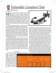
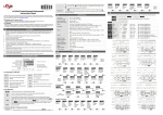
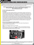
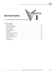
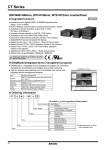
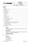
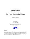
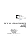
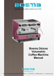
APPLICATION
EXAMPLES
CHAPTER
56
In This Chapter...
Counter Example 1 . . . . . . . . . . . . . . . . . . . . . . . . . . . . . . . . . . . . . . . . . . . . . . . . . .6-2
Counter Example 2 . . . . . . . . . . . . . . . . . . . . . . . . . . . . . . . . . . . . . . . . . . . . . . . . . .6-4
Timer Example . . . . . . . . . . . . . . . . . . . . . . . . . . . . . . . . . . . . . . . . . . . . . . . . . . . . . .6-5
Tach Example 1 . . . . . . . . . . . . . . . . . . . . . . . . . . . . . . . . . . . . . . . . . . . . . . . . . . . . .6-7
Tach Example 2 . . . . . . . . . . . . . . . . . . . . . . . . . . . . . . . . . . . . . . . . . . . . . . . . . . . . .6-8
w w w. a u to m at i o n d i re c t . c o m
Digital Counter / Timer / Tach User Manual, 1st Ed.
6-1
Counter Example 1:
1-Stage Counting (Stage)
Counting Up (UP)
Using the counter feature of the CTT to count the total number of pieces in a box to signal a conveyor to
advance to the next station.
Counting Input
Output 1
Reset
Count
Input Mode
Counting Up (UP)
With the input signal OFF at input CP2, each leading edge of the input signal at CP1 will increment the
count present value PV by 1. Turning ON the input signal at CP2 will prohibit the input signal at CP1 from
incrementing the PV. Or with the input signal ON at input CP1, each trailing edge of the input signal at
CP2 will increment the count present value PV by 1. Turning OFF the input signal at CP1 will prohibit the
input signal at CP2 from incrementing the PV.
Output Mode
Mode F (F)
When the count present value PV counts up to the count setting value SV both outputs 1 and 2 will turn
ON. The count PV will continue to increment with each input signal. The leading edge of a “reset” input
signal at RST1 will turn OFF both outputs, reset the count PV to 0, and prohibit an input signal from
incrementing the count PV. The trailing edge of the “reset” signal at RST1 enables
counting to begin.
6-2
Digital Counter / Timer / Tach User Manual, 1st Ed.
1 - 80 0 - 633 - 0405
Setting up the parameters in the counter for 1-Stage Counting:
To enter the page for parameter setting of the counter, press Ä for the main menu for more than 3 seconds. After
the setup is completed, press Ä for more than 3 seconds under any of the parameter page you are in and return
to the main menu.
Select functions: There are 4 modes in CTT, (left to right) timer, counter, tachometer and timer + counter.
–FunC
Ä
CntFun
Ä
C–inPt
Ä
C–otmd
Ä
or
time
Cont
or
taCh
or
or
–mix
Select counter functions: 1-stage counting, 2-stage counting, batch counting, total counting, dual counting.
or
sta6e1
or
sta6e2
batCh
or
or
total
or
dual
Select input modes: counting up, counting down, counting up/command down, counting up/counting down,
quadrature input.
or
––UP
down
or
ud–a
or
or
ud–b
or
ud–C
Select output modes: CTT offer 11 output modes, among which mode S, T and D are only valid with input modes
Ud_A, Ud_b and Ud_C.
or
F
or
n
or
C
or
r
or
k
or
q
or
a
or
s
or
t
or
d
or
p
Select counting speed: Maximum 10Kcps; others 5K, 1K, 200, 30 and 1cps.
C–Sped
Ä
t–out1
Ä
t–out2
Ä
–point
Ä
psCale
Ä
–pwers
Ä
–rtsr
Ä
inptlC
or
–10k
––5k
or
or
––1k
or
–200
or
––30
or
–––1
Pulse width of output 1: The default output time is 0.02 second. When the parameter is set to 0.00 second, the
output status will be maintained ON.
or
–002
or
–000
Pulse width of output 2: This paramter is adjustable according to different output modes selected. If the output mode is C,
the default output time will be 0.02 second, When the parameter is set to 0.00 second, the output status will be
maintained ON.
or
–002
–000
or
Set up the position of decimal point: 0 (no decimal point), 1 (one digit after decimal point), 2 (two digits after decimal
point), 3 (three digits after decimal point).
or
0
or
1
or
2
or
3
Set up pre-scale value: 1.000 (default 1:1) Range: 0.001 to 99.999
or
1000
Save the data while switching off the power: When SAVE is selected, the PV will be saved; when CLEAR is selected,
the PV will not be saved.
or
Clear
or
save
Set up minimum width of reset signal: Default = 20ms; 1ms is also selectable
or
––20
or
–––1
Select input signal types: NPN and PNP
or
–npn
or
–pnp
Ä
Back to Top
w w w. a u to m at i o n d i re c t . c o m
Digital Counter / Timer / Tach User Manual, 1st Ed.
6-3
Counter Example 2:
Example of cut to length operation
Using the counter function in CTT and acquires the feedback signal from the encoder for measuring the
actual distance traveled by the conveyor. When the set distance is reached, the output signal will enable
the knife for the cutting.
Counter
Encoder
Acquiring feedback
pulse signals form the
encoder for enagling the
cutting of the knife.
Motor
Select functions: There are 4 modes in CTT, (left to right) timer, counter, tachometer and timer + counter.
–FunC
Ä
CntFun
Ä
C–inPt
Ä
C–otmd
Ä
or
time
Cont
or
taCh
or
or
–mix
Select counter functions: 1-stage counting, 2-stage counting, batch counting, total counting, dual counting.
or
sta6e1
or
sta6e2
or
batCh
or
total
or
dual
Select input modes: counting up, counting down, command counting up/down, counting up/counting down,
quadrature input.
or
––UP
down
or
ud–a
or
or
ud–b
or
ud–C
Select output modes: CTT offer 11 output modes, among which mode S, T and D are only valid with input modes
Ud_A, Ud_b and Ud_C.
or
F
or
n
or
C
or
r
or
k
or
q
or
a
or
s
or
t
or
d
p
or
Select counting speed: Maximum 10Kcps; others 5K, 1K, 200, 30 and 1cps.
C–Sped
Ä
t–out1
Ä
t–out2
Ä
–point
Ä
psCale
Ä
–pwers
Ä
–rtsr
Ä
inptlC
or
–10k
or
––5k
or
––1k
or
–200
or
––30
or
–––1
Pulse width of output 1: The default output time is 0.02 second. When the parameter is set to 0.00 second, the
output status will be maintained ON.
or
–002
–000
or
Pulse width of output 2: This paramter is adjustable according to different output modes selected. If the output mode is C,
the default output time will be 0.02 second, When the parameter is set to 0.00 second, the output status will be
maintained ON.
or
–002
–000
or
Set up the position of decimal point: 0 (no decimal point), 1 (one digit after decimal point), 2 (two digits after decimal
point), 3 (three digits after decimal point).
or
0
or
1
or
2
or
3
Set up pre-scale value: 1.000 (default 1:1) Range: 0.001 to 99.999
or
1000
Save the data while switching off the power: When SAVE is selected, the PV will be saved; when CLEAR is selected,
the PV will not be saved.
or
Clear
or
save
Set up minimum width of reset signal: Default = 20ms; 1ms is also selectable
or
––20
or
–––1
Select input signal types: NPN and PNP
or
–npn
or
–pnp
Ä
Back to Top
6-4
Digital Counter / Timer / Tach User Manual, 1st Ed.
1 - 80 0 - 633 - 0405
Timer Example:
A basic Timer used to control a clamp time of a compression model press. When the operator signals the
mold is loaded with material by pressing the start button the hydraulic cylinder closes the press to make a
limit switch which starts the CTT timing. Upon completion of the timer cycle Output 1 is turned on and
the press is opened by the hydraulic cylinder.
Signal On Delay 1 (Sond1)
With power applied to the CTT, the leading edge of an input signal at START will begin the
timing period setting value SV timing up or down based on parameter (t modE) or by DIP Switch 2. At
the end of the timing period both outputs will turn ON momentarily for the time set in the output pulse
width parameter (tout1) or will be maintained ON if the output pulse width parameter (tout1) is set
to 0.00. The trailing edge of the “start” signal has no effect on the outputs or timing period. The leading
edge of an “reset” input signal at RST1 will turn OFF the outputs and reset the timing period. The "reset"
signal minimum pulse width is set by reset pulse width parameter
( rtSr ) or DIP Switch 8. The leading edge of an input “pause” signal at GATE will pause the
timing period after it has been started. The timing period will continue after the trailing edge of the
“pause” (Gate) signal. When power is removed, both outputs will turn OFF and the
timing period will be reset.
Limit
Switch
Starts
Timer
w w w. a u to m at i o n d i re c t . c o m
Reset
Output 1
Digital Counter / Timer / Tach User Manual, 1st Ed.
6-5
Setting Timer Parameters
To enter the page for parameter setting of the timer, press Ä in the main menu for more than 3 seconds. After the
setup is complete, press Ä for more than 3 seconds under any of the paramter page you are in and return to the main
menu.
Select funtions: There are 4 modes in CTT, (left to right) timer, counter, tachometer and timer + counter.
–funC
Ä
t–mode
Ä
time
or
or
Cont
taCH
or
or
–mix
Select timer mode: timing up and timing down
–up
or
or
down
Select output modes: There are 12 output modes in the timer. The user can choose the mode that best
meets the demand.
t–otmd
or
Ä
or
sond1
–rCy
or
or
sond2
rCyh
or
or
soffd
rCy2
or
or
–son
sCon
pond
ston
or
or
pondh
stoff
or
or
Select display unit: the min. unit 10ms to the max. unit hour are selectable.
t–unit
or
Ä
or
s–001
–m–1
or
or
s–01
hms–1
or
or
–s–1
hm–1
or
or
ms–001
–h–1
or
ms–01
or
m–01
Select pulse width of output 1: The default output time is 0.02 second. When the parameter is set to 0.00
second, the output status will be maintained ON.
t–out1
Ä
–rtsr
Ä
inptlC
or
–002
or
–000
Select min. width of reset signal: The defaul value is 20ms; can be set to 1ms.
or
––20
or
–––1
Select input signal types: NPN and PNP.
or
–npn
or
–pnp
Ä
Back to Top
6-6
Digital Counter / Timer / Tach User Manual, 1st Ed.
1 - 80 0 - 633 - 0405
Tach Example 1:
Using PSCALE to convert pulses into engineering units
The PSCALE feature of the CTT is very useful in converting the pulsed signal from an encoder or sensor into some
usable unit of measurement.
For example if one was to connect a proximity switch to the CTT to monitor the speed of a motor using a sensing gear
there is a simple calculation to convert the pulses from the sensor to Motor RPMs.
Using this formula you can calculate a PSCALE value to change a pulse signal into RPMs. First obtain the pulses per
revolution (ppr) or number of teeth on the sensing gear for example in the illustration below there are 38 teeth on the
gear or 38 ppr. If the gear is coupled directly to the motor this is all that is required to perform the calculation.
PSCALE = 60/ppr or 60/38
PSCALE = 1.579
With the PSCALE set to 1.579 for every 38 input cycles the CTT will display a value of 1.
Keypad set up of the parameters in the Tachometer:
Select functions: There are 4 modes in CTT, (left to right) timer, counter, tachometer and timer + counter.
–FunC
or
Ä
taotmd
Ä
or
or
or
or
or
2Lo1Lo
or
2Lo1Hi
or
2Hi1Lo
or
2Hi1Hi
–10k
––5k
or
or
––1k
or
–200
or
––30
or
–––1
0
or
1
or
2
or
3
1000
––00
Set up average value of the input filter: The average value is for making the present value detected by the tachometer
more stable. The setup range is 0 to 3 (1 = 2 data, 2 = 4 data, 3 = 8 data). For example, if you select “3”, the system will
average the 8 present values from the tachometer to make the present value displayed on the screen more stable.
Ä
–rtsr
Ä
–mix
Set up the delay time after switching on the power: 0.0 (default). The tachometer will start to run when the set delay
time is due after the power is switched on. Setup range: 0.1 to 99.9 seconds
St–taC
St–Av6
Ä
or
Set up pre-scale value: 1.000 (default 1:1) Range: 0.001 to 99.999
psCale
Ä
taCh
or
Set up the position of decimal point: 0 (no decimal point), 1 (one digit after decimal point), 2 (two digits after decimal
point), 3 (three digits after decimal point).
–point
Ä
Cont
or
Select rotation speed: Maximum 10Kcps; others 5K, 1K, 200, 30 and 1cps.
C–Sped
Ä
time
Select output modes: There are 4 output modes, 2Lo1Lo, 2Lo1Hi, 2Hi1Lo, and 2Hi1Hi, For example, when you select
2Hi1Lo, and assume the first set value is 100 (2Hi) and the second 50 (1Lo), the output value of the tachometer will be
below 100 (2Hi) and above 50 (1Lo) and CTT will not perform an output. If the set value exceeds the range, CTT will
perform an output.
or
0
or
1
or
2
or
3
Set up minimum width of reset signal: Default = 20ms; 1ms is also selectable.
or
––20
or
–––1
Select input signal types: NPN and PNP.
InptlC
or
–npn
or
–pnp
Ä
Back to Top
w w w. a u to m at i o n d i re c t . c o m
Digital Counter / Timer / Tach User Manual, 1st Ed.
6-7
Tach Example 2:
Convert an encoder signal into surface speed of a conveyor.
In order to monitor the speed of a part deliver conveyor belt an encoder with a surface contact measuring wheel is
attached to a conveyor where wheel will be in constant contact with the conveyor. Then the PSCALE is set to convert
the pulse signal of the encoder into feet/per/minute. Two variables are required, the Encoders pulses per revolution (ppr)
the diameter of the measuring wheel. For example when using an AutomationDirect TRD N100 RZWD encoder
which has 100 ppr in conjunction with a measuring wheel that is 6 inch in diameter the calculation would be as follows:
Wheel Diameter * or 6*3.1416 or 18.85” in circumference. 1 revolution of the wheel translates to
18.85” of linear motion.
PSCALE = wheel circumference / ppr or 18.85/100 = 0.1885 PSCALE.
Measuring Wheel
Select functions: There are 4 modes in CTT, (left to right) timer, counter, tachometer and timer + counter.
–FunC
or
or
or
or
or
St–Av6
Ä
–rtsr
Ä
2Lo1Lo
or
2Lo1Hi
or
2Hi1Lo
or
2Hi1Hi
–10k
––5k
or
or
––1k
or
–200
or
––30
or
–––1
0
or
1
or
2
or
3
1000
Set up the delay time after switching on the power: 0.0 (default). The tachometer will start to run when the set delay
time is due after the power is switched on. Setup range: 0.1 to 99.9 seconds
St–taC
Ä
–miy
Set up pre-scale value: 1.000 (default 1:1) Range: 0.001 to 99.999
psCale
Ä
or
Set up the position of decimal point: 0 (no decimal point), 1 (one digit after decimal point), 2 (two digits after decimal
point), 3 (three digits after decimal point).
–point
Ä
taCh
or
Select rotation speed: Maximum 10Kcps; others 5K, 1K, 200, 30 and 1cps.
C–Sped
Ä
Cont
or
Select output modes: There are 4 output modes, 2Lo1Lo, 2Lo1Hi, 2Hi1Lo, and 2Hi1Hi, For example, when you select
1Hi1Lo, and assume the first set value is 100 (2Hi) and the second 50 (1Lo), the output value of the tachometer will be
below 100 (2Hi) and above 50 (1Lo) and CTA will not perform an output. If the set value exceeds the range, CTT will
perform an output.
Ä
taotmd
Ä
time
or
––00
Set up average value of the input filter: The average value is for making the present value detected by the tachometer
more stable. The setup range is 0 to 3 (1 = 2 data, 2 = 4 data, 3 = 8 data). For example, if you select 3”, the system will
averagethe 8 present values from the tachometer to make the present value displayed on the screen more stable.
or
0
or
1
or
2
or
3
Set up minimum width of reset signal: Default = 20ms; 1ms is also selectable.
or
––20
or
–––1
Select input signal types: NPN and PNP.
InptlC
or
–npn
or
–pnp
Ä
Back to Top
6-8
Digital Counter / Timer / Tach User Manual, 1st Ed.
1 - 80 0 - 633 - 0405