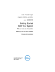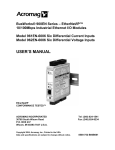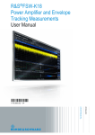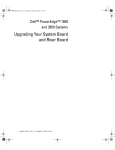
1
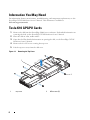
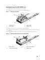
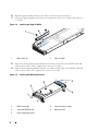
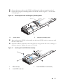
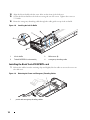
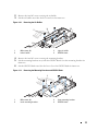
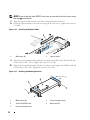
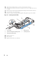
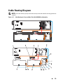
Dell PowerEdge C8220X
Tesla K10 GPGPU Card
Installation Guide
Regulatory Model: B06B
Regulatory Type: B06B001
Notes, Cautions, and Warnings
NOTE: A NOTE indicates important information that helps you make better use of
your computer.
CAUTION: A CAUTION indicates potential damage to hardware or loss of data if
instructions are not followed.
WARNING: A WARNING indicates a potential for property damage, personal
injury, or death.
____________________
Information in this publication is subject to change without notice.
© 2013 Dell Inc. All rights reserved.
Reproduction of these materials in any manner whatsoever without the written permission of Dell Inc.
is strictly forbidden.
Trademarks used in this text: Dell™, the DELL logo, and PowerEdge™ are trademarks of Dell Inc.
Intel is a registered trademark of Intel Corporation in the U.S. and other countries. NVIDIA and Tesla™
are trademarks and/or registered trademarks of NVIDIA Corporation.
Other trademarks and trade names may be used in this publication to refer to either the entities claiming
the marks and names or their products. Dell Inc. disclaims any proprietary interest in trademarks and
trade names other than its own.
Regulatory Model B06B
Regulatory Type: B06B001
2013 - 05
P/N 00VKC
Rev. A00
Contents
Important Safety Information .
Recommended Tools
. . . . . . . . . . . . . . . . . . . .
5
. . . . . . . . . . . . . . . . . . . . . . . . .
5
Information You May Need .
Tesla K10 GPGPU Cards
. . . . . . . . . . . . . . . . . . . . .
6
. . . . . . . . . . . . . . . . . . . . . . .
6
7
Installing the Front Tesla K10 GPGPU card
. . . . . . . .
Installing the Back Tesla K10 GPGPU card
. . . . . . .
10
. . . . . . . . . . . . . . . . . . . . . .
15
Cable Routing Diagram .
Contents
3
4
Contents
Important Safety Information
Observe the following safety precautions when installing NVIDIA Tesla K10 GPGPU cards in the
PowerEdge C8220X sled.
WARNING: Working on systems that are still connected to a power supply can be
extremely dangerous.
CAUTION: The sled must be operated with the cover installed to ensure proper cooling.
CAUTION: To ensure proper airflow in the PowerEdge C8000 server enclosure, if a sled
module is removed it should be immediately replaced with another sled or sled blank.
CAUTION: Operating the system for extended periods of time without a sled blank
installed can cause the PowerEdge C8000 server enclosure to overheat.
CAUTION: GPGPU cards can only be installed in the slots on the GPGPU card risers. Do
not attempt to install GPGPU cards directly into the riser connector on the system board.
NOTE: It is recommended that you always use a static mat and static strap while working on
components in the interior of the system.
To avoid injury to yourself or damage to your system, follow these guidelines:
•
Always disconnect the system from the power outlet whenever you are working inside the
system.
•
If possible, wear a grounded wrist strap when you are working inside the system.
Alternatively, discharge any static electricity by touching the bare metal chassis of the
system case, or the bare metal body of any other grounded appliance.
•
Hold electronic circuit boards by the edges only. Do not touch the components on the
board unless it is necessary to do so. Do not flex or stress the circuit board.
•
Leave all components inside the static-proof packaging until you are ready to use the
component for the installation.
•
Some cables have a connector with locking tabs; if you are disconnecting this type of cable,
press in on the locking tabs before you disconnect the cable. As you pull connectors apart,
keep them evenly aligned to avoid bending any connector pins. Also, before you connect a
cable, ensure that both connectors are correctly oriented and aligned.
Recommended Tools
You may need the following items to install NVIDIA Tesla K10 GPGPU cards in the PowerEdge
C8220X sled.
•
#1 or #2 Phillips screwdriver
•
Static mat
•
Static strap
5
Information You May Need
For information about system features, troubleshooting, and component replacement, see the
PowerEdge C8220X Hardware Owner’s Manual. This document is available at
dell.com/support/manuals.
Tesla K10 GPGPU Cards
1 Remove the sled from the PowerEdge C8000 server enclosure. For detailed information on
removing the sled, see the PowerEdge C8220X Hardware Owner’s Manual.
2 Place the sled on a flat, stable surface.
3 Open the sled. For detailed information on opening the sled, see the PowerEdge C8220X
Hardware Owner’s Manual.
4 Remove the five M3 screws securing the top cover.
5 Lift the top cover away from the sled cover.
Figure 1-1.
Removing the Top Cover
1
2
1
6
top cover
2
M3 screws (5)
Installing the Front Tesla K10 GPGPU card
1 Remove the four M3 screws securing the air baffles.
2 Lift the air baffles out of the sled cover and save for future use.
Figure 1-2.
Removing the Air Baffles
1
M3 screws (4)
2
right air baffle
3
left air baffle
4
GPGPU blank
3 Remove the four M3 screws securing the mounting brackets.
4 Lift the mounting brackets away from the GPGPU blank. Save the mounting brackets for
future use.
5 Lift the GPGPU blank out of the sled cover. Save the GPGPU blank for future use.
Figure 1-3.
Removing the Mounting Brackets and GPGPU Blank
1
M3 screws (4)
2
front mounting bracket
3
back mounting bracket
4
GPGPU blank
7
6 Align the right air baffle with the screw holes on the front of the sled cover.
7 Secure the right air baffle to the sled cover using the two M3 screws. Tighten the screws to
5.21 in-lbs.
Figure 1-4.
1
Installing the Right Air Baffle
M3 screws (2)
2
right air baffle
8 Align the front mounting bracket with the screw holes on the left of the GPGPU card and
secure with two M2.5 screws. Tighten the screws to 5.21 in-lbs.
9 Align the back mounting bracket with the screw holes on the right of the GPGPU card and
secure with two M3 screws. Tighten the screws to 5.21 in-lbs.
Figure 1-5.
8
Installing the Mounting Brackets
1
M2.5 screws (4)
2
front mounting bracket
3
Tesla K10 GPGPU card
4
M3 screws (2)
5
back mounting bracket
10 Connect the power cables to the GPGPU card. Ensure the cables are properly attached.
11 Connect the emergency throttling cable to the GPGPU card. See Figure 1-17 for the cable
routing diagram.
Figure 1-6.
1, 2
Connecting the Power and Emergency Throttling Cables
power cables
3
emergency throttling cable
12 Align and insert the GPGPU card assembly into the front GPGPU card riser connector until
the card is fully seated.
13 Secure the GPGPU card to the front of the sled cover using the four M3 screws, working in a
clockwise sequence. Tighten the screws to 5.21 in-lbs.
Figure 1-7.
Installing the Front GPGPU Card Assembly
1
M3 screws (4)
3
front GPGPU card riser
2
Tesla K10 GPGPU card assembly
9
14 Align the left air baffle with the screw holes on the front of the sled cover.
15 Secure the left air baffle to the sled cover using the two M3 screws. Tighten the screws to
5.21 in-lbs.
16 Route the emergency throttling cable through the cable guide on top of the air baffle.
Figure 1-8.
Installing the Left Air Baffle
1
left air baffle
2
M3 screws (2)
3
Tesla K10 GPGPU card assembly
4
emergency throttling cable
Installing the Back Tesla K10 GPGPU card
1 Release the cables from the retaining clips and slightly lift the cables to access the screws on
the sled cover.
Figure 1-9.
Releasing the Power and Emergency Throttling Cables
1
1
10
power and emergency throttling cables
2 Remove the four M3 screws securing the air baffles.
3 Lift the air baffles out of the sled cover and save for future use.
Figure 1-10.
Removing the Air Baffles
1
M3 screws (4)
2
right air baffle
3
left air baffle
4
GPGPU blank
4 Remove the four M3 screws securing the mounting brackets.
5 Lift the mounting brackets away from the GPGPU blank. Save the mounting brackets for
future use.
6 Lift the GPGPU blank out of the sled cover. Save the GPGPU blank for future use.
Figure 1-11.
Removing the Mounting Brackets and GPGPU Blank
2
3
1
4
1
M3 screws (4)
2
front mounting bracket
3
back mounting bracket
4
GPGPU blank
11
NOTE: Ensure that the back GPGPU card riser is secured to the sled cover using
the type B screw holes.
7 Align the right air baffle with the screw holes on the back of the sled cover.
8 Secure the right air baffle to the sled cover using the two M3 screws. Tighten the screws to
5.21 in-lb.
Figure 1-12.
1
Installing the Right Air Baffle
M3 screws (2)
2
right air baffle
9 Align the front mounting bracket with the screw holes on the left of the GPGPU card and
secure with two M2.5 screws. Tighten the screws to 5.21 in-lb.
10 Align the back mounting bracket with the screw holes on the right of the GPGPU card and
secure with two M3 screws. Tighten the screws to 5.21 in-lb.
Figure 1-13.
12
Installing the Mounting Brackets
1
M2.5 screws (4)
2
front mounting bracket
3
Tesla K10 GPGPU card
4
M3 screws (2)
5
back mounting bracket
11 Connect the power cables to the GPGPU card. Ensure the cables are properly attached.
12 Connect the emergency throttling cable to the GPGPU card.
Figure 1-14.
1, 2
Connecting the Power and Emergency Throttling Cables
power cables
3
emergency throttling cable
13 Align and insert the GPGPU card assembly into the back GPGPU card riser connector until
the card is fully seated.
14 Secure the GPGPU card to the back of the sled cover using the four M3 screws, working in a
clockwise sequence. Tighten the screws to 5.21 in-lb.
Figure 1-15.
Installing the Back GPGPU Card Assembly
1
M3 screws (4)
3
back GPGPU card riser
2
Tesla K10 GPGPU card assembly
13
15 Align the left air baffle with the screw holes on the back of the sled cover.
16 Secure the left air baffle to the sled cover using the two M3 screws. Tighten the screws to
5.21 in-lb.
17 Route the power and emergency throttling cables along the inside wall of the sled cover.
18 Secure the cables to the retaining clips.
19 Route the emergency throttling cable through the cable guide on top of the air baffle.
Figure 1-16.
Installing the Left Air Baffle
1
left air baffle
2
M3 screws (2)
3
power and emergency throttling cables
4
retaining clips (3)
5
emergency throttling cable
20 Replace the top cover.
21 Close the sled.
22 Replace the sled in the server enclosure.
14
Cable Routing Diagram
NOTE: Route the cables properly inside the sled to prevent the cables from being pinched or
crimped.
Figure 1-17.
Cable Routing for Front and Back Tesla K10 GPGPU Card Assembly
15
16
1
power connector on front GPGPU card
riser
2
power connector on back GPGPU card
riser
3
twin axial cable on back GPGPU
card riser
4
twin axial cable connector on system
board
5
power/emergency throttling connector
on node power distribution board (NPDB)
6
power/emergency throttling connector
on NPDB
7
power connector on NPDB
8
power connector on NPDB
9
power connector on NPDB
10
power connector on NPDB
11
power connector on NPDB
12
power connector on back Tesla K10
GPGPU card
13
power connector on back Tesla K10
GPGPU card
14
power/emergency throttling connector
on back Tesla K10 GPGPU card
15
power connector on front Tesla K10
GPGPU card
16
power connector on front Tesla K10
GPGPU card
17
power/emergency throttling connector on
front Tesla K10 GPGPU card