1
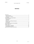
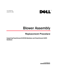
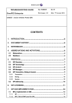
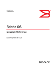
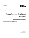
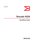
53-1001806-01
January 31, 2010
Control Processor Blade
(CP8)
Replacement Procedure
Supporting Fabric OS v6.0.0 through v6.3.x (as compatible with supported
hardware)
Supporting PowerConnect B-DCX-4S and PowerConnect B-DCX Backbone
53-1001806-01
*53-1001806-01*
Notes, Cautions, and Warnings
NOTE
A NOTE indicates important information that helps you make better use of your computer.
CAUTION
See the safety and regulatory information that shipped with your system. For additional regulatory
information, see the Regulatory Compliance Homepage on www.dell.com at the following location:
www.dell.com/regulatory_compliance.
CAUTION
A CAUTION indicates potential damage to hardware or loss of data if instructions are not followed.
DANGER
A DANGER indicates a potential for property damage, personal injury, or death.
____________________
Information in this document is subject to change without notice.
© 2009 Dell Inc. All rights reserved.
Reproduction of these materials in any manner whatsoever without the written permission of Dell Inc. is strictly forbidden.
Trademarks used in this text: Dell, the DELL logo, Inspiron, Dell Precision, Dimension, OptiPlex, Latitude, PowerEdge, PowerVault, PowerApp, Dell
OpenManage and the YOURS IS HERE logo are trademarks of Dell Inc.; Intel, Pentium, and Celeron are registered trademarks of Intel Corporation
in the U.S. and other countries; Microsoft, Windows, Windows Server, MS-DOS and Windows Vista are either trademarks or registered trademarks
of Microsoft Corporation in the United States and/or other countries.
Other trademarks and trade names may be used in this document to refer to either the entities claiming the marks and names or their products.
Dell Inc. disclaims any proprietary interest in trademarks and trade names other than its own.
Regulatory Model Codes: Brocade DCX-4S, Brocade DCX
2
Control Processor Blade (CP8) Replacement Procedure
53-1001806-01
In this guide
• Introduction. . . . . . . . . . . . . . . . . . . . . . . . . . . . . . . . . . . . . . . . . . . . . . . . . . . .
• Time and items required . . . . . . . . . . . . . . . . . . . . . . . . . . . . . . . . . . . . . . . . .
• Verifying the necessity of replacement . . . . . . . . . . . . . . . . . . . . . . . . . . . . . .
• Recording critical backbone information . . . . . . . . . . . . . . . . . . . . . . . . . . . .
• Removing a control processor blade (CP8) . . . . . . . . . . . . . . . . . . . . . . . . . .
• Replacing a control processor blade (CP8) . . . . . . . . . . . . . . . . . . . . . . . . . .
• Verifying operation of the new CP blade . . . . . . . . . . . . . . . . . . . . . . . . . . . . .
3
3
3
4
6
7
8
Introduction
This document describes how to remove and replace a control processor (CP8) blade. Each PowerConnect B-DCX-4S
and PowerConnect B-DCX has two CP8 blades. In the DCX-4S they are located in slots 4 and 5. In the DCX they are
located in slots 6 and 7.
NOTE
If the new CP blade does not have the same firmware as the active CP blade, the new blade must be upgraded to the
same firmware version.
Time and items required
The replacement procedure for the CP blade takes approximately 30 minutes. The following items are required for
the CP blade replacement:
•
•
•
•
•
•
ESD (electrostatic discharge) grounding strap
Workstation computer
Serial cable
IP address of an FTP server for backing up the backbone configuration
Phillips #2 screwdriver
Replacement CP8 blade.
Verifying the necessity of replacement
Confirm that you need to replace the CP blade. The following events might indicate that a CP blade is faulty:
•
•
•
•
•
•
The status LED on the CP blade is lit steady amber, or the power LED is not lit.
The CP blade does not respond to Telnet commands, or the serial console is not available.
The slotShow command does not show that the CP blade is enabled.
The haShow command indicates an error.
The clock is inaccurate, or the CP blade does not boot up or shut down normally.
Any of the following messages display in the error log:
Control Processor Blade (CP8) Replacement Procedure
53-1001806-01
3
•
•
•
•
•
•
•
•
“Slot unknown” message relating to a CP slot
CP blade errors or I2C timeouts
FRU: FRU_FAULTY messages for a CP blade
Configuration loader messages or “Sys PCI config” messages
Generic system driver messages (“FABSYS”)
Platform system driver messages (“Platform”)
EM messages that indicate a problem with a CP blade
Function fail messages for the CP master
For more information about error messages, refer to the Fabric OS Message Reference.
Recording critical backbone information
Back up the backbone configuration before you replace a CP blade. Refer to the Fabric OS Administrator’s Guide for
backup information.
ATTENTION
The instructions below reference specific slot numbers. these numbers will be different between the PowerConnect
B-DCX-4S and PowerConnect B-DCX.
1. Log in to the functioning CP blade as admin, using the serial console connection.
2. Type haShow to determine which CP blade is active:
swDir:admin> haShow
Local CP (Slot 7, CP1) : Active
Remote CP (Slot 6, CP0) : Standby, Healthy
HA Enabled, Heartbeat Up, HA State Synchronized
3. If the functioning CP blade is performing as the active CP blade, go to step 4. If the faulty CP blade is performing
as the active CP blade, fail over the blades:
a.
Log in to the faulty CP blade as admin, using a serial console connection.
If you connect successfully to the faulty CP, continue to step b.
If you cannot connect to the faulty CP, remove the faulty CP blade for repair as follows:
• Turn the CP blade off and notify the backbone of a hot swap request by sliding the slider switch in the
top ejector down to the off position (Figure 1).
• Wait until the active CP LED on the functioning CP blade is lit. Remove the faulty CP blade.
b.
Type haFailover. The functioning CP blade becomes the active CP blade.
c.
Wait until the status LED on the functioning CP blade is no longer lit.
d.
Type haShow from the functioning CP blade (the new active CP blade) to verify the failover.
Depending on the failure mode of the faulty CP blade, the haShow output may not show the “HA State
Synchronized” message but may indicate that the system is in non-redundant mode.
4
Control Processor Blade (CP8) Replacement Procedure
53-1001806-01
This is an example of failing over a CP blade:
Fabric OS (cp1)
cp1 login: admin
Password:
swDir:admin> hashow
Local CP (Slot 7, CP1): Active
Remote CP (Slot 6, CP0): Standby, Healthy
HA enabled, Heartbeat Up, HA State synchronized
swDir:admin> hafailover
Local CP (Slot 7, CP1): Active
Remote CP (Slot 6, CP0): Standby, Healthy
HA enabled, Heartbeat Up, HA State synchronized
Warning: This command is being run on a redundant control
processor(CP) system. If the above status does not indicate
'HA State synchronized', then the CPs are not synchronized
and this operation will cause the active CP to reset. This
will cause disruption to devices attached to both switch 0
and switch 1 and will require that existing Telnet sessions
be restarted. To reboot a single logical switch on this
system, use the switchreboot command while logged in to
that logical switch.
Are you sure you want to fail over to the standby CP [y/n]?
swDir:admin> haShow
Local CP (Slot 7, CP1) : Standby, Healthy
Remote CP (Slot 6, CP0) : Active
HA Enabled, Heartbeat Up, HA State Synchronized
4. Type firmwareShow to note the firmware version of the active CP blade.
5. Type haDisable from the active CP blade to prevent failover or communication between the CP blades during the
replacement.
6. Logged into the active CP, use the configUpload command to upload the backbone configuration to a specified
FTP server. Enter information at the prompts.
NOTE
For FOS 6.2.0 and above, the format of the command will look different from the example below. See the Fabric
OS Command Reference Manual and the Fabric OS Administrator’s Guide for more information about the
command.
This is a sample of backing up the configuration files:
swDir:admin> configUpload
Protocol (scp or ftp) [ftp]: ftp
Server Name or IP Address [host]: 123.456.78.90
User Name [None]: user
File Name [config.txt]: config.txt
Password: xxxxxxxx
upload complete
Once the upload is complete, stay logged in and move on to “Removing a control processor blade (CP8).”
Control Processor Blade (CP8) Replacement Procedure
53-1001806-01
5
Removing a control processor blade (CP8)
The PowerConnect B-DCX continues to operate while a CP blade is being replaced if the redundant CP blade is active
and a failover does not occur. You can prevent failover by entering the haDisable command.
ATTENTION
The instructions below refer to the top and bottom of each blade in the vertical orientation as used in the
PowerConnect B-DCX. For the PowerConnect B-DCX-4S, because the blades are horizontally oriented, top should be
read as left and bottom should be read as right.
ATTENTION
Follow ESD precautions (see “ESD Precautions” in your chassis’ hardware reference manual).
NOTE
The CP8 blade is compatible only with the PowerConnect B-DCX-4S Backbone and the PowerConnect B-DCX
Backbone.
1. Remove the chassis door (see the Chassis Door Replacement Procedure for your chassis).
2. Power off the faulty blade by sliding the slider switch in the top ejector down to the off position (Figure 1).
3. Disconnect all cables from the faulty (standby) CP.
4. Unscrew the thumb screw from both ejectors using the Phillips screwdriver.
5. Lever open both ejector handles simultaneously to approximately 45 degrees and pull the CP blade out of the
chassis (Figure 1 and Figure 2).
FIGURE 1
6
Control processor blade (CP8) in a DCX chassis
Control Processor Blade (CP8) Replacement Procedure
53-1001806-01
FIGURE 2
Control processor blade (CP8) in a DCX-4S chassis
Replacing a control processor blade (CP8)
ATTENTION
The instructions below refer to the top and bottom of each blade in the vertical orientation as used in the
PowerConnect B-DCX. For the PowerConnect B-DCX-4S, because the blades are horizontally oriented, top should be
read as left and bottom should be read as right.
ATTENTION
Follow ESD precautions (see “ESD Precautions” in your chassis’ hardware reference manual).
CAUTION
Use the same version of Fabric OS on both CP blades. Using different versions is not supported and
might cause malfunctioning. If the replacement CP blade has a different version of Fabric OS, bring both
blades to the same firmware version.
1. Open the ejector handles to approximately 45 degrees. For the DCX, orient the CP blade so that the handles are
toward you and the flat metal side is on your left. For the DCX-4S, the flat metal side should be on the bottom.
2. Align the flat metal side of the CP blade inside the lower and upper blade guides in the slot. Slide the CP blade
into the slot until it is firmly seated.
3. Tighten the thumb screw inside each handle using the Phillips screwdriver.
4. Turn the CP blade on by sliding the ON/OFF switch in the top handle up, to cover the thumb screw.
5. Verify that the power LED is green. If not, ensure that the CP blade has power and is firmly seated and that the
ejectors are in the locked position.
6. Connect the cables to the new CP blade.
Control Processor Blade (CP8) Replacement Procedure
53-1001806-01
7
7.
Verify the installation (“Verifying operation of the new CP blade”).
8. Replace the chassis door (see the Chassis Door Replacement Procedure for your chassis).
9. Remain logged in to the active CP and continue to “Verifying operation of the new CP blade.”
Verifying operation of the new CP blade
ATTENTION
The instructions below reference specific slot numbers. these numbers will be different between the PowerConnect
B-DCX-4S and PowerConnect B-DCX.
To verify that boot and POST are complete on the new CP blade and that the CP blade has achieved failover
redundancy, perform the following steps.
1. Type slotShow. The command output shows the new CP blade as “enabled”:
rsl8-st03-dcx-1:admin> slotShow
Slot
Blade Type
ID
Status
--------------------------------1
2
3
4
5
6
7
8
9
10
11
12
SW
SW
SW
SW
CR
CP
CP
CR
SW
SW
SW
SW
BLADE
BLADE
BLADE
BLADE
BLADE
BLADE
BLADE
BLADE
BLADE
BLADE
BLADE
BLADE
16
16
16
16
17
18
18
17
16
16
16
16
ENABLED
ENABLED
ENABLED
ENABLED
ENABLED
ENABLED
ENABLED
ENABLED
ENABLED
ENABLED
ENABLED
ENABLED
rsl8-st03-dcx-1:admin>
2. Determine the version by typing firmwareShow.
This example shows sample output for the firmwareShow command:
rsl8-st03-dcx-1:admin> firmwareShow
Slot Name
Appl
Primary/Secondary Versions
Status
-------------------------------------------------------------------------2 FS8-18
FOS
v6.1.0
v6.1.0
4 FR4-18i
FOS
v6.1.0
v6.1.0
6 CP0
FOS
v6.1.0
ACTIVE *
v6.1.0
Co-FOS
v6.1.0
v6.1.0
7 CP1
FOS
v6.1.0
STANDBY
v6.1.0
Co-FOS
v6.1.0
v6.1.0
8
Control Processor Blade (CP8) Replacement Procedure
53-1001806-01
10
FA4-18
FOS
SAS
12
FR4-18i
FOS
v6.1.0
v6.1.0
v3.1.1
v3.1.1
v6.1.0
v6.1.0
rsl8-st03-dcx-1:admin>
3. If the firmware versions for both CP blades are the same, skip to step 11.
4. If the firmware version on the replacement blade does not match that on the active CP blade a warning
message appears with the results of the firmwareshow command. You must bring the replacement blade to the
same firmware level as the active blade using the firmwareDownload -s command to bring it up to the proper
level.Complete the following steps beginning with step 5.
NOTE
The DCX-4S requires FOS 6.2.0 or later to be recognized. If the firmware on the replacement blade is earlier
than 6.2.0. it must be brought up to the version on the active CP blade, which must be at least v6.2.0.
5. Log out of the active CP blade and log in to the standby CP blade.
6. Type firmwareDownload -s to download the firmware to the standby CP blade. The -s option also disables the
autoreboot, so you will have to manually issue a reboot after the download finishes in order to initiate
firmwarecommit. Enter all requested information (use default values).
rsl8-st03-dcx-1:admin> firmwaredownload -s
Server Name or IP Address: 192.168.100.1
User Name: user
File Name: /software/v6.1.0/release.plist
Password: ********
Do Auto-Commit after Reboot [Y]:
Reboot system after download [N]:
Firmwaredownload has started.
2007/07/03-14:59:21, [SULB-1001], 923,, WARNING, Brocade DCX, Firmwaredownload command has
started.
Start to install packages......
dir
##################################################
ldconfig
##################################################
glibc
##################################################
bash
##################################################
readline
##################################################
terminfo
##################################################
termcap
##################################################
setup
##################################################
<output truncated>
tz
##################################################
mtracer-tool
##################################################
lkcd
##################################################
sysstat
##################################################
Removing unneeded files, please wait ...
Finished removing unneeded files.
All packages have been downloaded successfully.
Firmwaredownload has completed successfully.
2007/07/03-15:05:56, [SULB-1002], 924,, INFO, Brocade DCX, Firmwaredownload command has
completed successfully.
Control Processor Blade (CP8) Replacement Procedure
53-1001806-01
9
7.
Type firmwareDownloadStatus to verify that the firmware has been updated.
8. Ensure that you are still logged in to the standby CP blade (the blade for which you just changed the firmware
level) and type reboot. The reboot of the standby CP will initiate a firmwarecommit to the secondary partition
and log you out.
9. Log back in to standby CP blade and type firmwaredDownloadStatus on the standby CP blade to validate a
successful commit. This may take 10 minutes.
10. Log out of the standby CP blade and log in to the active CP blade.
11. Type haEnable to reenable HA on the active CP blade.
NOTE
For FOS 6.3.0 and later, haEnable will cause the standby CP blade to reboot. Wait until the power cycles and the
POST completes before moving to the next step.
12. Type haShow and verify that the command output includes “HA Enabled Heartbeat Up”. If not, reenter the
command until you have verified that redundancy is achieved.
13. Type version or firmwareShow to verify that the firmware version has been updated.
14. Pack the faulty CP blade in the packaging provided with the new CP blade, and contact the switch supplier to
determine the return procedure.
15. Replace the chassis door (see the Chassis Door Replacement Procedure for your chassis).
10
Control Processor Blade (CP8) Replacement Procedure
53-1001806-01