1
Installing and Maintaining
the E1200i System
Notes, Cautions, and Warnings
NOTE: A NOTE indicates important information that helps you make better use of your computer.
CAUTION: A CAUTION indicates potential damage to hardware or loss of data if instructions are not
followed.
WARNING: A WARNING indicates a potential for property damage, personal injury, or death.
Information in this publication is subject to change without notice.
© 2010 Dell Force10. All rights reserved.
Reproduction of these materials in any manner whatsoever without the written permission of Dell Inc. is strictly forbidden.
Trademarks used in this text: Dell™, the DELL logo, Dell Precision™, OptiPlex™, Latitude™, PowerEdge™, PowerVault™,
PowerConnect™, OpenManage™, EqualLogic™, KACE™, FlexAddress™ and Vostro™ are trademarks of Dell Inc. Intel®, Pentium®,
Xeon®, Core™ and Celeron® are registered trademarks of Intel Corporation in the U.S. and other countries. AMD® is a registered trademark
and AMD Opteron™, AMD Phenom™, and AMD Sempron™ are trademarks of Advanced Micro Devices, Inc. Microsoft®, Windows®,
Windows Server®, MS-DOS® and Windows Vista® are either trademarks or registered trademarks of Microsoft Corporation in the United
States and/or other countries. Red Hat Enterprise Linux® and Enterprise Linux® are registered trademarks of Red Hat, Inc. in the United States
and/or other countries. Novell® is a registered trademark and SUSE ™ is a trademark of Novell Inc. in the United States and other countries.
Oracle® is a registered trademark of Oracle Corporation and/or its affiliates. Citrix®, Xen®, XenServer® and XenMotion® are either registered
trademarks or trademarks of Citrix Systems, Inc. in the United States and/or other countries. VMware®, Virtual SMP®, vMotion®, vCenter®,
and vSphere® are registered trademarks or trademarks of VMWare, Inc. in the United States or other countries.
Other trademarks and trade names may be used in this publication to refer to either the entities claiming the marks and names or their products.
Dell Inc. disclaims any proprietary interest in trademarks and trade names other than its own.
November 2011
P/N 100-00056-03
Contents
1 About This Guide
Information Symbols and Warnings . . . . . . . . . . . . . . . . . . . . . . . . . . . . . . . . . . . . . . 7
Related Publications . . . . . . . . . . . . . . . . . . . . . . . . . . . . . . . . . . . . . . . . . . . . . . . . . . 8
2 The E1200 System
Operating Overview . . . . . . . . . . . . . . . . . . . . . . . . . . . . . . . . . . . . . . . . . . . . . . . . . . 9
3 Site Preparation
Site Selection Criteria . . . . . . . . . . . . . . . . . . . . . . . . . . . . . . . . . . . . . . . . . . . . . . . . 15
Rack Mounting . . . . . . . . . . . . . . . . . . . . . . . . . . . . . . . . . . . . . . . . . . . . . . . . . . . . . 16
Cabinet Placement . . . . . . . . . . . . . . . . . . . . . . . . . . . . . . . . . . . . . . . . . . . . . . . . . . 16
Power . . . . . . . . . . . . . . . . . . . . . . . . . . . . . . . . . . . . . . . . . . . . . . . . . . . . . . . . . . . . 16
Fans and Airflow . . . . . . . . . . . . . . . . . . . . . . . . . . . . . . . . . . . . . . . . . . . . . . . . . . . . 17
Storing Components . . . . . . . . . . . . . . . . . . . . . . . . . . . . . . . . . . . . . . . . . . . . . . . . . 17
4 Installing the AC Chassis
Unpacking the E1200 System. . . . . . . . . . . . . . . . . . . . . . . . . . . . . . . . . . . . . . . . . . 19
Installing the Equipment Rack Shelf Bar. . . . . . . . . . . . . . . . . . . . . . . . . . . . . . . . . . 19
Standard Front Chassis Mounting. . . . . . . . . . . . . . . . . . . . . . . . . . . . . . . . . . . . . . . 20
Installing the Chassis into an Equipment Cabinet. . . . . . . . . . . . . . . . . . . . . . . . . . . 21
5 Installing the DC Chassis
Unpacking the E1200 System. . . . . . . . . . . . . . . . . . . . . . . . . . . . . . . . . . . . . . . . . . 23
Installing the Equipment Rack Shelf Bar. . . . . . . . . . . . . . . . . . . . . . . . . . . . . . . . . . 23
Standard Front Chassis Mounting. . . . . . . . . . . . . . . . . . . . . . . . . . . . . . . . . . . . . . . 24
Installing the Chassis into an Equipment Cabinet. . . . . . . . . . . . . . . . . . . . . . . . . . . 25
6 Installing Fan Trays
7 Installing AC Power Supplies
Securing the Chassis Ground . . . . . . . . . . . . . . . . . . . . . . . . . . . . . . . . . . . . . . . . . . 30
Installing Power Supplies . . . . . . . . . . . . . . . . . . . . . . . . . . . . . . . . . . . . . . . . . . . . . 30
AC Power Supply and Fan Operability Test . . . . . . . . . . . . . . . . . . . . . . . . . . . . . . . 31
8 Installing DC Power Supplies
Cable and Connector Requirements . . . . . . . . . . . . . . . . . . . . . . . . . . . . . . . . . 34
Installing DC PEMs . . . . . . . . . . . . . . . . . . . . . . . . . . . . . . . . . . . . . . . . . . . . . . 34
Contents
|
3
www.dell.com | support.dell.com
DC Power Supply and Fan Operability Test . . . . . . . . . . . . . . . . . . . . . . . . . . . . . . 38
9 Installing RPMs, Line Cards, and SFMs
Unpacking an RPM or Line Card . . . . . . . . . . . . . . . . . . . . . . . . . . . . . . . . . . . . . . . 41
Important Points to Remember . . . . . . . . . . . . . . . . . . . . . . . . . . . . . . . . . . . . . 41
Installing Line Cards and RPMs . . . . . . . . . . . . . . . . . . . . . . . . . . . . . . . . . . . . . . . . 42
RPMs . . . . . . . . . . . . . . . . . . . . . . . . . . . . . . . . . . . . . . . . . . . . . . . . . . . . . . . . . 42
Line Cards . . . . . . . . . . . . . . . . . . . . . . . . . . . . . . . . . . . . . . . . . . . . . . . . . . . . . 42
Blank Panels . . . . . . . . . . . . . . . . . . . . . . . . . . . . . . . . . . . . . . . . . . . . . . . . . . . 43
Preparing and Installing RPMs and Line Cards . . . . . . . . . . . . . . . . . . . . . . . . . . . . 43
Installing a Second RPM . . . . . . . . . . . . . . . . . . . . . . . . . . . . . . . . . . . . . . . . . . 44
RPM Label and LEDs . . . . . . . . . . . . . . . . . . . . . . . . . . . . . . . . . . . . . . . . . . . . . . . . 45
Line Card LEDs. . . . . . . . . . . . . . . . . . . . . . . . . . . . . . . . . . . . . . . . . . . . . . . . . . . . . 46
Installing Switch Fabric Modules (SFMs) . . . . . . . . . . . . . . . . . . . . . . . . . . . . . . . . . 46
SFM Front Panel and LEDs . . . . . . . . . . . . . . . . . . . . . . . . . . . . . . . . . . . . . . . . 47
Line Card Cable Management Systems . . . . . . . . . . . . . . . . . . . . . . . . . . . . . . . . . . 47
10 RPM Ports and Cables
RPM Ports. . . . . . . . . . . . . . . . . . . . . . . . . . . . . . . . . . . . . . . . . . . . . . . . . . . . . . . . . 49
Connecting the Console and Auxiliary Ports . . . . . . . . . . . . . . . . . . . . . . . . . . . 49
Cable and Adapter Pin Assignments . . . . . . . . . . . . . . . . . . . . . . . . . . . . . . . . . . . . 50
Accessing the Console with a DB-9 Adapter . . . . . . . . . . . . . . . . . . . . . . . . . . . 51
Accessing the Console with a DB-25 Adapter . . . . . . . . . . . . . . . . . . . . . . . . . . 51
Accessing the Auxiliary Port by Modem. . . . . . . . . . . . . . . . . . . . . . . . . . . . . . . 52
Accessing the 10/100 Ethernet Management Port . . . . . . . . . . . . . . . . . . . . . . . . . . 52
11 Powering Up
Preparation . . . . . . . . . . . . . . . . . . . . . . . . . . . . . . . . . . . . . . . . . . . . . . . . . . . . . . . . 53
Supplying Power - AC . . . . . . . . . . . . . . . . . . . . . . . . . . . . . . . . . . . . . . . . . . . . . . . . 54
Supplying Power - DC. . . . . . . . . . . . . . . . . . . . . . . . . . . . . . . . . . . . . . . . . . . . . . . . 54
Booting to the CLI Prompt. . . . . . . . . . . . . . . . . . . . . . . . . . . . . . . . . . . . . . . . . . . . . 54
Booting from the BOOT_USER Prompt. . . . . . . . . . . . . . . . . . . . . . . . . . . . . . . 55
12 Removing and Replacing Components
Removing and Replacing Fan Trays. . . . . . . . . . . . . . . . . . . . . . . . . . . . . . . . . . . . . 57
Removing and Replacing AC Power Supplies . . . . . . . . . . . . . . . . . . . . . . . . . . . . . 58
Remove an AC Power Supply in a non-redundant installation . . . . . . . . . . . . . 59
Remove an AC Power Supply in a redundant installation . . . . . . . . . . . . . . . . . 59
Removing and Replacing DC Power Supplies . . . . . . . . . . . . . . . . . . . . . . . . . . . . . 59
Remove a DC Power Supply . . . . . . . . . . . . . . . . . . . . . . . . . . . . . . . . . . . . . . . 60
Removing and Replacing RPMs, Line Cards, or SFMs . . . . . . . . . . . . . . . . . . . . . . 61
4
|
Contents
Removing and Replacing line cards or RPMs . . . . . . . . . . . . . . . . . . . . . . . . . . 61
Removing and Replacing SFMs . . . . . . . . . . . . . . . . . . . . . . . . . . . . . . . . . . . . 62
Removing and Replacing the Air Filter . . . . . . . . . . . . . . . . . . . . . . . . . . . . . . . . . . . 63
A Using a Flash Memory Card
External Flash Memory Card Overview . . . . . . . . . . . . . . . . . . . . . . . . . . . . . . . . . . 65
Inserting the External Flash Memory Card . . . . . . . . . . . . . . . . . . . . . . . . . . . . . . . . 65
Removing the External Flash Memory Card . . . . . . . . . . . . . . . . . . . . . . . . . . . . . . . 66
Formatting an External Flash Card . . . . . . . . . . . . . . . . . . . . . . . . . . . . . . . . . . . . . . 66
Copying Files to the External Flash . . . . . . . . . . . . . . . . . . . . . . . . . . . . . . . . . . . . . 67
Displaying Files Stored on the External Flash . . . . . . . . . . . . . . . . . . . . . . . . . . . . . 67
B System Boot
The System Boot Process. . . . . . . . . . . . . . . . . . . . . . . . . . . . . . . . . . . . . . . . . . . . . 69
System Boot . . . . . . . . . . . . . . . . . . . . . . . . . . . . . . . . . . . . . . . . . . . . . . . . . . . . . . . 69
Booting from the BOOT_USER Prompt . . . . . . . . . . . . . . . . . . . . . . . . . . . . . . . . . . 69
C Alarms
Power Supplies and Alarms . . . . . . . . . . . . . . . . . . . . . . . . . . . . . . . . . . . . . . . . . . . 76
AC Power Supplies and Alarms . . . . . . . . . . . . . . . . . . . . . . . . . . . . . . . . . . . . . . . . 77
SFMs and Alarms . . . . . . . . . . . . . . . . . . . . . . . . . . . . . . . . . . . . . . . . . . . . . . . . . . . 77
D System Specifications
E1200i AC Chassis Physical Design . . . . . . . . . . . . . . . . . . . . . . . . . . . . . . . . . . . . 79
E1200i AC System Power Requirements . . . . . . . . . . . . . . . . . . . . . . . . . . . . . . . . . 80
E1200i DC Chassis Physical Design . . . . . . . . . . . . . . . . . . . . . . . . . . . . . . . . . . . . 80
E1200i DC System Power Requirements . . . . . . . . . . . . . . . . . . . . . . . . . . . . . . . . . 80
Environmental Specifications . . . . . . . . . . . . . . . . . . . . . . . . . . . . . . . . . . . . . . . . . . 81
Agency Compliance . . . . . . . . . . . . . . . . . . . . . . . . . . . . . . . . . . . . . . . . . . . . . . . . . 81
Safety Standards and Compliance Agency Certifications . . . . . . . . . . . . . . . . . 83
Electromagnetic Emissions . . . . . . . . . . . . . . . . . . . . . . . . . . . . . . . . . . . . . . . . 83
Immunity . . . . . . . . . . . . . . . . . . . . . . . . . . . . . . . . . . . . . . . . . . . . . . . . . . . . . . 83
Product Recycling and Disposal . . . . . . . . . . . . . . . . . . . . . . . . . . . . . . . . . . . . 84
E Technical Support
The iSupport Website . . . . . . . . . . . . . . . . . . . . . . . . . . . . . . . . . . . . . . . . . . . . . . . . 85
Accessing iSupport Services . . . . . . . . . . . . . . . . . . . . . . . . . . . . . . . . . . . . . . . 85
Contacting the Technical Assistance Center . . . . . . . . . . . . . . . . . . . . . . . . . . . . . . 86
Requesting a Hardware Replacement . . . . . . . . . . . . . . . . . . . . . . . . . . . . . . . . . . . 87
Index
Contents
|
5
6
|
Contents
www.dell.com | support.dell.com
1
About This Guide
This guide provides site preparation recommendations, step-by-step procedures to rack mount the Dell
Force10 E1200 chassis, as well as instructions to install fan trays, power supplies, route processor
modules (RPMs), switch fabric modules (SFMs), and line cards.
This guide also includes instructions for removing and installing field-replaceable parts, including power
supplies for both the AC and DC models. The E1200 system is packaged with components necessary for
optimal performance, including blank panels for RPM, SFM, and line card slots. Blanks are required in
empty slots to ensure adequate system cooling and for EMI containment during operation.
After you complete the hardware installation process and power up the system, refer to the FTOS
Configuration Guide for preliminary software configuration information. E1200i systems run Force10
OS (FTOS™) software. The FTOS Command Reference for the E-Series provides detailed CLI
information, and the FTOS Configuration Guide for the E-Series includes FTOS configuration
information.
Information Symbols and Warnings
Table 1-1 defines the information symbols used throughout this guide.
Table 1-1.
Information Symbols
Symbol
Warning
Description
Note
This symbol informs you of important operational information.
Caution
This symbol informs you that improper handling and installation could result in equipment
damage or loss of data.
Warning
This symbol signals information about hardware handling that could result in injury.
WARNING: The installation of this equipment shall be performed by trained and qualified personnel only.
Read this guide before installing and powering up this equipment. This equipment contains two power cords.
Disconnect both power cords before servicing.
WARNING: This equipment contains optical transceivers, which comply with the limits of Class 1 laser
radiation.
About This Guide
|
7
www.dell.com | support.dell.com
Visible and invisible laser radiation may be emitted from the aperture of the optical transceiver ports when no cable is
connected. Avoid exposure to laser radiation and do not stare into open apertures.
CAUTION: Wear grounding wrist straps when handling this equipment to avoid ESD damage.
WARNING: Leakage Current (High Touch Current) in AC-powered systems: AC power cords are secured to
the power inlet using the provided brackets. The power cord plugs must be secured to the building outlets by
the qualified chassis installer or a qualified electrician.
See Chapter 3, Site Preparation for more cautions.
Related Publications
For more information about the E1200 system, refer to the following documents:
• FTOS Configuration Guide for the E-Series
• FTOS Command Reference for the E-Series
• E-Series Network Operations Guide
• Release Notes for the E-Series and FTOS
8
|
About This Guide
2
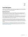
The E1200 System
The Dell Force10 E1200 system is a carrier-class, high-capacity aggregation router. The 16-slot modular
system provides two slots dedicated for Route Processor Modules (RPMs) and 14 slots for line cards with
Layer 2 switching and Layer 3 and routing capabilities.
Operating Overview
The E1200 system requires a Route Processor Module (RPM), at least one line card, and at least eight
Switch Fabric Modules (SFMs) for packet processing. The RPM is the core for routing and control
operations; all traffic destined to the E1200i terminates on the RPM. Routing table entries are built on the
RPM and directed to the forwarding information tables on the line cards.
Software processes, such as Telnet, SNMP, CLI, Layer 2, and Layer 3 functions, are divided among three
CPUs for redundancy and speed. Independent software images run on each CPU. Each CPU has its own
memory, which isolates processes from each other, increasing reliability. Operating the E1200 system
with redundant RPMs enables automatic fail-over redundancy.
Line cards perform all data forwarding operations. Each line card has Dell Force10 proprietary ASICs —
the flexible packet classification (FPC) ASIC and the Buffer and Traffic Manager (BTM) ASIC. The FPC
accepts packets, feeds packets to input/output ports, handles packet classification (access lists, and Layer
2 and Layer 3 lookups), and packet-marking (Diffserv or 802.1p). The BTM is responsible for all queuing
operations.
The internal flash memory device shipped with the RPM contains the boot ROM and runtime images.
Each RPM accommodates an external flash memory card that can be used to copy and store system boot,
software images, and configuration files. For information about using a flash card, refer to Appendix A,
Using a Flash Memory Card, on page 65.
The E1200 System
|
9
www.dell.com | support.dell.com
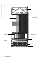
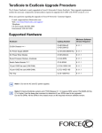
Figure 2-1.
E1200i AC Chassis Front View
Cable Management System
Line Card Slots
Line Card Slots
RPM 1
Switch Fabric
Module (SFM)
Blank (BLNK)
Air Filter
Air Vents
AC Power Supply
AC Power Plug
10
|
The E1200 System
Figure 2-2.
E1200 AC Chassis Rear View
locking screw
Installed Fan Tray
Empty Fan Tray with
Self-closing Door
Ground Connection
Ground Connection
The E1200 System
|
11
www.dell.com | support.dell.com
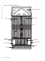
Figure 2-3.
E1200i DC Chassis Front View
Cable Management System
Line Card Slots
Line Card Slots
RPM 1
Switch Fabric
Module (SFM)
Blank (BLNK)
DC Power Supply
DC Power Supply
Air Filter
Air Vents
12
|
The E1200 System
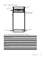
Figure 2-4.
E1200 DC Chassis Rear View
Locking screw
Installed Fan Tray
Empty Fan Tray with
Self-closing Door
Ground Connection
Ground Connection
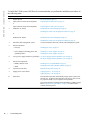
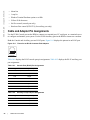
Table 2-1.
E1200 Hardware Component Operating Requirements Summary
Component
Minimum
Maximum
Field-Replaceable
Backplane (factory installed)
1
1
N
Air filter (factory installed)
1
1
Y
Fan trays
2
2
Y
RPMs
1
2
Y
Line cards
1
14
Y
SFMs
8
9
Y
AC Power Supply
2
6
Y
DC Power Supply
1
2
Y
Cable management system
0
1
Y
Cable management system cover
0
1
Y
The E1200 System
|
13
www.dell.com | support.dell.com
To install the E1200 system, Dell Force10 recommends that you perform the installation procedures in
the following order:
Step
Task
Section
1
Prepare the site
Site Preparation on page 15
2
Unpack the AC chassis and components
or
Unpack the DC chassis and components
Unpacking the E1200 System on page 19
Mount the AC chassis
Standard Front Chassis Mounting on page 20
Installing the Chassis into an Equipment Cabinet on page 21
3
or
Mount the DC chassis
Standard Front Chassis Mounting on page 24
Installing the Chassis into an Equipment Cabinet on page 25
4
Install the cable management system
See the instructions that come with the cable management system.
5
Install components:
• Fan trays
Installing Fan Trays on page 27
• Power Supplies (including power and
grounding cables)
Installing AC Power Supplies on page 29
Installing DC Power Supplies on page 33
6
Verify power supply and fan tray operability AC Power Supply and Fan Operability Test on page 31
DC Power Supply and Fan Operability Test on page 38
7
Install card components:
• RPM(s) and line cards
• SFMs
|
Installing Line Cards and RPMs on page 42
Installing Switch Fabric Modules (SFMs) on page 46
8
Connect network cable
RPM Ports and Cables on page 49
9
Supply power to the chassis
Supplying Power - AC on page 54
Supplying Power - DC on page 54
Initial boot
The initial boot operation automatically brings up the system to the
runtime CLI. To interrupt the automatic boot process, issue a break
key sequence (Ctrl^) if you experience boot problems.
The console monitor will display the default BOOT_USER # prompt.
Refer to Appendix B, System Boot, on page 69 for instructions to
continue the boot process.
10
14
Unpacking the E1200 System on page 23
The E1200 System
3
Site Preparation
This chapter describes factors to consider before installing your E1200 system. The following topics are
discussed:
• Site Selection Criteria on page 15
• Rack Mounting on page 16
• Cabinet Placement on page 16
• Power on page 16
• Fans and Airflow on page 17
• Storing Components on page 17
For complete E1200 System Specifications, refer to Appendix D, System Specifications, on page 79.
Site Selection Criteria
Before you begin the installation process, make sure that the area where you intend to install your E1200
meets the following safety requirements.
Select a site:
• In a restricted access area.
• In a dry, clean, well-ventilated and temperature-controlled room, away from nearby heat sources such as
hot air vents or direct sunlight.
• Away from sources of severe electromagnetic noise.
• Near an adequate power source. Connect the E1200 to the appropriate branch circuit protection as
defined by local electrical codes.
• Means of power disconnect must be located near the equipment
• Position in a rack with adequate space in the front and rear, and sides of the unit for proper ventilation,
access to cables, and maintenance access. Allow at least 18 inches in the front and 20 inches in the rear
of the rack for ventilation. If placing the chassis in a cabinet, ensure that there is enough clearance
between the closed cabinet door and the cables in the cable management system on the chassis.
CAUTION: Lift the E1200 chassis either from the bottom or by the handles provided with the front shipping
cover. Lifting by the chassis shelves or fan tray openings will cause chassis damage. Do not remove the
protective front shipping cover until the chassis is secured in the equipment rack.
Site Preparation
|
15
www.dell.com | support.dell.com
Rack Mounting
When you prepare your equipment rack, make sure the rack is bolted to the floor and/or braced to a wall
or ceiling.
When you install the chassis:
• Make sure that the rack is grounded to the grounding electrode. Each DC PEM must be grounded to the
rack or building ground bus. The equipment rack must be grounded to the same grounding electrode
used by the power service in your area. The ground path must be permanent.
• Install the E1200 chassis in the rack before you install internal components or make network and power
connections.
• In an empty rack, place the chassis in the lower half of the rack to ensure rack stability.
Cabinet Placement
The cabinet must meet the following criteria:
• Minimum cabinet size is 30 inches deep and 24 inches wide.
• Minimum air flow is 750 cubic feet per minute (CFM).
• Minimum of 3 inches between the closed doors and the front of the cable management panel, and a
minimum of 3 inches between the chassis rear and the rear of the cabinet with the cabinet door closed.
With the rear doors of the cabinet open, you will need a clearance of at least 20 inches from the rear to
access the chassis fan trays.
• Minimum of 20 inches clearance at the chassis front to access the air filter, power supplies, and cards.
Power
At a minimum, the E1200 requires either 2 AC Power Supplies or 1 DC PEM to operate.
CAUTION: You cannot power the system with both types of power supply module installed. The system must
contain only one type of power module, either AC or DC.
CAUTION: The E1200i AC Chassis is shipped with blank inserts covering the DC PEM openings. DO NOT
REMOVE THEM. The blank inserts must remain installed for proper system cooling and for EMI containments
during system operation.
WARNING:
•
•
•
Make your chassis ground connections first (see Figure 2-2). If the chassis is not correctly grounded,
excessive electromagnet emission may result.
Disconnect all power to the equipment rack or cabinet before chassis installation.
Never operate the E1200 system with empty RPM, SFM, or line card slots. Always replace empty slots
with blank panels.
Each E1200 system requires at least two AC Power Supplies or at least one DC Power Supply to operate.
Three AC units are required for power supply redundancy, four AC units are required for full facility
redundancy, and six AC units provide 3+3 redundancy
16
|
Site Preparation
Two DC units are required for power supply and full facility redundancy.
WARNING: Leakage Current (High Touch Current): The AC power cords are secured to the power inlet using
the provided bracket. The AC power cord plugs must be secured to the building outlets by the chassis installer
or a qualified electrician.
Refer to Appendix D, System Specifications, on page 79 for specifications on thermal output and other
power related numbers.
Fans and Airflow
Your E1200 chassis contains two field-replaceable fan trays. Air flows through the system from a
filtered-intake vent located in the lower part of the chassis. Air circulates from the bottom front (and
sides) to the back and exhausts through a top rear vent. The variable fan speed is reduced at normal
operating temperatures and increases to full speed as operating temperatures increase, up to 104° F
(40° C).
For fan tray access, maintenance and proper ventilation, position the chassis and equipment rack or
cabinet so that:
• At least three inches clearance is around the front and side intake and exhaust vents for free air flow
• Provide 20 inches in the rear to access the fan tray.
• Operate the E1200 system with two fan trays.
For instructions on replacing a fan tray, refer to Removing and Replacing Fan Trays on page 57.
Storing Components
CAUTION: Do not transport a chassis with components (line cards, power supplies, RPMs, Fan Trays, Power
Supply, or SFMs) installed in the chassis. Place the modules in their original ESD-preventative packaging and
attach the Front Shipping Cover on the front of the chassis prior to placing the chassis in its original shipping
crate. Shipping the chassis with components installed may damage the components and the chassis
backplane.
If you do not install your E1200 system and components right away, Dell Force10 recommends that you
properly store components and all extra field-replaceable components (spares) until you are ready to
install them. Keep all components in the original packaging during storage.
Follow these indoor storage guidelines:
• Storage temperature should remain constant ranging from -40° to 158°F (-40° to 70°C).
• Non-condensing relative humidity should be maintained within 5 to 95 percent.
• Store on a dry floor, away from direct sunlight, heat, and air conditioning ducts.
• Store in a dust-free environment.
Site Preparation
|
17
18
|
Site Preparation
www.dell.com | support.dell.com
4
Installing the AC Chassis
This chapter provides instructions to rack mount your E1200 system into a standard 19-inch or 23-inch
equipment rack. It contains the following sections:
• Unpacking the E1200 System
• Installing the Equipment Rack Shelf Bar
• Standard Front Chassis Mounting
• Installing the Chassis into an Equipment Cabinet
Unpacking the E1200 System
The E1200 AC system and components are shipped on a wooden pallet with Front Shipping cover.
Remove the chassis from the shipping packaging and move the chassis with a hand cart, pallet jack, or
fork lift to its rack. Do not unpack the power supplies, fan trays, air filter, or cards until the chassis is
installed.
WARNING: The E1200 AC shipping containers each weigh up to 400 pounds. The unpacked chassis and
pallet weigh approximately 200 pounds. Do not attempt to lift or move the chassis without the use of a hand
cart, pallet jack, or forklift.
CAUTION: Lift the E1200 chassis only with the handles provided or from the bottom. Lifting by the chassis
shelves will cause chassis damage. Do not remove the shipping cover during the installation process. The
cover prevents damage to the internal framework and EMI seals.
WARNING: Electrostatic discharge (ESD) damage can occur when components are mishandled. Always
wear an ESD-preventative wrist or foot-heal ground strap when handling RPMs, SFMs, or line cards. After you
remove the original packaging, place RPMs, SFMs, and line cards directly into the chassis, or on an antistatic
surface.
WARNING: Complete the chassis installation into the rack before you install any other component (fan trays,
power supplies, line cards, RPMs, SFMs, cables).
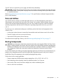
Installing the Equipment Rack Shelf Bar
The rack shelf bar (Figure 4-1) enables you to easily position the chassis into the rack and provides the
unit additional stability. The E1200 system must be mounted in a rack that is permanently secured to the
floor.
Installing the AC Chassis
|
19
Rack Shelf Bar
UP
UP
FN
www.dell.com | support.dell.com
Figure 4-1.
To install a equipment rack shelf bar:
Step
Task
1
Determine the chassis mounting location in the equipment rack.
2
Orient the bar with the arrows pointing upward. The smooth side of the bar should face outward.
3
Attach the bar to the equipment rack brackets using the mounting screws provided by the manufacturer.
Standard Front Chassis Mounting
NOTE: Dell Force10 recommends that you install and operate the E1200 system in a standard 19-inch or 23inch equipment rack.
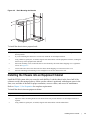
Install the E1200 system after you secure the equipment rack shelf bar. Load the chassis in the lower half
of an empty rack to avoid a top-heavy rack (Figure 4-2).
WARNING: Do not remove the Front shipping Cover during the initial installation process. The cover provides
front handles to assist in lifting and prevents damage to the internal framework and EMI seals.
20
|
Installing the AC Chassis
Figure 4-2.
Rack Mounting the Chassis
FN00046B
To install the chassis into a prepared rack:
Step
Task
1
If you are center or rear-mounting the chassis in a 19-inch rack, adjust the chassis rack mounting brackets to the
desired position.
2
If you are mounting the chassis in a 23-inch rack, install the 23-inch adapter brackets.
3
Using a hand cart, pallet jack, or forklift, align the rack-mount holes with the equipment rack holes, situating the
chassis on top of the equipment rack shelf bar.
4
Insert rack mounting screws in the holes that are not obscured by the metal chassis shipping cover. Tighten the
screws. See Figure 4-2.
5
Loosen and remove the screws that secure the chassis Front Shipping Cover and remove the cover.
6
Insert the remaining rack mounting screws and tighten to secure the chassis in the rack.
Installing the Chassis into an Equipment Cabinet
Install the E1200 system after you secure the rack shelf bar. Load the chassis in the lower half of the
cabinet to avoid it becoming top-heavy. Make sure the cabinet is positioned with adequate space in the
front, rear, and sides of the unit for proper ventilation, access to cables, and access for maintenance.
Refer to Chapter 3, Site Preparation for complete requirements.
To install the chassis into an equipment cabinet:
Step
Task
1
Install the equipment rack shelf bar.
2
Adjust the chassis mounting brackets to the desired front-rear position and add a 23-inch adapter brackets as
required.
3
Using a hand cart, pallet jack, or forklift, align the rack-mount holes with the cabinet holes.
Installing the AC Chassis
|
21
www.dell.com | support.dell.com
Step
22
|
Task
4
Insert rack mounting screws in the holes that are not obscured by the metal chassis shipping cover. Tighten the
screws.
5
Loosen and remove the screws attaching the chassis shipping cover. Remove the shipping cover.
6
Insert the remaining mounting screws and tighten to secure the chassis in the cabinet.
Installing the AC Chassis
5
Installing the DC Chassis
This chapter provides instructions to rack mount your E1200 system into a standard 19-inch or 23-inch
equipment rack. It contains the following sections:
• Unpacking the E1200 System
• Installing the Equipment Rack Shelf Bar
• Standard Front Chassis Mounting
• Installing the Chassis into an Equipment Cabinet
Unpacking the E1200 System
The E1200 DC system and components are shipped on a wooden pallet with Front Shipping cover.
Remove the chassis from the shipping packaging and move the chassis with a hand cart, pallet jack, or
fork lift to its rack. Do not unpack the power supplies, fan trays, air filter, or cards until the chassis is
installed.
WARNING: The E1200 DC shipping containers each weigh up to 400 pounds. The unpacked chassis and
pallet weigh approximately 200 pounds. Do not attempt to lift or move the chassis without the use of a hand
cart, pallet jack, or forklift.
CAUTION: Lift the E1200 chassis only with the handles provided or from the bottom. Lifting by the chassis
shelves will cause chassis damage. Do not remove the shipping cover during the installation process. The
cover prevents damage to the internal framework and EMI seals.
WARNING: Electrostatic discharge (ESD) damage can occur when components are mishandled. Always
wear an ESD-preventative wrist or foot-heal ground strap when handling RPMs, SFMs, or line cards. After you
remove the original packaging, place RPMs, SFMs, and line cards directly into the chassis or on an antistatic
surface.
WARNING: Complete the chassis installation into the rack before you install any other component (fan trays,
power supplies, line cards, RPMs, SFMs, cables).
Installing the Equipment Rack Shelf Bar
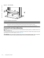
The rack shelf bar (Figure 5-1) enables you to easily position the chassis into the rack and provides the
unit additional stability. The E1200 system must be mounted in a rack that is permanently secured to the
floor.
Installing the DC Chassis
|
23
Rack Shelf Bar
UP
UP
FN
www.dell.com | support.dell.com
Figure 5-1.
To install a equipment rack shelf bar:
Step
Task
1
Determine the chassis mounting location in the equipment rack.
2
Orient the bar with the arrows pointing upward. The smooth side of the bar should face outward.
3
Attach the bar to the equipment rack brackets using the mounting screws provided by the manufacturer.
Standard Front Chassis Mounting
NOTE: Dell Force10 recommends that you install and operate the E1200 system in a standard 19-inch or 23inch equipment rack.
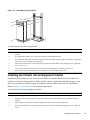
Install the E1200 system after you secure the equipment rack shelf bar. Load the chassis in the lower half
of an empty rack to avoid a top-heavy rack (Figure 5-2).
WARNING: Do not remove the Front shipping Cover during the initial installation process. The cover provides
front handles to assist in lifting and prevents damage to the internal framework and EMI seals.
24
|
Installing the DC Chassis
Figure 5-2.
Rack-Mounting the Chassis’
FN00046B
To install the chassis into a prepared rack:
Step
Task
1
If you center- or rear-mount the chassis in a 19-inch rack, adjust the chassis rack-mounting brackets to the desired
position.
2
If you mount the chassis in a 23-inch rack, install the 23-inch adapter brackets.
3
Use a hand cart, pallet jack, or forklift to align the rack-mount holes with the equipment rack holes, situating the
chassis on top of the equipment rack shelf bar.
4
Insert rack-mounting screws in the holes that are not obscured by the metal chassis shipping cover. Tighten the
screws. See Figure 5-2.
5
Loosen and remove the screws that secure the chassis Front Shipping Cover and remove the cover.
6
Insert the remaining rack-mounting screws and tighten to secure the chassis in the rack.
Installing the Chassis into an Equipment Cabinet
Install the E1200 system after you secure the rack shelf bar. Load the chassis in the lower half of the
cabinet to avoid it becoming top-heavy. Make sure the cabinet is positioned with adequate space in the
front, rear, and sides of the unit for proper ventilation, access to cables, and access for maintenance.
Refer to Chapter 3, Site Preparation for complete requirements.
To install the chassis into an equipment cabinet:
Step
Task
1
Install the equipment rack shelf bar.
2
Adjust the chassis mounting brackets to the desired front-rear position and add a 23-inch adapter brackets as
required.
3
Using a hand cart, pallet jack, or forklift, align the rack-mount holes with the cabinet holes.
4
Insert rack-mounting screws in the holes that are not obscured by the metal chassis shipping cover. Tighten the
screws.
Installing the DC Chassis
|
25
www.dell.com | support.dell.com
Step
26
|
Task
5
Loosen and remove the screws attaching the chassis shipping cover. Remove the shipping cover.
6
Insert the remaining mounting screws and tighten to secure the chassis in the cabinet.
Installing the DC Chassis
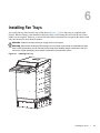
6
Installing Fan Trays
Access the fan tray slots from the rear of the chassis (Figure 6-1). Two fan trays are required in the
chassis. When a fan tray is not installed in the lower slot, a self-closing door will seal the slot. Panel
blanks are not required. However, to ensure fail-safe chassis operation, do not operate the chassis with
only one fan tray for more than 30 minutes.
WARNING: Install the fan trays before you supply power to the system.
WARNING: Electrostatic discharge (ESD) damage can occur when components are mishandled. Always
wear an ESD-preventative wrist or foot-heal ground strap when handling chassis components. After you
remove the original packaging, place chassis components on an antistatic surface.
Figure 6-1.
Installing Fan Tray
Installing Fan Trays
|
27
www.dell.com | support.dell.com
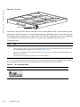
Figure 6-2.
Fan Tray
screw latch
Install the fan trays after the chassis is installed securely in the equipment rack. Access the fan tray slots
from the rear side of the chassis. To ensure proper temperature and airflow control, all six fan trays must
be installed before you supply power to the system. You will need a #2 Phillips screwdriver to tighten the
screws that secure the fan trays to the chassis. A fan tray can be installed in any fan tray slot.
To install fan trays:
Step
Task
1
Unpack the fan tray.
2
Prior to inserting a fan tray, fully turn its screw latch counter-clockwise (with flathead screwdriver) until the fan
tray latching mechanism fully retracts into the fan tray (see Figure 6-2).
3
Grip the fan tray handle. Slide the connector end of each fan tray into the slot until it stops and the handle end is
flush with the chassis rear.
4
Secure the fan trays into place by turning the screw latch clockwise.
Table 6-1 is an illustration of the fan tray safety labels: Prevent exposure and contact with hazardous voltages.
Do not attempt to operate this system without the safety cover provided with each PEM.
Table 6-1.
Fan Tray Safety Labels
Label
Location
Fan tray faceplate
28
|
Installing Fan Trays
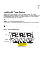
7
Installing AC Power Supplies
The E1200 system requires a minimum of two AC power supplies to operate, three for power
redundancy, four for facility redundancy (2+2), and 6 for 3+3 redundancy. To comply with safety agency
and EMI regulations, you must install the AC-cord retainer over all power cords. The E1200 chassis
contains six AC power supply slots, as shown in Figure 7-1.
NOTE: If you are installing only two power supplies, they must be installed in the same row. FTOS will
generate an error message if the two power supplies are not in the same row.
NOTE: If you are installing power supplies for redundancy:
• For 2+2 redundancy, two power supplies must reside in each row. That is, two in the top row and two in the bottom row.
• For redundant operation with only three power supplies, install all three power supplies in the same row.
NOTE: The On/Standby switch disconnects power to the rest of the chassis from all 6 AC power supplies.
• When the AC cord is attached, power supply fans will spin and the LEDs will indicate status while the On/Standby switch
is in Standby.
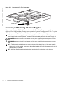
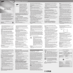
Figure 7-1.
E1200i AC Power Supply Shelf
Power
Supplies
AC-0
AC-1
AC-2
AC-3
AC-4
AC-5
On/Standby
Switch
AC-Cord Retainer
Safety Cover
AC-0
AC-3
AC-1
AC-4
WARNING HIGH LEAKAGE CURRENT. EARTH CONNECTION
ESSENTIAL BEFORE CONNECTING SUPPLY.
COURANT DE FUITE ELEVE. RACCORDEMENT
A LATERRE INDISPENSABLE AVANT LE
RACCORDEMENT AU RESEAU.
AC-2
AC-5
AC Power Plugs
Locking Screw
/
/
/
This retainer must be in place during normal operation.
Do not remove except for servicing
Installing AC Power Supplies
|
29
www.dell.com | support.dell.com
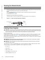
Securing the Chassis Ground
Step
Task
1
Locate the chassis ground connector nuts on the chassis rear (see Figure 2-2 on page 11).
2
Install the grounding cables to the ground nuts. The grounding cable must comply with your local electrical codes in
size and color (typically the color is green or green with yellow stripe).
NOTE: Grounding cables must be terminated only with a UL-listed 2-hole lug with 1/4-inch holes on
3/4-inch spacing (see Figure 7-2).
Use ANSI UNC 1/4-20 x 1/2 bolt.
Tighten the bolt (torque should not exceed 25inch/lbs).
Connect the opposite end of the grounding cable to the nearest appropriate facility grounding post.
Figure 7-2.
Cable Connector Required for E1200i AC
0.267
diameter
2 Holes
High-strand-count
conductor
0.750"
FN00011A
All measurements in inches.
Installing Power Supplies
CAUTION: An E1200i AC power supply still has power after extraction, and has completely powered off when
the fans have stopped rotating. When replacing a power supply, to avoid arcing and discoloration of the supply
and the chassis pins, please wait for the fans to stop rotating before reinserting the supply
Power Cord Requirements
If using a power cord other then a Dell Force10 supplied power cord, the cord must terminate at a right
angle to the power module, see Figure 7-1. The power source end of the power cord must have an
appropriately sized plug that complies with your local electrical codes. Conductor size must also conform
to your local electrical codes.
CAUTION: The power cord is the main power disconnect device; ensure that the socket-outlet is located/
installed near the equipment and is easily accessible.
CAUTION: There are multiple power cords that require disconnecting. Disconnect all power cords before
servicing the power module.
The following are Force 10 supplied plug types. All power plug must comply with local codes. Check
with your Force 10 representative to purchase cords or plugs for your system.
• EU: CEE 7/7
• UK: CEE7/7
• SWZ: CEE7/7, 309
• JAP: NEMA 6-20, L6-20, L6-30
• JAP 220: NEMA 6-20, L6-20
30
|
Installing AC Power Supplies
• US: C14, C20
• US 220: NEMA 6-20, L6-20, L6-30 (30A)
CAUTION: The power cord is the main power disconnect device; ensure that the socket-outlet is located/
installed near the equipment and is easily accessible.
Step
Task
1
Make sure that the On/Standby switch, located on the left side of plug AC-0, is in the Standby (up) position
(Figure 7-1).
2
Loosen the cord retainers locking screws (if needed) and tilt the AC-cord retainer up approximately 15o and gently
slide the cover away from the chassis.
3
Slide the power supplies into their slots until the module front is flush with the shelf front.
Figure 7-3.
Insert power supply
4
Connect the Power Supply cord to the designated socket (Figure 7-1).
5
Re-install the AC-cord Retainer by tilting approximately 15o and gently sliding in the long edge just above the AC
cords.
6
Secure the retainer by tighten the locking screws on either side of the retainer.
WARNING: Leakage Current (High Touch Current) in AC-powered systems: AC power cords are secured to
the power inlet using the provided brackets. The power cord plugs must be secured to the building outlets by
the qualified chassis installer or a qualified electrician.
AC Power Supply and Fan Operability Test
Once your power supplies and fan trays are installed, verify their operability by supplying power to the
chassis and verifying the status LEDs.
Before you begin this power test, inspect your equipment rack and chassis. Verify that:
• Each Power Supply is properly installed and plugged into the assigned slot.
• The AC-cord Retainer is secured over the plugs.
Installing AC Power Supplies
|
31
www.dell.com | support.dell.com
WARNING: Prevent exposure and contact with hazardous voltages. Do not attempt to operate this system
without the AC-cord Retainer.
• Your power cables connect to an appropriate AC power supply in a manner that complies with your
local electrical codes. For AC systems, a Main Disconnect must be provided for each AC cord.
• Two fan trays are installed.
To test the power supplies and fan trays:
Step
Task
With the fan trays and power supplies installed, power on the system.
1
• Flip the On/Standby switch located next to plug AC-0 to the ON position (down).
Power Supply Status LEDs should be green. If an LED is not lit or is blinking amber:
2
• check that the units are properly installed and are plugged into the correct slot.
• Verify the power source
• If the LED remains unlit or blinking amber at power up, replace the power supply.
Both fan tray LEDs should be green (online). A blinking green fan tray LED indicates booting. Verify that air is
flowing through the chassis. If a fan tray is not operating properly or air is not flowing through the chassis:
3
• power off the chassis at the remote power source.
• Ensure that all fan trays are properly installed.
• Verify the remote power source.
• If a fan tray LED remains unlit, replace the fan tray.
4
After you have verified the power and fan operability, power off the chassis to continue the installation process.
5
De-energize the Main Disconnect and flip the On-Off switch to the OFF position.
6
Verify that the LEDs are not lit.
Power Supply and Fan Tray LEDs
Table 7-1.
Status
LED is ...
No AC power
Unlit: No connection
Operational (On/Standby switch may be set to Standby)
Lit: GREEN
Power Supply Failure
Lit: AMBER
Table 7-2.
32
|
Power Supply LEDs
Fan Tray LEDs
Status
LED is ...
Booting
Blinking: GREEN
Fault Detected
Lit: YELLOW
Communication Failure
Blinking: YELLOW
Operational
Lit: GREEN
Loss of Power
Unlit
Installing AC Power Supplies
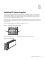
8
Installing DC Power Supplies
The E1200 system requires a minimum of one DC Power Entry Module (PEM) to operate, but two are
recommended for redundancy. To comply with safety agency and EMI regulations, you must install
covers on all power supply slots not containing a PEM. Connect the PEMs to the appropriate branch
circuit protection as defined by local electrical codes.
For full redundancy, each PEM must be attached to an independent power source with a dedicated circuit
breaker. For example, the PEM in slot 0 connects to circuit breaker A and the PEM in slot 1 connects to
circuit breaker B.
The E1200 chassis contains two DC PEM slots, as shown in Figure 8-1.
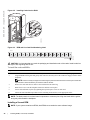
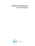
Figure 8-1.
PEM 0 and PEM 1 Chassis Locations
21
21
22
21
22
21
22
21
22
21
22
21
22
21
22
23
23
23
23
23
21
22
PRIMARY
23
21
22
21
22
21
22
21
22
21
22
22
PRIMARY
23
23
23
23
23
23
23
23
RP4L-RPMC
RP4L-RPMC
RP4L-RPMC
RP4L-RPMC
RP4L-RPMC
RP4L-RPMC
RP4L-RPMC
RP4L-RPMC
RP4L-RPMC
RP4L-RPMC
RP4L-RPMC
RP4L-RPMC
RP4L-RPMC
RP4L-RPMC
RP4L-RPMC
RP4L-RPMC
Force10 Networks
Force10 Networks
Force10 Networks
Force10 Networks
Force10 Networks
Force10 Networks
Force10 Networks
Force10 Networks
Force10 Networks
Force10 Networks
Force10 Networks
Force10 Networks
Force10 Networks
Force10 Networks
Force10 Networks
Force10 Networks
online
online
online
online
online
online
online
online
online
online
online
online
online
online
online
online
fail
fail
fail
fail
fail
fail
fail
fail
reset
fail
reset
fail
fail
fail
fail
fail
fail
fail
online
online
fail
PEM 0
fail
SF4L-SFMC
Force10 Networks
online
fail
SF4L-SFMC
SF4L-SFMC
SF4L-SFMC
SF4L-SFMC
SF4L-SFMC
SF4L-SFMC
SF4L-SFMC
SF4L-SFMC
SF4L-SFMC
Force10 Networks
Force10 Networks
Force10 Networks
Force10 Networks
Force10 Networks
Force10 Networks
Force10 Networks
Force10 Networks
Force10 Networks
online
online
online
online
online
online
online
online
online
fail
fail
fail
fail
fail
fail
fail
fail
fail
PEM 1
FN00100lp
The DC PEM shown in Figure 8-2 is used in both the E1200 and E1200i DC chassis.
Figure 8-2.
E1200i DC PEM
FN00101lp
Installing DC Power Supplies
|
33
www.dell.com | support.dell.com
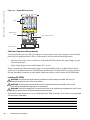
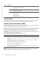
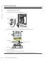
Figure 8-3.
E1200 PEM Front Panel
Studs
PEM interlock
lever
Over-current protector
Latch Release
Status
-48/-60Vdc
150A, 7200VA
CC-E1200-PWR-DC
FN00102lp
Locking screws
Cable and Connector Requirements
You must provide your own cables to connect to a remote power source (for example, a circuit breaker
panel) in your equipment rack or office. Cables must be sized to meet the following criteria:
• rated for at least 150A service to allow for a fully loaded E1200 system at low input voltage per your
local electrical codes
• limits voltage drop across the cable length to 0.5V or less
Before you make the cable connections, apply a coat of antioxidant paste to un-plated metal contact
surfaces. File un-plated connectors, braided straps, and bus bars to a shiny finish. It is not necessary to
file and coat tinned connectors or other plated connection surfaces, such as on the E1200 PEM studs.
Installing DC PEMs
WARNING: An external disconnect shall be provided and shall be easily accessible. Dell Force10
recommends that you use a 150A circuit breaker.
WARNING: Un interrupteur externe doit être fournis et doit êtrefacilement accessible. Dell Force10
recommande l'utilisationd'un disjoncteur de 150Ampères.
WARNING: Eine leicht zugängliche Trennvorrichtung muss in der Verdrahtung eingebaut sein. Dell Force10
empfiehlt, dass Sieeinen 150A Sicherungsautomaten benutzen.
Each E1200 system requires at least one load-sharing DC PEM to operate. Two units are recommended
for full facility redundancy.
34
|
Parameter
Specifications
Maximum DC PEM Input Current
150A
Maximum Power Dissipation
6850W (21,598 BTU/hour)
Input Voltage
-48 to -60 Vdc
Installing DC Power Supplies
Use the following steps to install a DC PEM:
Step
Task
1
Make sure that the remote power source (the circuit breaker panel) is in the OFF position.
2
Make sure that the over-current protector (located on the PEM front panel) is in the OFF position.
3
Loosen the retaining screw and remove the PEM safety cover.
R etaining
s crew
S afety
cover
FN00103lp
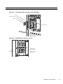
4
Slide the PEM into the 0 or 1 slot (Figure ):
Lift up and hold the PEM interlock lever and carefully push the unit inward to fully seat it to the backplane. When the
PEM is fully inserted, the interlock lever will drop to hold the PEM in position.
Tighten the two locking screws with a #2 Phillips screw driver to secure the PEM. Do not exceed
5 inch/lbs torque.
Over current protector
PEM interlock lever
Locking screws
fn00104lp
Installing DC Power Supplies
|
35
www.dell.com | support.dell.com
Step
5
Task (continued)
Secure the chassis ground connection first:
Remove one outer nut and one washer from each of the six studs. One nut should remain, tight on the stud. If the
inner nut is loose, re-tighten it to 25 inch/lbs. maximum.
Locate the chassis ground connector studs on the PEM front panel (see Figure 8-3). The two rightmost studs are the
ground connection.
Install the grounding cable onto the ground studs. The grounding cable must comply with your local electrical codes
in size and color (typically the color is green or green with yellow stripe).
NOTE: Grounding cables must be terminated only with a UL-listed 2-hole lug with 1/4-inch holes on 3/4-inch
spacing (see Figure 8-4).
Replace the two washers and nuts on the studs.
With a 7/16-inch box or socket wrench, tighten the nuts (torque should not exceed 25inch/lbs).
Connect the opposite end of the grounding cable to the nearest appropriate facility grounding post.
Figure 8-4.
Cable Connector Required for E1200 PEM
All meas urements s hown in inches .
fn00105lp
High-s trand-count
conductor
0.267
diameter
2 Holes
0.750"
6
Connect the -48 VDC and Return cables from each PEM to the remote power sources (circuit breakers A and B).
Check that the remote power sources (for example, circuit breakers) are in the OFF position.
Locate the appropriate studs on the PEM front panel (Figure 8-3).
The two leftmost studs on the PEM are the -48 VDC (-) connection. The cable attached to these studs is typically
black.
• The two middle studs are the return (+) connection. The cable attached to these studs is typically red.
Install the -48 VDC and Return cables on the studs. The cables should be of the size and color to comply with local
electrical codes.
Note: Power cables must be terminated only with a UL-listed 2-hole lug with 1/4-inch studs with 3/4-inch spacing
(Figure 8-6).
Replace the washers and nuts on the studs.
With a 7/16-inch box or socket wrench, tighten the nuts.
36
|
Installing DC Power Supplies
Step
7
Task (continued)
Route the terminated cables down and toward the rack rail, as shown below.
Figure 8-5.
Connecting the Ground Cable to the E1200 PEM
Lug
Split-lock washer
Lug nuts
Ground studs
fn00106lp
Figure 8-6.
DC PEM with Connections in Place
Ground cable
typically green
-48 (-) cable
typically black
Return cable (+)
typically red
fn00106lp
Installing DC Power Supplies
|
37
www.dell.com | support.dell.com
Step
8
Task (continued)
Replace the safety cover and tighten the captive screw with a #2 Phillips screwdriver (Figure 8-7).
Figure 8-7.
Reinstalling the PEM Safety Cover
fn00108lp
9
10
Check that the over-current protector (located on the PEM front panel) is in the OFF position.
Energize the remote power source. The Voltage LED should be green. If it is amber, the -48 VDC and Return cables
are connected incorrectly or are reversed.
Go to DC Power Supply and Fan Operability Test, next, to complete the installation.
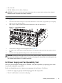
DC Power Supply and Fan Operability Test
After you have completed the fan tray and PEM installation, verify their operability by supplying power
to the chassis and verifying the status LEDs.
NOTE: If there is a DC PEM failure, the entire PEM must be replaced. There are no field-serviceable parts
inside the DC PEM unit.
Before you begin this power test, inspect your equipment rack and chassis. Verify that:
• Each PEM is properly installed and grounded.
• The safety covers are installed on each PEM.
WARNING: Prevent exposure and contact with hazardous voltages. Do not attempt to operate this system
without the safety cover provided with each DC PEM.
• Your power cables connect to an appropriate DC supply in a manner that complies with your local
electrical codes. For DC systems, a Main Disconnect must be provided.
• On the DC PEM(s), use a voltage meter to verify power on the cables. Also verify that the Voltage LED
is green.
38
|
Installing DC Power Supplies
• A power supply blank is installed in any empty slot.
• Six fan trays are installed.
To test the power supplies and fan trays:
Step
1
Task
With the fan trays and DC PEMs installed, power on the system.
• Flip the over-current protector (located on the PEM front panel) to the ON position.
2
PEM Status LEDs should be green.
If an LED is not lit or is amber, check that the unit is properly installed. Verify the power source. If the LED
remains unlit, power off all modules and replace the unit.
3
All six fan tray LEDs should be green (online). Verify that air is flowing through the chassis.
If a fan tray is not operating properly or air is not flowing through the chassis, power off the chassis at the remote
power source. Ensure that all fan trays are properly installed. Verify the remote power source. If a fan tray LED
remains unlit, replace the fan tray.
4
After you have verified the power and fan operability, power off the chassis to continue the installation process.
5
De-energize the Main Disconnect and flip the over-current protector to the OFF position.
6
Verify that the LEDs are not lit.
Installing DC Power Supplies
|
39
www.dell.com | support.dell.com
40
|
Installing DC Power Supplies
9
Installing RPMs, Line Cards, and SFMs
This chapter provides instructions for installing cards into the E1200 AC or DC chassis. It contains the
following sections:
• Unpacking an RPM or Line Card
• Installing Line Cards and RPMs
• Preparing and Installing RPMs and Line Cards
• RPM Label and LEDs
• Installing Switch Fabric Modules (SFMs)
• Line Card Cable Management Systems
Unpacking an RPM or Line Card
WARNING:
•
•
•
Electrostatic discharge (ESD) damage can occur when components are mishandled. Always wear an
ESD-preventive wrist or foot-heel ground strap when handling RPMs, SFMs, or line cards. Connect your
ESD strap to the grounding plug located on the front of the chassis. See Figure 2-2 for ESD strap
connector location. After you remove the original packaging, place RPMs, SFMs, and line cards on an
antistatic surface.
Electrostatic discharge (ESD) damage can occur when components are mishandled. Always wear an
ESD-preventive wrist or foot-heel ground strap when handling RPMs, SFMs, or line cards. After you
remove the original packaging, place RPMs, SFMs, and line cards on an antistatic surface.
Do not supply power to your E1200 system until the power supplies and fan tray(s) are installed and
verified, and RPMs, SFMs, line cards, and any blank panels are installed.
Dell Force10 recommends that you keep all components in the original packaging until you are ready to
install them.
Important Points to Remember
• Do NOT remove the cards from their protective bags until you are ready to install them in a chassis.
• When you are ready to install the cards, unwrap and install one card at a time, starting with the rightmost slot (Slot 13 for line cards, Slot R1 for RPMs, and Slot 9 for SFMs) ending with the left-most slot
(Slot 0 for line cards, Slot R0 for RPMs, and Slot 0 for SFMs).
• When you are ready to install the cards, unwrap and install one card at a time, starting with the right
most slot (Slot R1 for RPMs and line cards, SFM Slot 2, Slot 5 or Slot 8 for SFMs) ending with the left
most slot (Slot 0 for line cards, and SFM Slot 0, Slot 3 or Slot 6 for SFMs)
Installing RPMs, Line Cards, and SFMs
|
41
www.dell.com | support.dell.com
Installing Line Cards and RPMs
At a minimum, the E1200 requires one RPM and one line card to operate.
CAUTION: Any slot not filled with a line card or RPM must be filled with a blank to ensure adequate cooling
and EMI containment.
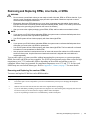
RPMs
The E1200 system requires the installation of at least one RPM, although two are recommended for
redundancy. RPMs are designed to be installed in either the center R0 or R1 slots. Since FTOS searches
for an RPM in slot 0 first, Force 10 recommends you install your RPM in slot 0 when only running with
one RPM. Do not force RPMs into line card slots. RPMs are keyed differently than line cards to prevent
improper installation.
The E1200 system requires the installation of at least one RPM, although two are recommended for
redundancy. RPMs are designed to be installed in either the R0 or R1 slots. Do not force RPMs into line
cards slots. RPMs are keyed differently than line cards to prevent improper installation.
You can hot-insert a second RPM into a running system without performance interruption or software
intervention. A second RPM for redundant functionality provides uninterrupted operability if the system
transitions from the active RPM to the standby RPM. The standby RPM constantly performs updates and
receives the same configuration information received by the active RPM. The standby RPM also
performs diagnostics on its subsystems. In the event of a failover, the standby RPM immediately takes
over and resumes the control activities that the active RPM was performing. Installing a Second RPM on
page 44 provides more information on the second RPM.
The RPM Major and Minor alarm LEDs are controlled by software which sets the threshold levels for
triggering the different stages of alarms.
Line Cards
Your E1200 configuration requires a minimum of one line card. Line cards are hot-swappable. The line
card ports provide external interface functions for connections to other systems (for example, a router or
switch). Each line card has an onboard CPU for line card management which updates packet forwarding
information, obtains statistical information, and performs synchronization tasks with the RPM, as well as
Dell Force10 custom-built ASICs, which enable line-rate forwarding.
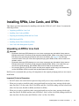
Line Card Port Numbering
There are 14 line card slots available in the E1200 chassis. A minimum of one line card is required for
operation. Line cards are installed in slots 0 through 13. Ports on line cards are numbered from the top,
starting from 0 (see Figure 9-1).
42
|
Installing RPMs, Line Cards, and SFMs
Figure 9-1.
24 Port 1GE and 2-Port 10GE Line Card Port Numbering
24-port 1GE line card
2-port 10GE line card
Port 0
Port 1
Port 2
Port 3
PORT 0
Port 4
FN
Blank Panels
CAUTION: To avoid a chassis over-temperature condition, install blanks for RPMs, SFMs, and line card slots
not in use. Always replace cards or blanks immediately.
Blank panels for RPMs, SFMs, and line cards must be installed in empty slots to control airflow. If a slot
is not filled for more than five minutes, the following message appears on the console:
%CHMGR-2-MINORTEMP: Minor alarm: chassis temperature high (SFM temperature reaches or
exceeds threshold of 65C)
Blank panels are shipped with the system to ensure that all chassis slots are installed with operational
modules or blanks.
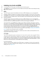
Preparing and Installing RPMs and Line Cards
To prolong the life of the EMI seals, begin installing cards in the right-most slot (slot 13), filling the slots
leftward (slot 12, then slot 11, then slot 10, and so on).
Installing an RPM into the E1200i RPMs, line cards, and blank panels are packaged in the same box. To prolong
the life of the EMI seals, begin installing cards in the right most slot (R1), filling the slots leftward (R0,
then slot 6, then slot 5, and so on).
Installing RPMs, Line Cards, and SFMs
|
43
www.dell.com | support.dell.com
Installing Cards into the E600i
Figure 9-3.
RPM and Line Card Slot Numbering Label
FN00036CH
Figure 9-2.
Slot
FN00029B
Load first
CAUTION: It is important that you retain the packaging and installation order of the cards. Install cards from
right to left, beginning with R1 slot.
To install line cards and RPMs:
Step
Task
1
Remove the line card from its box and carefully remove the line card from the anti-static packaging.
2
Align the RPM with the guide and gently slide it into the slot until you feel the connectors engage with the chassis
backplane.
NOTE: Hold the card by the edges. Avoid touching the printed circuit board and connector pins. Extend the
top and bottom card levers before you insert the card into the slot.
3
Remove the card from the box. Remove the card from the anti-static bag.
4
Rotate the levers to seat the backplane connectors and line card in place.
5
Secure card and blanks in place by tightening the top and captive screws on each card.
6
Follow the same installation procedure for the remaining cards and slots, in the appropriate order.
NOTE: The blank panels do not have board components or connector pins. Align the blank with the guides
and gently slide toward the backplane.
Installing a Second RPM
NOTE: If your system contains two RPMs, both RPMs must contain the same software image.
44
|
Installing RPMs, Line Cards, and SFMs
Install a second RPM either before the system is powered on or after the Primary RPM is up and stable.
After the second RPM is installed, wait several seconds until the connection between the two RPMs is
established before configuring any commands. Below is an example of the messages that should appear:
%POLLMGR-2-ALT_RPM_STATE: Alternate RPM is present
%IRC-6-IRC_COMMUP: Link to peer RPM is up
%RAM-6-RAM_TASK: RPM1 is in Standby State.
Once the link between the two RPMs is established, copy the running configuration to the startup
configuration.
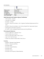
RPM Label and LEDs
Table 9-1 describes the RPM LED states and the RPM front panel.RPMs control the routing and
switching functions for the entire E1200 system. The E1200 operates with a minimum of one RPM
module. You can hot-insert a second RPM into a running system without performance interruption or
software intervention. A second RPM for redundant functionality provides uninterrupted operability if
the system transitions from the primary RPM to the secondary (standby) RPM. The secondary RPM
constantly performs updates and receives the same information received by the primary RPM. The
secondary RPM also performs diagnostics on its subsystems. In the event of a switchover, the secondary
RPM immediately takes over and resumes the control activities that the primary RPM was performing.
Table 9-1.
RPM LEDs
Section
Label
Description
Management
10/100
Ethernet
L: Green: link is up
A: Green: activity on port
Alarms
Major
Red: a critical condition exists, such as a severe over temperature condition, a fan tray
failure, an overcurrent condition in a power supply, or an out-of-tolerance voltage.
The RPM LEDs are controlled by software which sets the threshold levels for triggering the
different stages of alarms.
Unlit: no major conditions
Minor
Amber: a serious condition exists, such as an over temperature condition, a single fan failure,
or a line card failure. The RPM LEDs are controlled by software, which sets the threshold
levels for triggering the different stages of alarms.
Unlit: no minor alarm conditions
ACO/LT
Allows you to test the operability of LEDs to verify that they are able to light.
Press the ACO/LT button to temporarily illuminate the LEDs on the RPM.
If you press this button when the alarm status LED is lit, the alarm relay contacts are reset
until the next alarm event.
Installing RPMs, Line Cards, and SFMs
|
45
www.dell.com | support.dell.com
Table 9-1.
RPM LEDs
Flash
In Use
Green: flash memory card is in the process of a read or write process. Do not remove the
flash card when the In Use LED is lit.
Unlit: not in use
Primary
Green: primary
Unlit: secondary (or standby)
Status
This is a bi-color LED.
Green: operational
Amber: fault detected
Flashing green: booting
Unlit: in secondary mode or power is off
Line Card LEDs
Line card LEDs are described in the documentation specific to each line card. Refer to the installation
documentation that came with the card for to understand LED appearance and meaning.
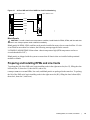
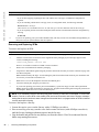
Installing Switch Fabric Modules (SFMs)
A minimum of eight SFMs are required in order for the E1200 system to operate properly. Slot 9 allows
for a redundant SFM, allowing up to ten SFMs in the E1200i system.
SFMs carry user traffic between line cards or between RPMs and a line card. SFMs plug directly into the
backplane, which provides high-speed access to the line cards. The switch fabric receives user data
packets and redirects them to the appropriate destinations according to the routing information.
CAUTION: If you are not operating your system with a redundant (tenth) SFM, you must install an SFM blank
to avoid overheating and ensure EMI containment.
Install SFMs from the right-most slot (9) to the left-most slot (0).
Step
Task
1
Remove an SFM from the anti-static packaging.
2
Align the SFM with the guide and gently slide it into the slot until you feel the connectors engage with the chassis
backplane.
Note: Hold the SFM by the edges. Avoid touching the printed circuit board and connector pins. Extend the top
and bottom card levers before you insert the card into the slot.
3
Rotate the lever to seat the backplane connectors and card in place.
4
Secure each SFM in place by tightening the captive screw.
5
Continue the process for the remaining SFMs.
6
Align any blank panels with the guides and gently slide toward the backplane. Secure each blank panel by
tightening the single captive screw.
NOTE: If you are not operating your E1200 system with redundancy, your SFM package will include blank
panels. Blanks are slot covers that have no board components or connector pins.
46
|
Installing RPMs, Line Cards, and SFMs
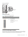
Figure 9-4.
Installing SFMs
Start with slot 8
or slot 9
FN00036CH
SFM Front Panel and LEDs
Table 9-2 illustrates the SFM front panel and LEDs.
Table 9-2.
SFM Front Panel and LED Descriptions
CC-E-SFM3
Active
Status
LED
Description
Active
Green: active and passing traffic
Unlit: in standby mode
Status
Flashing Green: booting
Green: operational
Flashing Amber: communication failure
Amber: fault detected
Unlit: no power
Switch Fabric
Assy
Serial
Line Card Cable Management Systems
Dell Force10 provides a variety of E1200 chassis cable management systems to manage your fiber optic
and auxiliary cables connecting to line cards. For details, see the Dell Force10 price list. For installation
instructions, see the instructions that come with the specific cable management system.
Installing RPMs, Line Cards, and SFMs
|
47
www.dell.com | support.dell.com
48
|
Installing RPMs, Line Cards, and SFMs
10
RPM Ports and Cables
This chapter describes standard RPM cables and adapter pin assignments for the E1200i AC and DC
systems. It contains the following sections:
• RPM Ports
• Cable and Adapter Pin Assignments
• Accessing the 10/100 Ethernet Management Port
This section provides the following:
• RPM Ports
• Cable and Adapter Pin Assignments
• Accessing the 10/100 Ethernet Management Port
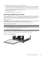
RPM Ports
There are three ports on the RPM. They are labeled and described as:
• Console. A Universal Asynchronous Receiver/Transmitter (UART) port with an RJ-45 jack, is used for
system configuration and monitoring. Modem connections are not supported on this port.
• Auxiliary. A UART port with an RJ-45 jack, allows modem access to the E1200 system from a remote
location.
• 10/100 Ethernet. A 10/100 Ethernet port is the Management port, which is a channel to download
images and manage the system, as well as FTP and Telnet operations. You must provide a RJ-45
Ethernet cable to connect to the Ethernet receptacle.
Connecting the Console and Auxiliary Ports
NOTE: Attach an ESD-preventive wrist strap and connect the leash to the ESD connection on the front of the
E1200 chassis. Always wear an ESD-preventive wrist or foot-heel ground strap when handling components.
NOTE: Always wear an ESD-preventive wrist or foot-ground strap when handling components.
The console and auxiliary ports are asynchronous serial ports. If you connect a device to these ports, it
must be capable of asynchronous transmission. Your terminal or terminal emulation mode must be set to
VT100 with the following settings:
• 9600 baud rate (to avoid autobaud input, the default is set to a 9600 bps baud rate)
• No parity
RPM Ports and Cables
|
49
www.dell.com | support.dell.com
• 8 data bits
• 1 stop bit
• Window Terminal Emulator option set to NO
• 24 lines X 80 characters
• No flow control (console port only)
• Hardware flow control (RTS/CTS) (for auxiliary port only)
Cable and Adapter Pin Assignments
Use the E1200 Console port on the RPM to connect to a terminal port, PC serial port, or a terminal server
to configure and monitor your system. Use the E1200 Auxiliary port on the RPM to connect to a modem.
Both the Console and Auxiliary port are RJ-45 ports. Figure 10-1 displays the pinouts in an RJ-45 port.
Figure 10-1.
Pinout for an RJ-45 Connector End Adaptors
87654321
Table 10-1 displays the RJ-45 console port pin assignments. Table 10-2 displays the RJ-45 auxiliary port
pin assignments.
Table 10-1.
Pin
Signal
Input/Output
1
NC (unused)
-
2
DTR
Output
3
TxD
Output
4
GND
-
5
GND
-
6
RxD
Input
7
DSR
Input
8
NC (unused)
-
Table 10-2.
50
|
Console Port (RJ-45) Pin Assignments
Auxiliary Port (RJ-45) Pin Assignments
Pin
Signal
Input/Output
1
RTS
Output
2
DTR
Output
3
TxD
Output
4
GND
-
RPM Ports and Cables
Table 10-2.
Auxiliary Port (RJ-45) Pin Assignments
Pin
Signal
Input/Output
5
GND
-
6
RxD
Input
7
DSR
Input
8
CTS
Input
Accessing the Console with a DB-9 Adapter
You can connect to the console using a RJ-45 to RJ-45 rollover cable and a RJ-45 to DB-9 female DTE
adapter (labeled “TERMINAL”) to a terminal server (for example, PC). Table 10-3 lists the pin
assignments.
Table 10-3.
Pin Assignments Between the E1200 Console and a DTE Terminal Server
E1200 Console
Port
Signal
RJ-45 to RJ-45 Rollover Cable
RJ-45 to DB-9
Adapter
Terminal Server
Device
RJ-45 pinout
RJ-45 Pinout
DB-9 Pin
Signal
RTS
1
8
8
CTS
DTR
2
7
6
DSR
TxD
3
6
2
RxD
GND
4
5
5
GND
GND
5
4
5
GND
RxD
6
3
3
TxD
DSR
7
2
4
DTR
CTS
8
1
7
RTS
Accessing the Console with a DB-25 Adapter
You can connect to the console using an RJ-45 to RJ-45 rollover cable and RJ-45 to DB-25 female DTE
adapter. Table 10-4 lists the pin assignments.
Table 10-4.
Pin Assignments Between E1200 Console and DB-25 Adapter
E1200 Console
Port
Signal
RJ-45 to RJ-45 Rollover Cable
RJ-45 to DB-25
Modem Adapter
Terminal Server
Device
RJ-45 Pinout
RJ-45 Pinout
DB-25 Pinout
Signal
RTS
1
8
5
CTS
DTR
2
7
6
DSR
TxD
3
6
3
RxD
GND
4
5
7
GND
GND
5
4
7
GND
RxD
6
3
2
TxD
RPM Ports and Cables
|
51
www.dell.com | support.dell.com
Table 10-4.
Pin Assignments Between E1200 Console and DB-25 Adapter (continued)
E1200 Console
Port
Signal
RJ-45 to RJ-45 Rollover Cable
RJ-45 to DB-25
Modem Adapter
Terminal Server
Device
RJ-45 Pinout
RJ-45 Pinout
DB-25 Pinout
Signal
DSR
7
2
20
DTR
CTS
8
1
RTS
Accessing the Auxiliary Port by Modem
You can access the auxiliary port using a dial-up modem using an RJ-45 to RJ-45 rollover cable and RJ45 to DB-25 male DCE adapter (labeled “MODEM”). Table 10-5 lists the pin assignments.
Table 10-5.
RJ-45 to DB-25 Adapter Pin (Modem) Assignments
E1200 Auxiliary
Port
Signal
RJ-45 to RJ-45 Rollover Cable
RJ-45 to DB-25
Modem Adapter
Modem
RJ-45 Pinout
RJ-45 Pinout
DB-45 Pinout
Signal
RTS
1
8
4
RTS
DTR
2
7
20
DTR
TxD
3
6
3
TxD
GND
4
5
7
GND
GND
5
4
7
GND
RxD
6
3
2
RxD
DSR
7
2
8
DCD
CTS
8
1
5
CTS
Accessing the 10/100 Ethernet Management Port
Configure the 10/100 Ethernet management port, labeled 10/100 Ethernet on the primary RPM card in
order to obtain network access capability, such as downloading a runtime image onto your system. You
can connect this port to an Ethernet hub or FastEthernet port on a router.
Table 10-6.
52
|
10/100 Ethernet Management Port LEDs
Label
Description
L (Link)
Lit: Link is up
Unlit: No connection
A (Activity)
Lit: Activity on port
Unlit: No activity
RPM Ports and Cables
11
Powering Up
This chapter provides instructions for powering up your E1200 AC or DC system after you have installed
all the chassis components and made your power and network connections. It covers the following topics:
• Preparation
• Supplying Power - AC
• Supplying Power - DC
• Booting to the CLI Prompt
Preparation
NOTE: Make sure that the switch on the remote power source is in the OFF position until you are ready to
supply power to the chassis.
Before you supply power to your chassis, Dell Force10 recommends that you re-inspect your equipment
rack and chassis.
Verify that:
• The equipment rack is properly secured and grounded.
• The chassis is bolted and secured into your equipment rack.
• The chassis is grounded.
• Each power supply module is properly installed and secured.
• The AC-Cord Retainer is installed, if applicable (AC systems).
• The power switch is in the OFF position, if applicable (DC systems).
• Power cables connect to a compliant remote power source.
• Both fan trays are installed and secured.
• All line cards, RPMs, and SFMs are properly installed and secured.
• All chassis slots are filled. Blank panels and covers are installed in all empty slots.
WARNING: Leakage Current (High Touch Current): The AC power cords are secured to the power inlet using
the provided bracket. The power cord plugs must be secured to the building outlets by the chassis installer or
a qualified electrician.
Powering Up
|
53
www.dell.com | support.dell.com
Supplying Power - AC
Step
Task
1
Flip the REMOTE power switch to the ON position.
2
Remove the card from the box. Remove the card from the anti-static bag.
3
Flip the On/Standby switch to the ON position.
4
The Status LED for each power supply should be green (online). If a power supply’s LED is not lit or is amber:
• ensure that the unit is properly installed.
• Verify the power source.
• If the power supply’s LED remains unlit, power off the remote power source and replace the unit.
Both fan tray LEDs should be green (online). Verify that air is flowing through the chassis. If a fan tray is not
operating properly or air is not flowing through the chassis:
5
• power off the chassis at the remote power source.
• Ensure that the fan tray is properly installed.
• Verify the power source.
• If the fan tray LED remains unlit on power-up, replace the fan tray.
To turn the chassis power off, flip the On/Standby switch to the Standby position.
NOTE: The AC power supplies status LEDs will remain lit and the power supply fans will continue to operate,
even though DC power to the backplane has been turned off.
Supplying Power - DC
Step
Task
1
Flip the REMOTE power switch to the ON position.
2
Remove the card from the box. Remove the card from the anti-static bag.
3
The Status LED for each power supply should be green (online). If a power supply’s LED is not lit or is amber:
• ensure that the unit is properly installed.
• Verify the power source.
• If the power supply’s LED remains unlit, power off the remote power source and replace the unit.
4
Both fan tray LEDs should be green (online). Verify that air is flowing through the chassis. If a fan tray is not
operating properly or air is not flowing through the chassis:
• power off the chassis at the remote power source.
• Ensure that the fan tray is properly installed.
• Verify the power source.
• If the fan tray LED remains unlit on power-up, replace the fan tray.
Booting to the CLI Prompt
After you supply power to the system, the following should occur:
• During bootup, power is removed temporarily from all line cards and SFMs. This is expected behavior.
• Both fan trays should be operating.
54
|
Powering Up
• The green (online) LEDs for the fan trays, Power Supplies, RPMs, SFMs, and line cards should be lit
and remain lit as long as the system is receiving power and is operational.
• The fans should be operating.
• The green (online) fan tray, power module, RPM, SFM, and line card LEDs should be lit and remain lit
as long as the system is receiving power and is operational.
When you supply power to the E1200 system, the system performs a series of power-on self tests. RPM,
line card, and SFM LEDs blink as the diagnostic programs run. No user interaction is required at this
point. Observe the process on your console monitor. When the boot process is complete, the card LEDs
remain online (green) and the console monitor displays the Command Line Interface (CLI) prompt.
NOTE: Do not press any keys or control sequences at any time during the boot process. Doing so may cause
the boot process to terminate.
Refer to the <ItalicText>FTOS Configuration Guide, on the technical publications CD-ROM, for initial
configuration procedures and configuration instructions.
Booting from the BOOT_USER Prompt
The initial boot operation automatically brings up the system to the runtime CLI. To interrupt the
automatic boot process, issue a break key sequence (CNTL^). The console monitor will display the
default BOOT_USER # prompt. Refer to Appendix B, System Boot, on page 69 for instructions to
continue the boot process.
Powering Up
|
55
56
|
Powering Up
www.dell.com | support.dell.com
12
Removing and Replacing Components
This chapter provides instructions for removing and replacing E1200 AC and DC components. It covers
the following topics:
• Removing and Replacing Fan Trays
• Removing and Replacing AC Power Supplies
• Removing and Replacing DC Power Supplies
• Removing and Replacing RPMs, Line Cards, or SFMs
• Removing and Replacing the Air Filter
When a component fails, the E1200 system triggers major or minor alarm LEDs (located on the RPM),
sends events to the SNMP trap and show alarms table, disables or changes component Status LEDs or
triggers an audible alarm. Refer to Appendix C, Alarms, on page 75 for more information on alarms.
Removing and Replacing Fan Trays
In the event of a fan tray failure, signified by an amber LED, an SNMP trap, or major alarm event, the
entire fan tray must be replaced. If one or more fans within a fan tray fail, the system generates a minor
alarm and an SNMP trap.
The fan trays are hot-swappable.
To remove and replace the fan tray, you must have access to the rear of the chassis and be able to pull the
fan tray completely out of the slot (at least 20 inches).
To remove and replace a fan tray:
Step
Task
1
Prior to removing a fan tray, turn the screw latch counter-clockwise (with a flathead screwdriver) one quarter of a
turn to unlock the fan tray. (Figure 12-1).
2
Grip the handle and pull the fan tray out approximately one inch from the chassis. Wait 30 seconds until the fan
blades stop rotating, then remove.
WARNING: Keep fingers clear of rotating fan blades.
3
Prior to inserting a new fan tray, fully turn (with a flathead screwdriver) the screw latch counter-clockwise until
the fan tray latching mechanism retracts into the fan tray.
4
Insert the fan tray into the chassis. Guide the tray firmly into the slot until it stops and the handle end is flush with
the chassis rear.
5
To secure the fan trays into place, turn the screw latch clockwise to tighten the latching mechanism. (see
Figure 12-1)
Removing and Replacing Components
|
57
www.dell.com | support.dell.com
Figure 12-1.
Securing the Fan Tray Screw Latch
screw latch
Removing and Replacing AC Power Supplies
If you are operating your E1200 AC chassis with redundant Power Supplies, you can install, remove, or
replace a Power Supply without affecting system operation. If you are operating your E1200 AC system
with only two Power Supplies (the minimum), you must completely power off the system.
NOTE: If there is a Power Supply failure (Power Supply LED is not lit or major alarm LED is lit), the entire
Power Supply Module must be replaced. There are no field serviceable parts inside the Power Supply unit.
WARNING: Do not remove the AC-Cord Retainer until the power supplied by the remote power source is
OFF.
WARNING: Do not remove the AC-Cord Retainer until the power supplied by the remote power source is
OFF.
NOTE: The On/Standby switch disconnects power to the rest of the chassis from all 6 AC power supplies.
•
When the AC cord is attached, power supply fans will spin and the LEDs will indicate status while the On/
Standby switch is in Standby.
NOTE: AC Power Supplies may be replaced without removing the AC-cord retainer or the AC cords.
58
|
Removing and Replacing Components
Remove an AC Power Supply in a non-redundant installation
Step
Task
1
Unplug the network interface cables connected to the line card or RPM.
2
Activate the disconnect switch at the Main power source or disconnect the AC cord at the remote power source.
3
Grip the handle and squeeze the thumb latch.
4
Slide the Power Supply out of the slot.
5
If you are replacing the Power Supply, go to Installing AC Power Supplies on page 29.
Remove an AC Power Supply in a redundant installation
Step
Task
Power Supplies
AC Power Plugs
WARNING HIGH LEAKAGE CURRENT. EARTH CONNECTION
ESSENTIAL BEFORE CONNECTING SUPPLY.
COURANT DE FUITE ELEVE. RACCORDEMENT
A LA TERRE INDISPENSABLE AVANT LE
RACCORDEMENT AU RESEAU.
On/Standby
Switch
/
/
\
/
AC-Cord Retainer
Safety Cover
This retainer must be in place during normal operation.
Do not remove except for servicing
1
Tilt the AC-cord Retainer Safety cover approximately 15o and gently slide the cover away from the chassis.
2
Grip the handle and squeeze the thumb latch.
3
Slide the Power Supply out of the slot.
4
If you are replacing the Power Supply, go to Installing AC Power Supplies on page 29.
Removing and Replacing DC Power Supplies
If you are operating your E1200 DC chassis with redundant Power Supplies, you can install, remove, or
replace a Power Supply without affecting system operation. If you are operating your E1200 DC system
with only one Power Supply (the minimum), you must completely power off the system.
NOTE: If there is a Power Supply failure (Power Supply LED is not lit or major alarm LED is lit), the entire
Power Supply Module must be replaced. There are no field serviceable parts inside the Power Supply unit.
Removing and Replacing Components
|
59
www.dell.com | support.dell.com
Remove a DC Power Supply
Step
1
Task
Ensure that the remote power source is in the OFF position and that the PEM status light is off.
• PEM 0 connects to remote power source 0.
• PEM 1 connects to remote power source 1.
2
Loosen the retaining screw and remove the PEM safety cover.
R etaining
s crew
S afety
cover
FN00103lp
3
Switch the Over Current Protector (located on the PEM front panel) to the OFF position.
Studs
PEM interlock
lever
Over-current protector
Latch Release
Status
-48/-60Vdc
150A, 7200VA
CC-E1200-PWR-DC
60
|
FN00102lp
Locking screws
4
Loosen the Locking screws.
5
Lift and hold the PEM interlock lever to release the PEM
6
While holding the interlock lever up, using the bottom handle, pull the PEM straight out of the slot.
Removing and Replacing Components
Removing and Replacing RPMs, Line Cards, or SFMs
WARNING:
•
•
•
Do not remove a panel blank unless you are ready to install a line card, RPM, or SFM into that slot. If you
remove a card, immediately replace the empty slot with a panel blank. Blanks are required to control
airflow and electromagnetic interference.
Electrostatic discharge (ESD) damage can occur when components are mishandled. Always wear an
ESD-preventive wrist or foot-heel ground strap when handling RPMs, SFMs, or line cards. (Connect the
ESD strap to the grounding plug located on the front of the chassis.)
After you remove the original packaging, place RPMs, SFMs, and line cards on an antistatic surface.
NOTE:
•
•
If you operate your E1200 without redundant RPMs, the system enters a software-defined power-down
state when you remove the only RPM for replacement.
Your E1200 system will not function properly with fewer than eight SFMs.
NOTE:
•
•
•
If you operate your E1200 without redundant RPMs, the system enters a software-defined power-down
state when you remove the only RPM for replacement.
Your E1200 system will not function properly with fewer than eight SFMs. The line cards will not forward
information to a non-operational or absent SFM.
Use the optical connector insertion/removal tool to insert and remove fiber cables from 1GE cards with
small form factor ports. A optical Connector insertion/removal tool is shipped with each card that is
ordered separately.
You can add, replace, or remove modules without interrupting the system power or system operations.
RPMs, line cards, and SFMs are hot-swappable. The E1200 system generates major alarm events for high
temperatures (over 75°C) and module failures depending on the module and whether or not it is
redundant. Minor alarms are generated for component temperatures over 65°C and 75°C for line cards.
SNMP traps are sent for both alarm types. Refer to Appendix C, Alarms, on page 75 for more details.
Removing and Replacing line cards or RPMs
To remove and replace E1200 line card or RPM modules:
Step
Task
1
Unplug the network interface cables connected to the line card or RPM.
2
Loosen the captive screws and pull the ejector levers simultaneously toward you to disengage the backplane
connections.
3
Slide the card out of the slot and store the cards in the original antistatic packaging.
4
If you are immediately installing a replacement card, align the new card with the guide, and gently slide the card
into the slot until you feel the connectors engage with the chassis backplane.
If you are not planning to install a new card immediately, install a blank panel.
Removing and Replacing Components
|
61
www.dell.com | support.dell.com
Step
Task (continued)
If you are installing a line card, follow these procedures:
5
• If you are hot-swapping (replacing the line card with the same card type), no additional configuration is
required.
• If you are installing a different line card type, enter, in Configuration mode, the following command:
linecard number card-type,
where number is a slot number from 0 to 13, and card-type is the five-character code for the card type.
• If you are replacing the line card with a blank panel, delete the line card information from the configuration by
entering:
no linecard
If you are not operating your system with redundant cards (with only one line card, one RPM, and eight SFMs) you
must power off your system until the cards are replaced.
6
Removing and Replacing SFMs
To remove and replace an SFM:
Step
Task
1
Loosen the captive screw and pull the ejector lever towards you to disengage the backplane connections.
2
Slide the card out of the slot and store in the original anti-static packaging. System messages appear on the
console, including the following:
%TSM-6-SFM_REMOVE: Removed SFM
Wait 5 to 10 seconds to install a new SFM or reinsert an SFM. *
3
Remove the new SFM from the antistatic packaging.
4
Align the new SFM with the guide and gently slide the card into the slot until you feel the connectors engage with
the chassis backplane.
Note: Hold the SFM by the edges. Avoid touching the printed circuit board and connector pins. Extend the card
lever before you insert the card into the slot.
5
Rotate the lever to seat the backplane connectors and SFM in place.
6
Secure the SFM in place using the provided screw.
7
If you are not operating your E1200 system with redundancy, replace the empty slot with a filler panel blank.
Blanks do not have board components or connector pins. Align the blank with the guides and gently slide toward
the backplane. Rotate the lever to secure the blank in place.
NOTE: If you mistakenly insert an SFM too quickly after removing it, traffic flow is interrupted. To correct the
situation, remove an active SFM or the standby SFM, wait several seconds, and reinsert. System messages
stating that the active interfaces’ status changed and the switch fabric is up appear when an SFM is inserted
correctly and traffic is flowing.
To remove and replace a fan tray:
Loosen the captive screws on the fan tray with a #2 Phillips screwdriver.
2 Prior to removing a fan tray, turn the screw latch counter-clockwise (with a Phillips screwdriver)
until the fan tray latching mechanism retracts into the fan tray.
3 Grip the handle and pull the fan tray halfway out from the chassis. Wait 30 seconds until the fan
blades stop rotating then remove.
1
62
|
Removing and Replacing Components
NOTE: Always keep your fingers away from rotating blades.
5 Prior to inserting the fan tray replacement, turn the screw latch counter-clockwise (with a Phillips
screwdriver) until the fan tray latching mechanism retracts into the fan tray. Insert the fan tray into
the chassis at a slightly upward angle. Guide the tray firmly into the slot until you feel the connectors
engage with the chassis backplane. Release the screw latch.
6 Tighten the captive screws.
7 Verify that the fan tray LED is lit green (online).
4
Removing and Replacing the Air Filter
A factory-installed air filter (Figure 12-2) is shipped with the E1200 system. The hot-swappable air filter
prevents large particles, debris, and dust from entering and circulating through the system, and ensures
proper air flow through the system. Filters should be inspected monthly and replaced every twelve
months or as required.
WARNING: An improperly installed air filter will restrict air flow and will generate thermal problems throughout
the chassis. Ensure the air filter is oriented correctly and seated securely in the slot.
Do not operate without a filter for any longer than 30 minutes to avoid card over-temperature conditions.
To remove and replace the air filter:
Step
Task
1
Pull the air filter straight out of the chassis.
2
Rotate the replacement filter so that the front handle label is right reading.
3
Guide the filter firmly into the slot until it stops.
The E1200 air filter is hot-swappable. You do not need to turn the power off to the chassis to replace a
filter. Filters should be inspected monthly and clean and replaced every six months.
Figure 12-2.
Replacing the Air Filter
FN
Removing and Replacing Components
|
63
www.dell.com | support.dell.com
64
|
Removing and Replacing Components
A
Using a Flash Memory Card
This appendix provides information about using an external flash memory card and contains the
following sections:
• External Flash Memory Card Overview
• Inserting the External Flash Memory Card
• Removing the External Flash Memory Card
• Formatting an External Flash Card
• Copying Files to the External Flash
• Displaying Files Stored on the External Flash
• External Flash Memory Card Overview
• Formatting an External Flash Card
• Inserting the External Flash Memory Card
• Removing the External Flash Memory Card
• Copying Files to the External Flash
• Displaying Files Stored on the External Flash
External Flash Memory Card Overview
Each RPM card is designed with a slot to accommodate an external flash memory card (slot0:). You can
use a flash card to copy the image and configuration files for storage and backup purposes. For complex
configurations, use the copies for other E1200 systems in your network. Configure your boot execution
process to use the images stored on a flash card as the primary (active), secondary (standby), or default
boot order preference. Optional external flash memory cards are shipped blank.
Inserting the External Flash Memory Card
NOTE: Only insert the external flash before system boot or after the system has completed its boot and is runtime mode.
Using a Flash Memory Card
|
65
Step
Task
1
Press the ejector button to ensure it is in the extended position.
Hold the flash card vertically (with the manufacturer’s label on
the left and the barcode on the right).
2
Gently insert the flash card into the primary RPM flash slot
until the card is flush with the front panel. Do not force the
flash card into the slot.
3
The In Use LED illuminates only during read or write
operations.
FN
www.dell.com | support.dell.com
To install the flash memory card:
To install the flash memory card:
Hold the flash card vertically with the slanted edge on top and the connector end facing the slot.
2 Insert the flash card into the primary RPM flash slot until the card is completely seated with the
connectors at the rear of the slot. Do not force the card into the slot. The slot is specifically tooled to
prevent improper installation.
3 The In Use LEDs only illuminate during read or write operations.
1
Removing the External Flash Memory Card
To remove the flash memory card:
Step
Task
1
Gently depress the flash card in the slot. The card should partially pop out of the slot.
2
Remove the card and place it in an antistatic bag.
To remove the flash memory card:
Gently depress the flash card in the slot. The card should partially pop out of the slot.
2 Remove the card and place it in an antistatic bag.
1
Formatting an External Flash Card
New external flash cards must be formatted in the E1200 before use.
Flash cards used on systems other than the E1200 as well as cards formatted on PCs must be reformatted
in the E1200 flash slot before they can be used. Similar to formatting a new diskette, formatting erases all
information stored on the flash card.
66
|
Using a Flash Memory Card
To format the flash card:
Step
Task
1
Insert the flash card into the flash slot on the primary RPM.
2
In the EXEC CLI mode, enter format slot0:
3
The formatted flash card is ready to use.
Insert the flash card into the flash slot on the primary RPM.
2 In the EXEC CLI mode, enter format slot0:
3 The formatted flash card is ready to use.
1
Copying Files to the External Flash
Copy files to the flash when you want keep a backup image. The In Use LED illuminates during a read or
write operation. Do not eject the flash card from the slot while this LED is lit.
To copy files to the external flash card use the following command:
Command Syntax
Command Mode
Purpose
copy file-url1 file-url2
EXEC Privilege
Configure the following parameters:
• file-url1: the file source
• file-url2: enter slot0://
Displaying Files Stored on the External Flash
Flash cards can be used to copy and store system images, boot images, and configuration files. Optional
flash memory cards are shipped blank.
To display files stored on a flash, use the following command:.
Command Syntax
Command Mode
Purpose
dir [filesystem]
EXEC Privilege
Configure the following optional parameters to view files on
the flash card:
• filesystem: enter either flash: for the internal flash or
slot0: for the external flash.
The default is flash: (the internal flash). To view the external
flash, enter dir slot0:
Figure A-1.
dir Command Example
Force10#dir slot0:
Directory of slot0:
1
-rwx
6478482
Sep 7 101 16:54:34
E1200i.BIN
Using a Flash Memory Card
|
67
www.dell.com | support.dell.com
68
FTOS supports up to a 40-character file name length, up to a 180-character local file path length, and up
to a 256-character remote file path length.
|
Using a Flash Memory Card
B
System Boot
This appendix provides instructions to boot the E1200 AC and DC system from the BOOT_USER
prompt.Dell Force10
The System Boot Process
System Boot
When you supply power to the E1200 system, the system performs a series of power-on self-tests. RPM,
and line card Status LEDs blink during initialization. No user interaction is required as long as the boot
process proceeds without interruption. Observe the process on your console monitor and note the
message output on the display. When the boot process is complete, the RPM and line card Status LEDs
remain online (green) and the console monitor displays the command line interface (CLI) prompt,
Force10>.
The RPM cards in the E1200 system contain an internal flash memory card (flash:). This is the default
storage area for the boot files and the startup configuration file. Upon system power up or a system reset,
the boot process uses parameters stored in non-volatile random access memory (NVRAM) to boot the
system.
Each RPM card is equipped with a slot for an external flash memory card (slot0:). You can copy the
image files and configuration files to the external flash device on the primary RPM. You can also begin
your boot process by accessing a remote server containing the boot image and system image files. When
you configure your system to boot, you can specify the boot preference order: primary, secondary, or
default in the BOOT_USER mode and the CLI mode.
NOTE: The E1200 system supports up to a 40-character file name length, up to a 180-character local file path
length, and up to a 256-character remote file path length.
For information about the flash memory card, refer to Appendix A, Using a Flash Memory Card, on page
65.
Booting from the BOOT_USER Prompt
To get into the BOOT_USER mode, you can issue a break control sequence (CNTL^ ) to interrupt the
automatic boot process or if you experience boot problems. This mode allows you to modify the
parameters necessary to manage the boot process. Only console port access is enabled for the
BOOT_USER mode.
System Boot
|
69
www.dell.com | support.dell.com
To configure the chassis from the BOOT_USER prompt:
Step
1
Command
help
or
?
Task
• The BOOT_USER # prompt appears after an autoboot interruption. This is
the default boot prompt, not the CLI prompt.
• Enter help or ? to display a list of available commands and syntax.
• Enter syntax help to display syntax information and variable descriptions.
• On some display output, you are given the option to continue the help screen
display <cr> or to stop <q>.
• You can abbreviate the boot commands by entering only the first letter of a
command word. A matching algorithm displays the commands starting with
the letter or letters you entered. For example, b displays the commands
starting with the letter b, boot change and boot selector. Entering s h
displays the syntax help information.
• All commands are case insensitive.
2
Execute the following show commands to display important boot information:
show boot selector
This command displays the boot ROM image currently selected and the most recently booted ROM image.
BOOT_USER # show boot selector
ROM BOOTSTRAP SELECTOR PARMETERS:
================================
Current ROM bootstrap selector set to Bootflash
70
|
System Boot
Step
3
Command
Task (continued)
show bootflash
This command displays information about the current boot ROM.
BOOT_USER # show bootflash
GENERAL BOOTFLASH INFO
======================
Bootflash Partition A:
Force10 Networks System Boot
Copyright 1999-2007 Force10 Networks, Inc.
ROM Header Version 1.0
Official CP_IMG_BOOT, BSP Release 2.0.0.14
Created Fri Nov
2 18:22:47 US/Pacific 2007
Bootflash Partition B:
Force10 Networks System Boot
Copyright 1999-2007 Force10 Networks, Inc.
4
show bootvar
This command displays the current operating system boot configuration parameters.
BOOT_USER # show bootvar
PRIMARY OPERATING SYSTEM BOOT PARAMETERS:
========================================
boot device
: flash
file name
: /E1200i-x.bin
SECONDARY OPERATING SYSTEM BOOT PARAMETERS:
==========================================
No Operating System boot parameters specified!
System Boot
|
71
www.dell.com | support.dell.com
Step
5
Command
Task (continued)
boot change {primary |
secondary | default}
If your configuration displays no preconfigured operating system boot
parameters, use the boot change command to edit appropriate fields.
• The primary operating system boot parameters are used in the first attempt
to boot the system.
• The secondary operating system boot parameters are used if the primary
operating system boot selection is not available.
• The default operating system boot parameters are used if the secondary
operating system boot parameter selection is not available. The default
parameters always reside on the internal flash device (flash:).
NOTE: These parameters, as well as other boot parameters, can be modified
in the CLI mode.
When you enter the boot change command, you are prompted for a response.
• Enter a new parameter or press the ENTER key (carriage return) to accept
the default parameter.
• Enter . (period) to clear a field.
• Enter - (dash) to edit a field above the current cursor position.
NOTE: When you enter a new parameter that extends beyond 80 characters,
you cannot use the BACKSPACE key to correct any mistakes. If you make a
mistake, you must re-enter the parameter.
BOOT_USER # boot change primary
'.' = clear field;
'-' = go to previous field
boot device
: flash
file name
: /E1200-3.x.bin
BOOT_USER # boot change default
72
|
System Boot
Step
6
7
Command
interface management port
config 100m
interface management port
config 10m
interface management port
config auto-negotiate
interface management port
config no auto-negotiate
interface management port
config full-duplex
interface management port
config half-duplex
interface management port
config show
Task (continued)
• (OPTIONAL) Use these commands to set the speed and duplex settings for
the Management interface.The default setting is full-duplex and autonegotiation.
• Use the interface management port config show command to view the
Management interface’s physical settings.
show interface management
• Use the show interface management ethernet command to display the IP
ethernet
address and network mask of the management Ethernet port.
interface management ethernet ip • If the show command output does not display configured IP address
address ip-address ip-addressinformation, use the interface management ethernet ip address ip-address
mask
ip-address-mask command to set the IP address of the Management Ethernet
port for network (ftp/tftp) operating system boot.
BOOT_USER # show interface management ethernet
No IP address set for interface management ethernet 0/0!
BOOT_USER # interface management ethernet ip address 1.2.3.4 255.255.0.0
Management ethernet 0/0 IP address: 1.2.3.4 255.255.0.0
8
show default-gateway
default-gateway ip-address
(Optional) Use the show default-gateway command to view gateway
information.
If your server is on the same subnet, you do not need to configure a gateway
parameter.
If your server is not on the same subnet, use the default-gateway ip-address
command to set the gateway IP address.
System Boot
|
73
www.dell.com | support.dell.com
Step
Command
Task (continued)
BOOT_USER # show default-gateway
No gateway IP address specified!
BOOT_USER # default-gateway ip 1.2.3.5
Gateway IP address 1.2.3.5
9
dir flash:
dir slot0:
BOOT_USER
Use the dir flash: command to list files stored on the internal flash device.
Use the dir slot0: command to list files stored on the external flash device.
# dir flash:
Displaying files in flash:
size
date
time
name
--------
------
------
--------
11187685
FEB-15-2002
05:37:58
e1200-.bin
11031398
FEB-23-2002
22:42:46
E1200-3.bin
10
reload
Reload software.
The autoboot program initializes and displays self-test results on the console
screen.
NOTE: Do not press break control sequence at any time during the boot/reboot
process. Doing so causes the boot process to terminate.
11
Force10>
When the reboot completes, the CLI defaults to the EXEC mode.
Refer to the FTOS Command Line Interface Reference for CLI configuration procedures and
configuration instructions.
74
|
System Boot
C
Alarms
The E1200 generates major and minor alarms for the following conditions:
• fan trays status
• Power Supply status
• fan tray status
• power supply status
• RPMs status
• high temperature on RPMs
• line cards status
• high temperature on line cards
• SFMs status
• high temperature on SFMs.
A major alarm is any fault that would render the E1200 non-functional.
A minor alarm is any fault that threatens the operation of the E1200.
You can monitor alarm conditions on the E1200 system through the console, LEDs, and audible alarms. If
you configure the SNMP command (snmp-server enable traps envmon), the FTOS also sends an
SNMP trap.
In the E1200 system, alarms are logged for each occurrence, but the system may not send an event log for
multiple occurrences. For example, whenever a module exceeds the shutdown threshold, the module
shuts down. If more than one module exceeds the warning or high temperature thresholds within a five
minute period, the system generates one event for all effected modules, but alarms are logged for each
occurrence. If the modules temperature falls to 5° lower than the warning threshold temperature, the
system clears the alarm and an SNMP trap.
Table C-1.
Alarm Events and Reporting
Module
Alarm Event
Alarm LED
Reported in
event log
Status LED on Audible
Module
Alarm?
Fans
Entire Fan Tray fails
major (red)
major
unlit
yes
1 or 2 individual fans fail
minor (amber)
minor
unlit
no
major (red)
major
unlit
yes
unlit
not reported
unlit
no
Power
Supply
Power Supply input power fail
Power Supply power fails at
boota
Alarms
|
75
www.dell.com | support.dell.com
Table C-1.
Alarm Events and Reporting
Module
Alarm Event
Fan tray
AC Power
Supplies
Line Card
Alarm LED
Reported in
event log
Status LED on Audible
Module
Alarm?
More than one fan within the module major (red)
fails or hardware failure in the
module
major
amber
yes
One fan within the module fails
minor
amber
no
Hardware failure in a non-redundant major (red)
power configuration (3 power
supplies)
major
red or unlit
yes
Hardware failure in a redundant
power configuration (4 power
supplies)
minor (amber)
minor
red or unlit
no
Hardware failure
major (red)
major
amber
no
Exceeds high temperature limit
major (red)
major
unlit
yes
Exceeds warning temperature limit
minor (amber)
minor
green
yes
Individual interface fails
minor (amber)
reported
amberb
no
Exceeds high temperature limit
major (red)
major
unlit
yes
Exceeds warning temperature limit
minor (amber)
minor
green
no
RPM fails but CP is ok
major (red)
major
amber
yes
Exceeds high temperature limit
major (red)
major
unlit
yes
Exceeds warning temperature limit
minor (amber)
minor
green
no
Any card fails
minor (amber)
minor
amber
no
Any card removed
minor (amber)
minor
unlit
no
Exceeds high temperature limit
major (red)
major
unlit
yes
Exceeds warning temperature limit
minor (amber)
minor
green
no
Any card fails
major (red)
major
amber
yes
Any card removed
major (red)
major
unlit
yes
minor (amber)
RPM (Non-redundant Configuration with 1 RPM)
SFMs (Redundant Configuration with 10 SFMs)
8 SFMs (Non-Redundant Configuration)
a. Event appears only in the show alarms command output.
b. The interface’s Link LED is unlit.
Power Supplies and Alarms
If a Power Supply fails while the E1200i is operating, the software generates a major alarm and an SNMP
trap, lights the major LED, and activates the audible alarm.
When a Power Supply fails, the software also records one alarm event for line cards, RPM, and SFM,
though each contains its own power source. The system generates one alarm event and SNMP trap
summarizing the Power Supply failure and the components affected.
76
|
Alarms
AC Power Supplies and Alarms
During system boot, if the redundant power supply (the fourth power supply) is missing or fails, the
FTOS does not generate any alarm messages since the minimum configuration of three power supplies is
operating. Yet, if a fourth AC power supply is installed, and later one of the four power supplies is
removed or fails, the system generates a minor alarm.
If only three power supplies are installed and one of them fails while the E1200 is operating, the software
generates a major alarm and an SNMP trap, lights the major LED, and activates the audible alarm.
When you operate the E1200 with three AC power supplies and six or more line cards, the software lists
a redundancy alarm on the console and in the show alarms command output. All line cards operate
normally.
SFMs and Alarms
The number of SFMs present in the system when it boots determines the level of alarms sent when a tenth
(redundant) SFM is removed or fails. At boot time, if ten SFMs are present and functioning, the E1200
system issues no alarms. However, if one SFM fails or is removed, the system sends a minor alarm
stating that nine SFMs are present. The system requires eight functioning SFMs to pass traffic.
At boot time, if eight SFMs are present and functioning, the E1200 system issues no alarms. The system
issues no alarms if an SFM is added to the system; however, if the number of functioning SFMs changes
from nine to eight, the system sends a minor alarm event. The system always triggers a major alarm when
the number of working SFMs reaches seven.
Alarms
|
77
78
|
Alarms
www.dell.com | support.dell.com
D
System Specifications
This appendix contains two major sections:
• E1200i AC Chassis Physical Design
• E1200i AC System Power Requirements
• E1200i DC Chassis Physical Design
• E1200i DC System Power Requirements
• Environmental Specifications
• Agency Compliance
E1200i AC Chassis Physical Design
Parameter
Specifications
Height
42 inches (106.68 cm)
Width
17.40 inches (44.20 cm)
Depth (without cable management system)
22.25 inches (56.51 cm)
Chassis weight with factory-installed components
(backplane and air filter)
139 pounds (approx.) (63.05kg)
Weight fully loaded (backplane, air filter, 2 fan trays, 10
SFMs, RPMs, and 14 line cards)
394 pounds (approx.) (178.7 kg)
Mounting
Attached rack mount brackets are factory set for front
mounting in a standard 19-inch rack.
Mounting brackets are adjustable for center and rear
mounting.
Optional brackets are available for front or center
mounting in a 23-inch rack or cabinet.
Rack clearance required
Front: 18 inches
Rear: 20 inches
Thermal Output
Maximum for fully loaded chassis
7,784W (26,578BTU/HR)
Minimum for chassis with one 48-port 1GE line card
1,450W (4,951 BTU/HR)
System Specifications
|
79
www.dell.com | support.dell.com
E1200i AC System Power Requirements
Parameter
Specifications
Nominal Input Voltage
200-240 VAC 50.60 Hz
Maximum Power Consumption
5,734 @ 200/240 VAC
Maximum Thermal Output (5,484 W)
18,710 BTU/hour
Maximum Input Current (per power supply)
15.0 A @ 200 VAC
12.5 A @ 240 VAC
Maximum System Power Input
5.8 KVA @ 200/240 VAC
E1200i DC Chassis Physical Design
Parameter
Specifications
Height
36.75 inches (93.35 cm)
Width
17.40 inches (44.20 cm)
Depth (without cable management system)
21.25 inches (53.98 cm)
Chassis weight with factory-installed components
(backplane and air filter)
97 pounds (approx.) (44.00 kg)
Weight fully loaded (backplane, air filter, 2 fan trays, 10
SFMs, RPMs, and 14 line cards)
319 pounds (approx.) (144.70 kg)
Mounting
Attached rack mount brackets are factory set for front
mounting in a standard 19-inch rack.
Mounting brackets are adjustable for center and rear
mounting.
Optional brackets are available for front or center
mounting in a 23-inch rack or cabinet.
Rack clearance required
Front: 18 inches
Rear: 20 inches
Thermal Output
Maximum for fully loaded chassis
6850W (23,389 BTU/HR)
Minimum for chassis with one 48-port 1GE line card
1,450W (4,951 BTU/HR)
E1200i DC System Power Requirements
80
|
Parameter
Specifications
Nominal Input Voltage
-44 to 60 VDC
Maximum Power Consumption
5,210 W
Maximum Thermal Output (4,910 W)
16,924 BTU/hour
Maximum Input Current (per DC PEM)
150 A
System Specifications
Environmental Specifications
Operating
Specifications
Temperature
32° to 104°F (0° to 40°C)
Maximum altitude
No performance degradation to 10,000 feet (3,048 meters)
Relative humidity
5 to 85 percent, noncondensing
Shock
Designed to meet Telcordia GR-63 CORE
Vibration
Designed to meet Telcordia GR-63 CORE
Non-operating
Temperature
-40° to 158°F (-40° to 70°C)
Maximum altitude
15,000 feet (4,572 meters)
Relative humidity
5 to 95 percent, noncondensing
Vibration
Bellcore GR-63
Agency Compliance
The E1200 is designed to comply with the following safety and agency requirements.
USA Federal Communications Commission (FCC) Statement
This equipment has been tested and found to comply with the limits for a Class A digital device, pursuant to Part 15 of the FCC rules. These
limits are designated to provide reasonable protection against harmful interference when the equipment is operated in a commercial
environment. This equipment generates, uses, and can radiate radio frequency energy. If it is not installed and used in accordance to the
instructions, it may cause harmful interference to radio communications. Operation of this equipment in a residential area is likely to cause
harmful interference, in which case users will be required to take whatever measures necessary to correct the interference at their own expense.
Properly shielded and grounded cables and connectors must be used in order to meet FCC emission limits. Dell Force10 is not responsible for
any radio or television interference caused by using other than recommended cables and connectors or by unauthorized changes or modifications
in the equipment. Unauthorized changes or modification could void the user’s authority to operate the equipment.
This device complies with Part 15 of the FCC Rules. Operation is subject to the following two conditions: (1) this device may not cause
harmful interference, and (2) this device must accept any interference received, including interference that may cause undesired operation.
Canadian Department of Communication Statement
European Union EMC Directive Conformance Statement
This product is in conformity with the protection requirements of EU Council Directive 2004/108/EC on the approximation of the laws of the
Member States relating to electromagnetic compatibility. Force 10 Networks can not accept responsibility for any failure to satisfy the protection
requirements resulting from a non-recommended modification of this product, including the fitting of non-Dell Force10 option cards.
This product has been tested and found to comply with the limits for Class A Information Technology Equipment according to CISPR 22/
European Standard EN 55022. The limits for Class A equipment were derived for commercial and industrial environments to provide reasonable
protection against interference with licensed communication equipment..
WARNING: This is a Class A product. In a domestic environment, this device may cause radio interference, in
which case, the user may be required to take adequate measures.
System Specifications
|
81
www.dell.com | support.dell.com
European Community Contact
Dell Force10, EMEA - Central
Dahlienweg 19
66265 Heusweiler
Germany
http://www.force10networks.com/german/
Tel: +49 172 6802630
Email: EMEA Central Sales
Japan: VCCI Compliance for Class A Equipment
This is Class A product based on the standard of the Voluntary Control Council For Interference by Information Technology Equipment
(VCCI). If this equipment is used in a domestic environment, radio disturbance may arise. When such trouble occurs, the user may be required
to take corrective actions.
WARNING: AC Power cords are for use with Dell Force10 equipment only. Do not use Dell Force10 AC
power cords with any unauthorized hardware.
Korea (MIC certification)
Korea Certification
82
|
System Specifications
Korea Information
Safety Standards and Compliance Agency Certifications
• CUS UL 60950-1, 1st Edition
• CSA 60950-1-03, 1st Edition
• EN 60950-1, 1st Edition
• EN 60825-1 Safety of Laser Products—Part 1: Equipment Classification Requirements and User’s
Guide
• EN 60825-2 Safety of Laser Products—Part 2: Safety of Optical Fibre Communication Systems
• FDA Regulation 21CFR 1040.10 and 1040.11
• IEC 60950-1, 1st Ed., including all National Deviations and Group Differences
Electromagnetic Emissions
• USA: FCC CFR47 Part 15, Subpart B, Class A
• Canada: ICES-003, Issue-4, Class A
• Europe: EN 55022 2006 (CISPR 22: 2007), Class A
• Japan: VCCI V3/2007.04 Class A
• Australia/ New Zealand: AS/NZS CISPR 22: 2006, Class A
Immunity
• EN61000-3-2 Harmonic Current Emissions
• EN6100-3-3 Fluctuation and Flicker
• EN 61000-4-2 ESD
• EN 61000-4-3 Radiated Immunity
• EN 61000-4-4 EFT
• EN 61000-4-5 Surge
• EN 61000-4-6 Low Frequency Conducted Immunity
System Specifications
|
83
www.dell.com | support.dell.com
• EN 300 386 V1.3.3 (2005) EMC for Network Equipment
• EN 55024 1998 +A1:2001 +A2:2003
Product Recycling and Disposal
This switch must be recycled or discarded according to applicable local and national regulations. Dell
Force10 encourages owners of information technology (IT) equipment to responsibly recycle their
equipment when it is no longer needed. Dell Force10 offers a variety of product return programs and
services in several countries to assist equipment owners in recycling their IT products.
Waste Electrical and Electronic Equipment (WEEE) Directive for Recovery, Recycle and Reuse of IT and
Telecommunications Products
Dell Force10 switches are labeled in accordance with European Directive 2002/96/EC concerning waste
electrical and electronic equipment (WEEE). The Directive determines the framework for the return and
recycling of used appliances as applicable throughout the European Union. This label, as shown in
Figure D-1, is applied to various products to indicate that the product is not to be thrown away, but rather
reclaimed upon end of life per this Directive.
Figure D-1.
The European WEEE symbol
In accordance with the European WEEE Directive, electrical and electronic equipment (EEE) is to be
collected separately and to be reused, recycled, or recovered at end of life. Users of EEE with the WEEE
marking per Annex IV of the WEEE Directive, as shown above, must not dispose of end of life EEE as
unsorted municipal waste, but use the collection framework available to customers for the return,
recycling and recovery of WEEE. Customer participation is important to minimize any potential effects
of EEE on the environment and human health due to the potential presence of hazardous substances in
EEE.
Dell Force10 products, which fall within the scope of the WEEE, are labeled with the crossed-out
wheelie-bin symbol, as shown above, as required by WEEE.
For information on Dell Force10 product recycling offerings, see the WEEE Recycling instructions on
iSupport at: https://www.force10networks.com/CSPortal20/Support/WEEEandRecycling.pdf.
For more information, contact the Dell Force10 Technical Assistance Center (TAC) (see Appendix , ).
For California:
Perchlorate Material — Special handling may apply.
See: http://www.dtsc.ca.gov/hazardouswaste/perchlorate
The foregoing notice is provided in accordance with California Code of Regulations Title 22, Division
4.5 Chapter 33. Best Management Practices for Perchlorate Materials.
84
|
System Specifications
E
Technical Support
This appendix contains these major sections:
• The iSupport Website
• Contacting the Technical Assistance Center on page 86
• Requesting a Hardware Replacement on page 87
The iSupport Website
iSupport provides a range of documents and tools to assist you with effectively using Dell Force10
equipment and mitigating the impact of network outages. Through iSupport you can obtain technical
information regarding Dell Force10 products, access to software upgrades and patches, and open and
manage your Technical Assistance Center (TAC) cases. Dell Force10 iSupport provides integrated,
secure access to these services.
The i-Support website (http://www.force10networks.com/support/) contains a publicly available interface
that includes access to techtips, white papers, and user manuals. After you get an account and log in, the
available documentation expands to other types, including bug lists, error message decoder, release notes.
You can even track your own Dell Force10 inventory.
Once you are logged in, the following five tabs become available:
• Home: Summary of open cases, RMA management, and field notices (as shown below)
• Service Request: Case management
• Software Center: Software downloads, bug fixes, and bug tracking tool
• Documents: User documentation, FAQs, field notices, technical tips, and white papers
• Support Programs: Information on the suite of Dell Force10 support and professional support services.
Accessing iSupport Services
The URL for iSupport is http://www.force10networks.com/support/. To access iSupport services you must
have a userid and password. If you do not have one, you can request one at the website:
On the Dell Force10 iSupport page, click the Account Request link.
2 Fill out the User Account Request form, and click Send. You will receive your userid and password
by E-mail.
3 To access iSupport services, click the LOGIN link, and enter your userid and password. See
Contacting the Technical Assistance Center, below, for more.
1
Technical Support
|
85
www.dell.com | support.dell.com
Contacting the Technical Assistance Center
How to Contact Dell Force10
TAC
Information to Submit When
Opening a Support Case
Log in to iSupport at http://www.force10networks.com/support/, and select the Service
Request tab.
• Your name, company name, phone number, and E-mail address
• Preferred method of contact
• Model number
• Serial Number (see Requesting a Hardware Replacement on page 87)
• Software version number
• Symptom description
• Screen shots illustrating the symptom, including any error messages. These can include:
• Output from the show tech-support [non-paged] command (This report
is very long, so the storage buffer in your terminal program should be set
high.)
• Output from the show logging eventlog [unit] command, where unit is the
stack ID of the member unit that experienced the failure (This report is
included as a section in the output of show tech-support.)
• Console captures showing the error messages
• Console captures showing the troubleshooting steps taken
• Saved messages to a syslog server, if one is used
Managing Your Case
Log in to iSupport, and select the Service Request tab to view all open cases and RMAs.
Downloading Software Updates Log in to iSupport, and select the Software Center tab.
86
|
Technical Documentation
Log in to iSupport, and select the Documents tab. This page can be accessed without
logging in via the Documentation link on the iSupport page.
Contact Information
E-mail: [email protected]
Web: http://www.force10networks.com/support/
Telephone:
US and Canada: 866.965.5800
International: 408.965.5800
Technical Support
Requesting a Hardware Replacement
To request replacement hardware, follow these steps:
Step
Task
1
Determine the part number and serial number of the component. To list the numbers for all components installed in
the chassis, use the show hardware command.
2
Request a Return Materials Authorization (RMA) number from TAC by opening a support case. Open a support case
by:
• Using the Create Service Request form on the iSupport page (see Contacting the Technical Assistance
Center on page 86).
• Contacting Dell Force10 directly by E-mail or by phone (see Contacting the Technical Assistance Center
on page 86). Provide the following information when using E-mail or phone:
• Part number, description, and serial number of the component.
• Your name, organization name, telephone number, fax number, and e-mail address.
• Shipping address for the replacement component, including a contact name, phone number, and
e-mail address.
• A description of the failure, including log messages. This generally includes:
•
•
•
•
•
Output from the show tech-support [non-paged] command (This report is very long, so
the storage buffer in your terminal program should be set high.)
Output from the show logging eventlog [unit] command, where unit is the stack ID of
the member unit that experienced the failure (This report is included as a section in the
output of show tech-support.)
Console captures showing the error messages
Console captures showing the troubleshooting steps taken
Saved messages to a syslog server, if one is used
Technical Support
|
87
88
|
Technical Support
www.dell.com | support.dell.com
Index
A
AC Power Supply
minimum requirement 29
air filter
replacing 63
air flow 16, 17
alarms
fan trays 57
line cards 61
Power Supplies 58, 59
RPMs 61
SFMs 61
B
blanks 43
BTM ASIC 9
C
cable management system 47
commands
show logging eventlog 87
show tech 87
connecting
auxiliary port 49
console port 49
line card ports 47
management port 52
contacting TAC (technical support) 85
D
Danger 7
DC PEMs
cable requirements 34
connector requirements 34
full redundancy 33
minimum requirement 33
remote power source 33
disposal, switch 84
E
ESD 41, 61
European WEEE Directive 84
external flash
copying files 67
formatting 66
inserting 65
installing 66
overview 65
removing 66
when to insert external flash 65
F
fan trays
installing 28
replacing 57
FPC ASIC 9
H
hardware, requesting replacement 87
High Touch Current
see Leakage Current 8, 31, 53
I
installing
chassis
in equipment cabinet 21, 25
in rack 20, 24
fan trays 28
line cards 42
PEMs 35
rack shelf 19, 23
RPMs 42
SFMs 46
iSupport 85
L
Leakage Current 8, 31, 53
LEDs
AC power supplies 32, 39
fans 32, 39, 54
In Use LED 66
line card 46
PEM Status 39
PEM Voltage LED 38
Index
|
89
www.dell.com | support.dell.com
Power Supply 54
Power Supply Status 32
SFMs 47
M
modem
connecting to the system 52
N
numbering
line card ports 42
line card slots 42
RPM slots 42
P
PEMs
installing 35
PEMs, Installing 34
pin assignments
auxiliary port 52
console port 50
DB-9 adapter 51
power
turning off 54
turning on 54
power requirements 29, 33
Power Supply
DC Cables 34
DC PEM Installing 34
replacing 58, 59
Power Supply and Fan Operability Test 31, 38
R
rack
installing 21, 25
mounting 16
placement 16
recycling, switch 84
removing
air filters 63
fan trays 57
line cards 61
Power Supply 60
RPMs 61
SFMs 61, 62
requesting replacement hardware 87
90
|
Index
requirements, AC power 29
requirements, DC power 34
Route Processor Module (RPM) 9
RPM (Route Processor Module) 9
S
safety considerations
cabinet placement 16
equipment site selection 15
rack mounting 16
SFM (Switch Fabric Module) 9
show logging eventlog command 87
show tech command 87
specifications
chassis 79, 80
environmental 15
storing components 17
support contacts 85
Switch Fabric Module (SFM) 9
switch recycling 84
system boot
BOOT_USER 69, 70
break control sequence 69
commands
? (question mark) 70
boot change 72
default-gateway 73
dir flash 74
dir slot0 74
help 70
interface management ethernet ip
address 73
interface management port config 100m 73
interface management port config 10m 73
interface management port config autonegotiate 73
interface management port config fullduplex 73
interface management port config halfduplex 73
interface management port config no autonegotiate 73
interface management port config show 73
reload 74
show boot selector 70
show bootflash 71
show bootvar 71
show default-gateway 73
show interface management ethernet 73
T
Technical Assistance Center (TAC), contacting 85
Test, Power Supply and Fan Operability 31, 38
U
unpacking 19, 23
W
Warning 8
WEEE 84
Index
|
91
92
|
Index
www.dell.com | support.dell.com
|
93
Printed in the U.S.A.
www.dell.com | support.dell.com