1
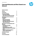
Use Case Study: Implementing a VMware ESXi Cluster with Dell Active System Manager Author: Amy Reed Dell Group: Software Systems Engineering Use Case Study: Using Active System For VMware Cluster Environment Configuration This document is for informational purposes only and may contain typographical errors and technical inaccuracies. The content is provided as is, without express or implied warranties of any kind. © 2012 Dell Inc. All rights reserved. Dell and its affiliates cannot be responsible for errors or omissions in typography or photography. Dell and the Dell logo are trademarks of Dell Inc. Microsoft is a registered trademark of Microsoft Corporation in the United States and/or other countries. Vmware, vSphere, and vMotion are trademarks of Vmware, Inc. Other trademarks and trade names may be used in this document to refer to either the entities claiming the marks and names or their products. Dell disclaims proprietary interest in the marks and names of others. December 2012| Rev 1.0 2 Use Case Study: Using Active System For VMware Cluster Environment Configuration Contents Introduction ........................................................................................................... 4 Active Infrastructure ................................................................................................. 4 Active System Manager (ASM) ...................................................................................... 4 Fabric A, iSCSI-Only Configuration (No Data Center Bridging) ................................................ 5 Fabric B, LAN-Only Configuration .................................................................................. 6 Network Partitioning (NPAR) ....................................................................................... 8 Pre-Requisites Introduction ......................................................................................... 8 Infrastructure Setup Using Active System ....................................................................... 10 Create Networks and Identity Pools ........................................................................... 11 Discover Chassis ................................................................................................... 12 Create Management Template ................................................................................. 12 Create Deployment Template .................................................................................. 13 Configure Chassis ................................................................................................. 16 Deploy Servers .................................................................................................... 17 Cluster Setup and Configuration .................................................................................. 18 Configure ESX Management Network .......................................................................... 18 Create Cluster ..................................................................................................... 19 Add Hosts to Cluster ............................................................................................. 19 Configure Management Network, Storage Network, vMotion Network, and Customer Networks .... 20 Using A Host Profile .............................................................................................. 24 Deploying Virtual Machines ..................................................................................... 25 Expanding Cluster Capacity ..................................................................................... 25 Glossary ............................................................................................................... 25 3 Use Case Study: Using Active System For VMware Cluster Environment Configuration Introduction This whitepaper describes how to use Active System Manager (ASM) Management and Deployment templates to configure a blade system infrastructure to host a VMware cluster. The servers in this cluster will be configured by Active System Manager to boot from an ESXi 5.1 image on their internal redundant SD cards which have been pre-installed with ESX 5.1 at the factory. Active System Manager will assist with enabling Converged Network Adapter (CNA) iSCSI connectivity and configuring I/O Module Network to support the iSCSI data volume connections to the required shared storage for the cluster. The network containing only the storage traffic is the iSCSI-only network. Active System will also assist with configuration of the CNA partitioning for the networking required for hypervisor management, vMotion, and the virtual machine networks. The network containing all other traffic aside from the storage traffic is the LAN-only network. This white paper introduces several Active System concepts for infrastructure management and walks through the real world use case of Active System iSCSI-Only and LAN-only infrastructure setup, blade environment setup with Active System Manager, and finally VMware host and cluster configuration. Active Infrastructure Dell’s Active Infrastructure is a family of converged infrastructure offerings that combine servers, storage, networking, and infrastructure management into an integrated system that provides general purpose virtual resource pools for applications and private clouds. These systems blend intuitive infrastructure management, an open architecture, flexible delivery models, and a unified support model to allow IT to rapidly respond to dynamic business needs, maximize efficiency, and strengthen IT service quality. In this use case Active Infrastructure is used to provide compute resources and required connectivity to both storage networks and standard Ethernet networks in order to support a VMware cluster. The infrastructure to support these connections is provided via two separate fabrics in the blade chassis, one containing only iSCSI traffic and one containing only standard Ethernet networking traffic. Fabric A in the blade chassis provides two independent Dell Force10 PowerEdge M I/O Aggregators (IOAs) for redundant connections to the storage distribution devices. Fabric B in the blade chassis provides two independent IOAs for redundant connections to the LAN distribution devices. The iSCSI Storage Area Network (SAN) will allow the VMware ESXi 5.1 hosts to connect to the two or more shared volumes on the EqualLogic storage array required to create a cluster. The LAN network will carry the standard Ethernet traffic to support various required networks such as the hypervisor management network, the vMotion network, and the VM Networks which will provide networking for the virtual machines running on the various hosts. Active System Manager (ASM) Active System Manager simplifies infrastructure configuration, collapses management tools, and drives automation and consistency. Through capabilities such as template-based provisioning, automated configuration, and infrastructure lifecycle management, Active System Manager enables IT to respond rapidly to business needs, maximize data center efficiency, and strengthen quality of IT service delivery. 4 Use Case Study: Using Active System For VMware Cluster Environment Configuration Fabric A, iSCSI-Only Configuration (No Data Center Bridging) For this use case, Fabric A will be set up by Active System Manager for an iSCSI-only configuration. An iSCSI-only network contains iSCSI traffic and no other traffic. In the absence of technology such as Data Center Bridging (DCB), which enable converging LAN and SAN (iSCSI) traffic on the same fabric, an iSCSI-only network configuration is required to ensure reliability for high-priority SAN traffic. All devices in the storage data path must be enabled for flow control and jumbo frames. It is also recommended (but not required) that DCB be disabled on all network devices from within Active System Manager, since the network will carry only one type of traffic. This will ensure that all devices— including CNAs, iSCSI initiators, I/O aggregators, Top-of-Rack (ToR) switches, and storage arrays—share the same DCB-disabled configuration. DCB is an all or none configuration, in other words if you choose to enable DCB, it must be enabled end-to-end from your storage to your CNA. The ASM template configuration and ToR switch configuration of DCB in this case will drive the configuration of your CNAs as they should operate in “willing” mode and obtain their DCB configuration from the upstream switch. EqualLogic storage also operates in “willing” mode and will obtain its DCB or non-DCB configuration from the ToR distribution switches to which it is connected. In this configuration, the jumbo frame MTU size is set on the switches to 12000 to accommodate the largest possible packet size allowed by the S4810 switches. Make sure to set the MTU size in your own environment based on the packet size your devices support. In this example, specific ESXi hosts being configured for the cluster will only support an MTU of 9000, as a result the overall MTU for these paths will adjust down to 9000. Active System Manager will only configure hardware within the Active Infrastructure blade chassis environment, thus the distribution layer and above must be configured manually or by other tools. Active System Manager does not manage storage devices, thus these will also need to be configured by the system administrator. In this example, two Dell Force10 S4810 switches are used for the distribution layer devices and two Dell EqualLogic PS6010X are used as the storage arrays. The S4810 switches are configured as a set of VLT peers, and the storage arrays are connected directly to the distribution layer device. These switches connect the downstream Dell Force10 PowerEdge M I/O aggregator switches in the chassis with the upstream EqualLogic storage arrays. In an iSCSI-only configuration, the distribution switches have only four types of ports: Out-of-band management VLT peer ports Downlinks to the I/O aggregator in the M1000e chassis Connections to the Dell EqualLogic iSCSI storage array The Virtual Link Trunking (VLT) peer link is configured using 40GbE QSFP ports of the S4810 distribution layer switches. VLT is a Dell Force10 technology that allows you to create a single link aggregated (LAG) port channel using ports from two different switch peers while providing load balancing and redundancy in case of a switch failure. This configuration also provides a loop-free environment without the use of a spanning-tree. The ports are identified in the same manner as two switches not connected via VLT (port numbers do not change like they would if stacked). You can keep one peer switch up while updating the firmware on the other peer. In contrast to stacking, these switches 5 Use Case Study: Using Active System For VMware Cluster Environment Configuration maintain their own identities and act as two independent switches that work together, so they must be configured and managed separately. Downlinks to the I/O aggregators must be configured as LACP-enabled LAGs. LACP must also be enabled on the storage distribution switches to allow auto-configuration of downstream I/O aggregators and to tag storage VLANs on the LAGs, since they will be used to configure VLANs on the downstream switch. Figure 1. iSCSI-Only Network Diagram Routed Core 3 5 7 9 11 13 15 17 19 21 2 4 6 8 10 12 14 16 18 20 22 LNK 23 s u Stat WR P 1 ACT St ack No . LNK M RPS Fan ACT R es e t STER SYS ETHE RNET 1 ETHERNET 0 Hub Mode 2Gb ER R AC T SERIA L P ORT 0 CONTROL MODULE PSU MA 24 X2 ETHERNET 1 ETHERNE T 0 FAN 23 RS-232 18 20 22 24 26 28 30 32 34 36 38 40 42 44 46 Q SF P+ 48 60 56 LNK E thernet A CT S FP + SER IAL PORT 0 Invalid Address ETHERNET 0 16 ID ACT ERR PWR ETHE RNET 1 14 ETHER NET 2 Hub Mode 2Gb X2 X2 ETHERN ET 2 12 STE SYS MA FAN S4810P PSU R ETH ER NET 1 ETHERNET 0 ERR 10 AC T 8 PW R 6 SERIAL P ORT 0 4 CONTROL MODU LE 2 CONTROL MODULE 52 0 22 PWR ETH ER NET 2 1 21 ID E THE RN ET 2 ACT ERR PWR S4810P C OM B OP OR T S Invalid Address SERIAL PORT 0 CONTROL MODULE X2 Uplinks from IOA To iSCSI Only Distribution VLT Peers (Orange) 24 1 RS-232 52 0 2 4 6 8 10 12 14 16 18 20 22 24 26 28 30 32 34 SFP+ LAG C MC 1 K V M B1 C1 C 2 3 6 Gb 9 4 5 44 46 48 Q SF P+ 60 56 LNK Ethernet ACT Equallogic Storage 2 A2 LAG 20 1 19 2 1 19 18 4 42 P o we r C o n n e c t M8 0 2 4 k - 2 1 Gb 6 B2 P o we r C o n n e c t M8 0 2 4 k - 20 40 3 5 8 2 38 C MC 2 2 4 7 1 A1 C MC 2 1 i KVM 1 Gb C MC Gb 36 18 3 17 4 3 17 C O NS O L E C O NS O L E Dell M1000e Blade Enclosure with two PowerEdge M I/O Aggregators VLT Peer set LAG connections are seen as originating from a single network device. This allows connections from switches with separate management planes to be aggregated into a resilient, LACP enabled link aggregation. Legend iSCSI (blues) OOB Mgmt Connection LACP Enabled LAG 40GbE VLT Domain Link Uplinks from IOA (oranges) Fabric B, LAN-Only Configuration For this use case, Fabric B will be set up by Active System Manager for a LAN-only configuration. A LANonly network contains all other Ethernet traffic (but not iSCSI storage traffic). In this example, the LAN distribution layer switches are a set of Dell Force10 S4810 switches that are configured as a stack. Stacking allows these switches to be managed as a single, logical switch. Active System Manager will only configure hardware within the Active Infrastructure blade chassis environment, thus the distribution layer and above must be configured manually or by other tools. These switches connect the downstream Dell Force10 PowerEdge M I/O aggregator switches in the chassis with the upstream routed network. 6 Use Case Study: Using Active System For VMware Cluster Environment Configuration In a LAN-only configuration, the LAN distribution switches have only four types of ports: Out-of-band management Stacking ports Downlinks to the I/O aggregator in the M1000e chassis Uplinks to the routed network Downlinks to the I/O aggregators must be configured as LACP-enabled LAGs. LACP must also be enabled on the LAN distribution switches to allow auto-configuration of downstream I/O aggregators and to tag network VLANs on the LAGs, since they will be used to configure VLANs on the downstream switch. This example shows multiple ports of the Force10 S4810 configured to connect to the I/O Aggregator. Each port channel is also configured with the appropriate VLANs to carry the environment’s Ethernet traffic. These ports drive auto-configuration of VLANs on the I/O aggregator LAGs. Figure 2. LAN-Only Network Diagram Routed Core 3 5 7 9 11 13 15 17 19 21 LNK 23 ACT 2 4 6 8 10 12 14 16 18 20 22 24 s atu St R W P 1 Stack No . LNK M RPS Fan ACT Re s e t C O MB O P O R T S 21 22 23 24 Out of Band Management 1 PSU FAN R S-232 52 0 MAST S4810P SYS ER Uplinks from IOA To LAN Only Distribution (teal) 2 4 6 8 10 12 14 16 18 20 22 24 26 28 30 32 34 36 38 40 42 44 46 48 24 26 28 30 32 34 36 38 40 42 44 46 48 Q SF P+ 60 56 LNK Ethe rne t ACT MAST SYS F AN S4810P PSU ER SFP+ 1 RS-232 52 0 2 4 6 8 10 12 14 16 18 20 22 SFP+ Q SF P+ 60 56 LNK Ethe rne t ACT LAG C MC 1 K V M B1 C 1 3 5 7 C2 C MC 2 2 4 1 A1 6 8 2 3 Gb 9 4 5 A2 2 1 19 18 4 Legend 20 1 19 LAG P o we r C o n n e c t M8 0 2 4 k - 2 2 6 B2 P o we r C o n n e c t M8 0 2 4 k - 20 1 Gb C MC 2 1 i KVM 1 Gb C MC Gb 18 3 17 4 3 17 C O N S OL E C ON S O L E LAN from Routed Core OOB Mgmt Connection LACP Enabled LAG 40GbE Stacking Connections Uplinks from IOA (teals) Dell M1000e Blade Enclosure with two PowerEdge M I/O Aggregators 7 Use Case Study: Using Active System For VMware Cluster Environment Configuration Network Partitioning (NPAR) Network or NIC partitioning (NPAR) divides a network adapter into multiple independent partitions. In the case of the Broadcom 57810 CNA, these partitions can each support concurrent network and storage functions, which appear as independent devices to the host operating system. With iSCSI offload enabled on the CNA, one partition can appear as a storage controller while another partition with network enabled appears as a standard Ethernet NIC. NPAR supports the TCP/IP networking protocol and the iSCSI and FCOE storage protocols. It is important to note that different CNAs support NPAR differently—for example, not all CNAs support all protocols on all partitions. Refer to the documentation for your device, in this use case a Broadcom 57810, to determine which protocols are available. Pre-Requisites Introduction Before you begin configuration of your environment with Active System Manager, you must ensure that the following items are in place: Top of Rack Switch Configuration Out of Band Management Connectivity and Chassis Management Controller Firmware ESX Images on Managed Server’s SD Card or Hard Disk VMware vCenter Server Deploy Active System Manager Create EqualLogic Storage Volumes EqualLogic Multipathing Extenstion Module Top of Rack Switch Configuration The configuration of the top of rack distribution switches provides the access to the various iSCSI and standard Ethernet networks, while the configuration of the top of rack switches drives the autoconfiguration of the Dell Force10 PowerEdge M I/O Aggregators (IOA). It is important to ensure that each IOA has exactly one uplink to the desired top of rack distribution switch and that this uplink is configured with LACP enabled as well as the VLANs needing to be accessed from that fabric. The uplink can be configured using combinations of ports on the IOA from a single 10 Gb connection and up to six 40 Gb connections. Despite the number of connections, only a single uplink can be configured on the IOA. M1000e Out of Band Management Connectivity and CMC Firmware The out of band management network is the primary network which the Active System Manager will use to configure the Chassis, I/O Modules, and Servers in the environment. A simple flat network with no VLANs is used for access to the management interfaces for these devices. In Active Infrastructure the Active System Manager will need to be deployed to an ESXi Host with access to this management network. 8 Use Case Study: Using Active System For VMware Cluster Environment Configuration The Chassis Management Controllers (CMCs) within the M1000e blade environment are the main access point to the management of the blade chassis, I/O Modules, and servers. It is a Dell best practice to configure and connect redundant CMC modules to the out of band management network. The ASM virtual appliance will also require access to the same network the CMC’s are plugged into. Active System Manager also requires that prior to discovery of a chassis, the CMC firmware must be at a minimum of version 4.0 or later. ESX Images on Managed Server’s SD Card or Hard Disk For the servers in this example, it is assumed that ESXi has been ordered from Dell and pre-installed on the SD card of each server. If ESXi is not already present on each host it is required that ESXi is installed on the SD card or hard disk of the server. While Active System Manager doesn’t execute OS or Hypervisor deployment, it can assist with configuration of the server to prepare it for either an iDRAC secure boot install or a PXE install. See the Active System Manager User Guide for more information. VMware vCenter Active System Manager will reside on an ESXi host within your environment. This host cannot be present in the blade chassis being managed. In order to deploy Active System Manager, you will also be required to have either VMware vSphere Client or Server. In this example, a cluster will be created with the managed hosts, thus it is required that VMware vCenter Server be present and accessible to the managed ESXi hosts in the environment. In order to deploy the Dell Equallogic Multipathing Extension Module to your hosts, you will also be required to install vSphere CLI on the server from which you are managing your virtualized hosts. Deploy Active System Manager Active System Manager is infrastructure management software, which simplifies infrastructure configuration, collapses management tools, and drives automation and consistency. Through capabilities such as template-based provisioning, automated configuration, and infrastructure lifecycle management, it’s a single point of control for key infrastructure. Active System Manager is packaged in an OVF format to enable easy deployment within a virtualized environment. An administrator deploys the Active System Manager OVF via vCenter onto a host with connectivity to the out of band management network for the Active Infrastructure blade environment. After the initial deployment, the product’s user interface is remotely accessible via a web browser. For more information on deploying Active System Manager see the Quick Installation Guide for the product. Create EqualLogic Storage Volumes The VMware cluster which will be created after using Active System Manager to configure the blade server and blade networking will require access to at least two shared storage volumes. In this use case the iSCSI storage will be a Dell EqualLogic PS6010X. It is necessary to create two large volumes and enable these volumes for access by multiple iSCSI initiators. This is required because there will be at least two connections for redundancy from each host which is added to the cluster. Active System Manager has the ability to assign IQN names for a server’s CNA. In this case we will be manually assigning IQN names in ESXi, but for ease of management and consistency between consoles, it is recommended to utilize the IQN names which are assigned by Active System Manager from its identity pool. Since Active System Manager identities have not yet been assigned, you will need to update the access control list for these volumes once the identities have been assigned from the Active System Manager pool after deployment of your template. Once you determine the iSCSI IQN names which you will assign to each of your 2 iSCSI adapters per host, you will add these IQN names to the access list for each of the shared volumes created. 9 Use Case Study: Using Active System For VMware Cluster Environment Configuration Keep in mind IQN names have a specified format and it is recommended to maintain this format to avoid issues when customizing your iSCSI initiators in ESXi. Keep a record of the IQN names assigned to each of the shared storage volumes as they will be required later when the iSCSI connections are configured on each of the ESXi hosts. Figure 3. IQN Naming Specification EqualLogic Multipathing Extension Module (MEM) VMware vSphere provides the Pluggable Storage Architecture (PSA), which enables you to configure multipathing for high availability and increased performance. The modular design of the architecture accepts third-party multipathing plugins that enable enhanced functionality specific to storage device models. When using EqualLogic storage with VMware, Dell recommends also utilizing the EqualLogic Multipathing Extension Module (MEM). MEM provides the following enhancements to the existing VMware multipathing functionality: Increased bandwidth Reduced network latency Automatic connection management Automatic load balancing across multiple active paths MEM and the full associated documentation can be obtained from the Dell EqualLogic support website at https://support.equallogic.com/secure/login.aspx. Additional configuration documentation may be obtained from Dell Tech Center at http://en.community.dell.com/techcenter/storage/w/wiki/3615.rapidequallogicconfiguration-portal-by-sis.aspx. MEM needs to be installed and configured on each host via the vSphere CLI after you have both ESX running on the host, and deployed the host via ASM. Each host will need to be placed in maintenance mode to install and configure MEM. Infrastructure Setup Using Active System Once you have completed the necessary pre-requisites and have deployed Active System Manager in your environment, you may proceed with using Active System Manager to configure the infrastructure required to deploy a VMware cluster. First, Active System Manager will be used to discover the chassis, update all of the device firmware to a baseline shipped with Active System Manager, and configure the fabric networking. In this example, three servers will be configured to boot from the ESXi image preinstalled on their SD cards. You will install MEM on each host and use it to configure your storage networking. Each host will be set up to provide two iSCSI connections, one on fabric A1 and one on fabric A2 which will be used for the shared data volumes required by the cluster. Each host will also be configured to split the ports on the fabric B1 and B2 CNAs into four partitions respectively. Each of these partitions will be used to support a different redundant network required by the host or VMs (for 10 Use Case Study: Using Active System For VMware Cluster Environment Configuration example for heartbeat or vMotion). Finally, Active System Manager will configure the I/O Module server facing ports to provide access to the necessary VLANs required by the ESXi host. Create Networks and Identity Pools In Active System Manager, first create the various network and identity pools required for the overall environment. In this use case there will be five VLANs (16, 20, 22, 23, and 28) which will be used as follows: Table 1. VLAN ID 16 20 22 23 28 VLAN Usage and Fabrics Purpose iSCSI Storage Virtual Machine Network vMotion Virtual Machine Network Hypervisor Management Fabric A1 and A2 B1 and B2 B1 and B2 B1 and B2 B1 and B2 Keep in mind, all of the above VLANs should have been configured on your top of rack distribution switches on the downlink LAG to the I/O modules in the chassis prior to connecting them. Navigate to the Networking menu within Active System Manager and select “Networks”. For each of the above VLANs a network will be created in Active System Manager. For each network you will provide a name, a description, the network type, and the VLAN ID. The example below shows a network type of Private LAN, which could be used for traffic such as vMotion. Additional information is required for creating certain type of networks in Active System Manager. For example, when “SAN (iSCSI)” is selected as the network type, an additional option is provided to create a range of static IP addresses. These addresses can then be used when configuring the CNA hardware settings for iSCSI boot, which requires an IP address to be configured in the firmware of the device. In this case only iSCSI data volumes will be used, not boot connections, so the storage initiator IP addresses will be configured in ESXi. NOTE: You must create a network in Active System Manager for every VLAN you wish to use in your environment. In addition to creating networks, Active System Manager has the concept of Identity Pools. These are the identities that will be assigned to the hardware CNA devices as necessary for MAC Addresses, iSCSI MAC and IQNs, and so on. To create an identity pool, you must first create a pool and give it a name. Once you have created a pool, you will then add identities to the pool. In the case of iSCSI this allows us to customize the IQN names which get assigned to the hardware adapters for iSCSI boot. In this case since iSCSI data connections will be used, identities will be assigned ESXi will be used to configure the IQN identities on the CNAs. It is recommended that you utilize the IQN pool capability of Active System Manager, record the IQN identities assigned by Active System Manager to the CNA, manually apply them to the ESXi host and include them in the access control list for your storage volume. This will allow you to maintain consistency between the identities shown in ASM, the storage management console, and vCenter. Active System Manager comes with a default “Global” pool for CNA MAC addresses for your environment. You may choose to utilize this pool for your network devices or create a new pool to assign new virtual MAC identities. 11 Use Case Study: Using Active System For VMware Cluster Environment Configuration Discover Chassis Once you have defined the networks and virtual identities for your environment you are ready to discover your blade chassis using Active System Manager. Chassis discovery will be initiated by providing the CMC IP Address of the chassis you wish to manage. It is critical that your Active System Manager virtual appliance and the chassis you wish to manage have network connectivity to one another via the out of band management network in order for the discovery process to be successful. You can discover your chassis either from the “Home” menu or from the “Devices” menu by selecting the “Discover Chassis” option. Then when prompted, provide the IP address of the chassis you wish to discover. You must also provide the chassis credentials to enable discovery of the chassis. The Dell Default credentials are automatically selected for you. If you have changed the credentials of the CMC you are trying to discover, you will need to create a new credential within Active System Manager containing the username and password required for access. Proceed to select the chassis you have identified for discovery and complete the wizard to start the discovery process, which will inventory the chassis, I/O Modules, servers, and networking devices in the chassis. Keep in mind that Active System Manager has a list of specific supported hardware, if you have unsupported hardware in the chassis Active System Manager will not inventory these devices. The discovery process may take several minutes to complete. Create Management Template Prior to configuring the chassis, an Active System Manager Management Template must be created which will specify the baseline configuration for the managed devices. To create a management template select “Create Management Template” option from either the “Home” or the “Templates” menu. Provide a name and description for your template. Specify the management networking you would like to use for your chassis, servers, and I/O Modules. You may choose to use existing IP addresses, assign an address via DHCP, or specify a static IP address from one of the management networks you have defined. Next, you must specify the credentials for your chassis, servers, and I/O Modules. You may choose to keep the credentials that you created for your chassis at discovery or create and assign new ones. You must also create credentials for the servers and I/O Modules. These credentials will be assigned to all devices once the management template is selected for configuration of a chassis. Optionally, you may also define any additional usernames and roles you would like to add to the management accounts for the CMC and the server iDRACs, as well as populate the monitoring, NTP, power, DNS, VLAN, and console access information you would like specified for your environment. NOTE: Use extreme caution when setting VLANs for your CMC or iDRAC devices. Setting these without the proper external environment configuration and routing could cause you to lose network connectivity to these devices. In addition, only CMC and iDRAC support VLAN tagging, the Dell PowerEdge M I/O Aggregator does not. As a result, using VLAN tagging for an Active System Management Infrastructure requires supporting both untagged and tagged VLANs on the out of band management switch connection to the CMCs as well as routing between these tagged and untagged VLANs in your environment. Now that management template creation is completed, the system is prepared to configure a chassis that has already been discovered. 12 Use Case Study: Using Active System For VMware Cluster Environment Configuration Create Deployment Template Before moving forward with configuration of the chassis, this section describes creating the Deployment Template for the ESXi hosts. This template will specify the various settings required to configure the BIOS, RAID, and Networking for the servers, as well as the server facing ports of the I/O Module. In this example, a Deployment Template will be created which will configure the servers to boot to the redundant SD module containing a factory-installed ESXi image. This will also configure fabric A and fabric B Broadcom CNAs to support iSCSI offload on fabric A for the ESXi data volume connections and the network partitioning on fabric B for the various standard Ethernet networking required by each host. To create a deployment template, select “Create Deployment Template” from either the “Home” or the “Templates” menu. Create a name and a description for your deployment template. Select the minimum CPU and memory capabilities for the host, which will allow servers that don’t meet your minimum requirements to be filtered from the available hardware. Specify the necessary BIOS settings for your ESXi host. In this example, it’s important to ensure that “Processor Virtualization Technology” is enabled and that the internal RAID is disabled since the server will be booting from the SD modules and using iSCSI storage. Next, the template for networking required on the servers must be configured. There is a fabric A and fabric B Broadcom 57810 2 port 10Gb CNA in each server. On fabric A both ports will be used to provide a redundant 10Gb connection to the iSCSI storage distribution device, thus this CNA will not be partitioned. On fabric B, both ports will be used to provide 4 redundant connections to the various networks outlined earlier in this document. Active System Manager presents the concept of Virtual NICs which are synonymous with partitions on a port of your networking devices. Each partition, or Virtual NIC, will be seen as an individual networking and/or storage adapter device in the operating system. For each partition, a dedicated portion of the available 10Gb bandwidth will be specified. You can also enable Bandwidth Oversubscription, or the ability to allow Virtual NICs to consume more than their guaranteed portion of the bandwidth in the event that it is available and not being used by other partitions. In this case, Bandwidth Oversubscription has been disabled. Active System Manager provides a wizard which will allow you to create each CNA partition. In this example, a Virtual NIC will be created for the iSCSI data volume connectivity. First, specify a name for the virtual NIC, or partition, on the CNA port. Then set the connection type to “SAN (iSCSI)”. Setting the network type will assist with configurations by filtering out networks that are not associated with SAN(iSCSI) to help ensure you are not assigning the wrong network to your template. In Active System Manager we have specified the Native VLAN in the Deployment Template as Storage16. Selecting the native VLAN in an ASM Deployment Template has the effect of configuring the server facing port of the I/O Module for untagged traffic. Specifying this Native VLAN in Active System Manager means that traffic ingressing from the server into this port must be untagged (in other words, it cannot be tagged by the CNA or by software in the OS). Once this traffic enters the I/O Module, the switch configuration will tag this traffic with the Native VLAN, in this case VLAN 16. This is important because the storage distribution device is expecting tagged traffic with VLAN 16. Using the native VLAN in the scenario of iSCSI data volume connections is optional; one could choose to tag in the operating system before making these connections. This method has been chosen simply to avoid that 13 Use Case Study: Using Active System For VMware Cluster Environment Configuration configuration in the OS. If this scenario was executing an iSCSI boot use case, specifying the Native VLAN would be a requirement. The bandwidth minimum and maximum in this case will both be set to 10Gb since this port will not be divided into partitions. Redundancy is enabled on this Virtual NIC. By enabling redundancy here, one iSCSI connection on fabric A1 and one on fabric A2 with identical settings will be enabled. A Virtual Identity Pool is specified from which to consume iSCSI IQN/MAC identities. Finally the networks that will be applied to this partition must be selected. These are the networks, or VLANs, that will be allowed to ingress the server facing port of the I/O Module. A similar process will be followed to create the Virtual NICs for the standard Ethernet connectivity. For the B fabric devices each port will be divided into four partitions, each carrying different VLANs. A new Virtual NIC will be created for the VMware management traffic. This will be used for communication between the vSphere console and the ESXi hypervisor hosts. The connection type is specified as LAN and a Native VLAN is not selected here. One Gb of the available 10Gb bandwidth is allocated for this port due to minimal throughput needs. Since redundancy has been selected, another partition identical to this configuration will also be configured on the second I/O Module in this fabric. The Global or default Virtual Identity pool is selected which will assign a Virtual MAC address from the pool to this partition. Finally, the network to associate with this virtual NIC is selected which will enable VLAN traffic on the server facing port of the I/O Module. This process is repeated three more times for each of the other Virtual NICs which need to be created on the host. Two Virtual NICs, or partitions, will be created for Virtual Machine networks on VLAN 20 and 23 and allocated 4 Gb each. Finally, one Virtual NIC will be created for vMotion traffic on VLAN 22 which will be used by the hosts in the cluster for vMotion. Once the Virtual NIC configuration has been completed, the deployment template will present a summary screen with the configuration choices. Here you can view the bandwidth specified for each NIC. In the case of the fabric A NICs the full 10Gb is allocated to a vNIC, or port, since in this case the CNA is not partitioned. In the case of fabric B used for the standard Ethernet traffic, the port has been divided into 4 partitions and the total bandwidth adds up to the 10Gb available on that port. It is important to note that you should never exceed the devices bandwidth limitations, as this could cause network issues. “PCI” was selected as the Virtual NIC Mapping order. The Virtual NIC Mapping Order determines how virtual NICs are mapped to the partitions on each port of an adapter. Selecting Physical Partition consecutively assigns virtual NICs to partitions (for example, Port1/Partition0, then Port1/Partition1, and so on). Selecting PCI Function assigns virtual NICs by alternating between ports (for example, Port1/Partition0, then Port2/Partition0, and so on). Different operating systems have different mapping order methods—for example, RHEL 6.2 and ESX 5.0 both use PCI function to enumerate partitions. Below is an example that shows four Active System Manager virtual NICs where “Redundancy” has not been selected in the deployment template. On the left side of this diagram you can see how the virtual NICs in Active System Manager map to the physical NIC partitions when you map based on PCI Function order. You should note that the four virtual NICs have been spread evenly across the partitions of both 14 Use Case Study: Using Active System For VMware Cluster Environment Configuration physical ports of the device. This allows you to distribute the load of these devices across both of your I/O Modules. On the right side of the diagram you can see how the virtual NICs in Active System Manager map to the physical NIC partitions when you map based on Physical Partition order. Your virtual NICs map in order to your physical NIC partitions, but you do not maximize the entire fabric of I/O Modules. Figure 4. Mapping Order Example without Redundancy Below is a different example that shows four Active System Manager virtual NICs where “Redundancy” has been selected in the deployment template. You’ll notice that in both cases the virtual NICs are even distributed across the partitions on both ports of the device, fully utilizing both fabrics. 15 Use Case Study: Using Active System For VMware Cluster Environment Configuration Figure 5. Mapping Order Example with Redundancy Going forward with Deployment Template configuration, you will set the “OS Boot” type to “SD Card”. This assumes you have ordered your server from Dell with ESXi pre-installed on your SD module. If this is not the case, you may configure your Deployment template to use a one-time boot mechanism such as PXE or iDRAC secure boot to install an ESXi image to the SD card. This configuration would have a slightly different Deployment Template configuration than what is described in this use case and is beyond the scope of this document. NOTE: PXE install requires a PXE server on the Native VLAN of the device you wish to PXE boot from. The Deployment Template was specified to include a boot sequence. In this case the Boot Mode was set to BIOS, and Boot Sequence Retry was disabled. Within the template you can view the current boot sequence, and adjust items as necessary. In this case the template has been set to boot from the Hard Disk first. It was also ensured that the Internal SD Card is listed as the first Hard Drive device. Once the boot sequence has been specified, verify the full contents of the Deployement Template in the summary, and save the template. Configure Chassis Now that both the management template and deployment templates are in place, the management template that was created in earlier steps will be used to configure the chassis. From either the “Home” or the “Devices->Chassis” menu, select the option to “Configure Chassis”. The wizard that appears will present you with the chassis that have been discovered by Active System Manager. Select the chassis you wish to configure and proceed with the wizard. 16 Use Case Study: Using Active System For VMware Cluster Environment Configuration Part of the chassis configuration process is to bring all of the firmware in the devices in the chassis to a baseline level. The wizard will display the firmware which will be updated on each device. You must select the option to update the firmware to proceed with configuration of the chassis. Active System Manager requires a certain minimum level of firmware to be installed on the device for management. The next step is to specify your fabric type. This identifies the purpose for which the I/O Module in your chassis will be used. In this example, fabric A will carry all of the iSCSI SAN traffic. There are two I/O Modules in fabric A and these will allow redundant connectivity to the iSCSI storage distribution devices. The Fabric Purpose is set to “SAN iSCSI” which will ensure storage best practices, such as jumbo frames, are used when configuring this fabric. Because there are separate iSCSI and LAN fabrics, DCB isn’t required to be enabled in this configuration and since DCB is required end-to-end if enabled, it will be disabled for this example. Finally, the storage networks which will be present on fabric A are selected. In this case the only storage network which will be used is the single storage network called “Storage16” which represents VLAN 16. Continuing on to configure fabric B in the chassis. Fabric B will carry only standard Ethernet traffic. There will be two redundant I/O modules which will connect to the LAN distribution devices at the top of rack. The purpose of this fabric is specified as LAN. DCB will be disabled as it was with fabric A since it will not be enabled end-to-end. Finally the networks are selected which will be present on this fabric. In this example VLAN 20 and 23 will be included for Virtual Machine networks, VLAN 22 for vMotion, and VLAN 28 for VMware Management. Fabric C is not populated in this chassis with I/O Modules, so fabric C connectivity will be left unspecified. Next, the management template which was created earlier in this process called “VMwareClusterEnvironment” is selected. The identity, DNS, and location information can be specified on the chassis, as well as the DNS information for servers and hostnames for the I/O Modules. Finally the configuration can be reviewed and completed. The chassis will take several minutes to apply the management template and to baseline the firmware and the settings. Once the chassis, servers, and I/O Modules have reached the “ready” state, they are ready for deployment. Deploy Servers Once the chassis, servers, and I/O Modules have been discovered and configured in preparation for use as members of the VMware cluster, the servers are ready for deployment. The four servers which will be the initial members of the cluster will be deployed using the previously created deployment template. You can save time deploying several servers which require identical configuration at once using Active System Manager Deployment Templates. You may begin the deployment process by selecting the “Deploy” option from either the “Home” or the “Deployments” menu. You will then be required to select the deployment template which you previously created and provide your deployment with a name and description. When deploying multiple servers with a single template, the actual deployment name will be an enumeration of the name you provide. Once you have identified your deployment, you will select which servers you would like to include in it from a list of servers matching the filtering criteria you specified in your deployment template. Filtering criteria will include things such as the number of CPUs, memory, networking available, and so 17 Use Case Study: Using Active System For VMware Cluster Environment Configuration on. Select one or more servers you wish to deploy to under the category of “Manual Server Selection”, then complete the wizard to start deployment. The deployment of servers should take several minutes to complete. You may check the status of your deployments by navigating to the “Deployments” item in the navigation menu on the left. Once your deployments enter the “Activated” state, your servers have completed the deployment process and are ready to be configured for inclusion in your cluster. Cluster Setup and Configuration Configure ESX Management Network Once you have deployed your servers, you will want to power them on from the “Deployments” menu. In order to create the cluster, one should ensure that a connection can be established to each host via vCenter Server. In order to do this the NIC which has been selected for VMware management traffic must have an IP address and be selected on the host as the management NIC. In this case this will be done by logging into the server via the iDRAC remote console, manually selecting the correct NIC, and providing it with a static IP address. There are methods to automate networking setup within your ESXi host, but that is beyond the scope of this document, you may refer to the VMware documentation for more information on this subject. The iDRAC on the host will be accessed via the iDRAC console. To do this in Active System Manager, go to the “Deployments” menu and click on the IP hyperlink in the “Server IP Address” column. This will launch the iDRAC GUI. Using the credentials configured via your Active System Manager template you will log into the iDRAC and launch the remote console. You should now be able to access and login to the ESXi hypervisor on the host. If you have not done so already, it is recommended to set the credentials for this host. Next you will navigate to the menu which will allow you to configure the management network of this host. First you will need to verify that the network adapter selected for management traffic is the same one you have identified and assigned via Active System Manager deployment template. You can find the Virtual MAC address assigned to the partition you have selected for VMware management traffic by viewing the “Network Identity” tab shown within the specific server deployment in Active System Manager. Once you have obtained this MAC address, you can select this NIC as the adapter to use for management traffic in ESXi. Next you will configure the appropriate VLAN on this adapter. Because the Deployment Template has been configured to expect tagged traffic from the VMware management partition, it must be ensured that the hypervisor is configured to tag the traffic on that partition. Navigate to the VLAN setting in the ESXi console UI and set the VLAN ID to 28, which is the VLAN which has been configured for this traffic by Active System Manager. Finally configure the IP information for the host. Set a static IP address, subnet mask, and gateway for the network. Once configuration of the management network information is completed, save the configuration, restart the management network, and run the network test to verify connectivity. Once the test has passed, the environment is ready to create a cluster in VMware vCenter Server. 18 Use Case Study: Using Active System For VMware Cluster Environment Configuration Create Cluster Before adding hosts to the vCenter environment, create a cluster for these hosts to reside in. Creating a cluster will provide the ability to pool the resources of all of the added hosts. Two or more iSCSI volumes will be utilized for the clusters datastores which will be used to store the virtual machines hosted by the cluster. The cluster will be created and configured to provide HA, DRS, and fail-over capabilities so that if one of the hosts is lost, the virtual machines on that host may be migrated to other healthy ESXi hosts within the cluster. To create a cluster, go into your vCenter Server instance, right click on the datacenter you wish to place the cluster in, and select “New Cluster”. vCenter Server will walk you through a wizard to create your cluster. In this example both HA and DRS have been enabled for the cluster. This will provide the ability to detect failures and provide rapid recovery for any deployed virtual machines. DRS will give us the ability to manage hosts as an aggregate pool of resources and will allow vCenter Server to manage the assignment of virtual machines to hosts automatically to balance the load and enforce any resource allocation policies that are created. The cluster will be configured to be fully automated to attain the best use of resources. In this example power management for the cluster was not enabled, but these settings can be adjusted as needed for your specific cluster needs. Continuing through the New Cluster Wizard, ensure that host monitoring is enabled. Keep the default settings for Admission Control and Enable the setting which determines the amount of cluster capacity that is reserved for VM failover. In this cluster the Admission Control Policy setting was configured to tolerate 2 host failures. This number can be adjusted depending on the number of hosts in your environment and the specific needs of your cluster. The default settings were selected for the Cluster VM restart policy and Host Isolation response. For VM Monitoring only monitoring VMs was selected and the monitoring sensitivity was set to “High”. EVC was disabled for this cluster. These settings again are chosen for example purposes and may be modified to meet the specific needs of the cluster you require. For more information on VMware Cluster creation refer to the VMware documentation and best practices for clusters. Once vCenter Server has finished completion of you cluster creation you are ready to add hosts to the cluster. Add Hosts to Cluster Once you have successfully configured the management access settings (password and IP information) for your hosts and created your cluster in vCenter Server, you are ready to add your hosts to the VMware cluster. You will need the management IP Addresses and credentials for all the ESXi hosts you wish to add to your cluster. To add a host, right click on the cluster you just created and select “Add Host”. Enter the credentials and IP Address information for the host you wish to add. Enter any licensing information required for the ESXi host. Choose whether you will enable lockdown mode for your ESXi hosts, which will prevent remote users from logging into the host. Determine host to manage the resource pools for the host, and complete the wizard to add the host. This process should be repeated for each host you configured via Active System Manager. Once you have added all hosts to the cluster they are available for configuration of the remaining networking and storage needed to support the virtual machines which will be placed in the cluster. 19 Use Case Study: Using Active System For VMware Cluster Environment Configuration Configure Management Network, Storage Network, vMotion Network, and Customer Networks ESXi Networking Overview There are several networks that must be set up on the ESXi host. This section describes completing configuration of the hypervisor management network, vMotion, and Virtual Machine networks as well as adding networking for storage which is handled via the EqualLogic MEM. Reviewing what was configured on the servers through Active System Manager the figure below shows the networking topology on each of the servers. The first two ports on the CNA have been configured as single 10Gb partitions to the redundant storage fabrics in the chassis. This storage traffic is carried on VLAN 16. It is important to remember that the Active System Manager template was configured to allow VLAN 16 to be the Native VLAN for the server facing port on the blade I/O Module. This means that this port expects traffic from the server to be untagged, and will tag any ingress traffic from the server with VLAN 16, which is the storage VLAN. A vSphere switch will be configured on the ESXi host by EqualLogic MEM to handle this storage traffic and associate it with the storage adapter in ESXi to connect to iSCSI volumes. Since the I/O Module is expecting untagged traffic on this port a VLAN ID will not be configured on the iSCSI vSwitch. Figure 6. Example Port Configuration For ESXi Host Notice that each of the fabric B mezzanine cards on the server has been divided into four partitions, or Virtual NICs, as was specified in the Active System Manager Template. Port 1 and Port 2 on the mezzanine card connecting to fabric B1 and B2 in the chassis has been configured identically to provide redundant access to the LAN networks. The server facing port on the I/O module has been configured to carry four VLANs to the server CNA. Several vSphere switches will be configured on the ESXi host to associate with these virtual NICs. These will carry the hypervisor management, vMotion, and the virtual machine networks. VLAN 20 and VLAN 23 will be used as the virtual machine networks which will provide access to the networking assigned to deployed VMs. VLAN 20 will be specified as the native VLAN. This means virtual machines which access VLAN 20 will be allowed to utilize this VLAN without configuring VLAN tagging in the operating system. Any ingress traffic to the I/O module on VLAN 20 will be expected to be untagged coming from the server and will be tagged with VLAN 20 in the I/O Module. VLAN 23 will require the user to configure VLAN tagging in the operating system of the virtual machine. VLAN 22 will be used for vMotion traffic. Traffic on this VLAN will also be required to be tagged and configured on the vSwitch which will be set up for vMotion traffic on the host. 20 Use Case Study: Using Active System For VMware Cluster Environment Configuration Configure Redundant Hypervisor Management Network Upon initial setup of the host, vmnic2 was selected as the management NIC, this corresponds to the B1 fabric mezzanine card port 1 partition 1 of the CNA. Another NIC (vmnic3) will be added for redundancy and will corresponds to port 2 partition 1 of the B2 fabric mezzanine card. Both of these virtual NICs will be configured for VLAN 28 which was already configured on the vSphere switch carrying the management traffic. Here another NIC will be added to the vSwitch. In the vSphere Client, access the host networking under the “Configuration” tab, vSwitch0 has already been configured for the management network. Select the “Properties” link near the vSwitch and switch to the “Network Adapters” tab. Click the “Add” button to add the second NIC. In this case vmnic3 corresponds to the redundant partition which will carry the hypervisor management traffic. This NIC is selected in the “Add Adapter Wizard”. Continuing with the wizard, configure the failover order such that vmnic3 is specified as a “standby adapter”. Then finish the configuration wizard. There are now two adapters configured for management traffic, one active and one standby for vSwitch0. Configure iSCSI Network and Storage Adapters When Using EqualLogic Storage To view the iSCSI hardware adapters available on your host in the vCenter management console, go to the “Configuration” tab for that host and select the link to “Storage Adapters”. As mentioned previously, during server Deployment, Active System Manager assigned storage IQNs to the Broadcom 57810 adapters which we designated as iSCSI connections. Because Active System Manager cannot modify the configuration of the ESXi host software, we need to manually configure the IQN names of the storage adapters in ESXi to match what Active System Manager has designated. Review your Active System Manager deployment details to obtain the IQNs of each of the two iSCSI adapters. Based on your Active System Manager deployment configuration you should see two Broadcom iSCSI adapters listed on the configuration pages in vCenter, because they were enabled for iSCSI. To change the IQN name, right click on the first Broadcom iSCSI adapter and select properties. Under the “General” tab click the “Configure” button to configure the iSCSI IQN and/or alias for this adapter. Since an iSCSI IQN was from the Active System Manager pool, it is recommended to enter the IQN assigned by Active System Manager for consistency, but if you wish to use a different IQN you may. Note that VMware software does check for the correct IQN format and will not let you enter a value if it doesn’t follow the IQN naming specification referenced earlier in this document. Repeat this process for the second adapter. In order to make connections to the iSCSI networking, the Broadcom 57810 adapter support in ESXi requires that a vSphere switch and vmkernel are created to associate with the Broadcom CNA for iSCSI traffic. As previously mentioned ports 1 and ports 2 of the Broadcom CNA have been configured for iSCSI traffic at the hardware level, these correspond to vmnic0 and vmnic1 on the ESXi host. When using Equallogic storage, this configuration will be handled for you via the EqualLogic MEM. To obtain the MEM software and the latest detailed instructions on using the Dell EqualLogic MEM see the EqualLogic support pages at https://support.equallogic.com/secure/login.aspx. For this example, the vSphere CLI was used to install the Dell EqualLogic MEM on each host. First the ESXi host was placed in maintenance mode. Then the EqualLogic MEM was downloaded and made available on the vSphere management server. From the vCLI command prompt, change to the directory where the MEM was stored and type the following command: setup.pl --install --server=<ESXi host IP address> --bundle=<bundle file name> 21 Use Case Study: Using Active System For VMware Cluster Environment Configuration Where <bundle file name> is the zip file, such as dell-eql-mem-esx5-1.1.2.292203.zip. When prompted, login as “root” with the correct ESXi host setup password. This process could take several minutes. Successful setup will present the “Clean install was successful” message. Next configure the host using the MEM. At the same vCLI prompt, execute the following command. Note that some of the parameters below are optional, so refer to the MEM documentation to determine the specific needs for your environment. setup.pl –-configure –-server=<ESXi host IP address> --vswitch=vSwitchISCSI – -mtu=9000 –-nics=vmnic0,vmnic1 --ips=172.16.53.38,172.16.53.39 -heartbeat=172.16.53.40 --netmask=255.255.0.0 --vmkernel=iSCSI – groupip=172.16.0.20 You will be prompted for the host username and password. Once configuration has completed, the iSCSI networking and storage HBAs should be configured on the host. At the end of configuration the storage HBAs are scanned for new volumes. You can view the discovered volumes from the “Configuration > Storage Adapters” menu. Select the configured iSCSI HBAs and confirm that the shared volumes were discovered. If the shared volumes were not discovered, verify the access credentials and rescan the adapters. Configure iSCSI Network When Using Other (Non-EqualLogic) iSCSI Storage If you are using EqualLogic storage and MEM, you can skip this section. If you are not using EqualLogic storage, then you will be required to manually set up your storage networking on the ESXi host. A vSphere switch must be created and associated with each of your two storage adapters. On the host “Configuration” tab go to the “Networking” section. Select the link to “Add Networking”. The iSCSI Network requires the connection type to be vmkernel. Select the two adapters which have been configured for iSCSI by Active System Manager, in this case vmnic0 and vmnic1. Provide a label for your network, for convenience this network will be called “iSCSI” and there will not be a VLAN ID set for this network. Even though the VLAN for storage is 16, because the I/O Module port has been configured for VLAN 16 as the Native VLAN, the host should be configured not to tag traffic. Select the option to use the port for management traffic. Next, provide the IP information for this network. Be sure to select a valid IP address on the storage network. In this case the addresses have the first two octets set for 172.16.x.x and use a subnet of 255.255.0.0 or /16 (class B network). Continue through the wizard and complete the configuration. Next there are a few configuration settings which need to change on the iSCSI network. Select the “Properties” option for the iSCSI vSwitch that was just created. On the general tab, change the MTU setting to 9000. For the storage network the MTU was configured to be as large as possible to support storage traffic. The MTU on the I/O Module and the top of rack distribution switch was set to 12000 in this environment, but ESXi will not let you configure an MTU higher than 9000 so this path will operate with an MTU of 9000. Next go to the NIC Teaming tab. For iSCSI, you may only use one active adapter at a time for the vmkernel you will associate with your adapter, so one of the adapters must be configured as“unused”. Configure Storage Adapters When Using Other (Non-EqualLogic) iSCSI Storage If you are using EqualLogic storage and MEM, you can skip this section. To view the iSCSI hardware adapters available on your host go to the “Configuration” tab for that host and select the link to “Storage Adapters”. Based on your Active System Manager deployment template you should see two Broadcom iSCSI adapters listed. Right click on the first Broadcom iSCSI adapter and select properties. Under the “General” tab, click the “Configure” button to configure the iSCSI IQN and/or alias for this 22 Use Case Study: Using Active System For VMware Cluster Environment Configuration adapter. Since an iSCSI IQN was from the Active System Manager pool, it is recommended to enter the IQN assigned by Active System Manager for consistency, but you may use a different IQN if you wish. Note that VMware software does check for the correct IQN format and will not let you enter a value if it doesn’t follow the IQN naming specification referenced earlier in this document. Next go to the “Network Configuration” tab and click “Add” to bind the appropriate vmkernel Network Adapter with this storage adapter. For the first storage adapter select vmnic0 which in this case is associated with vmk1. You will be able to confirm you have correctly configured your iSCSI vSwitches and adapters because VMware should report that your configuration is “Compliant”. Finally, add the target information for the two shared iSCSI storage volumes which will be used for this cluster. This will require you to have the IP information, port, and iSCSI target names for the two shared volumes to which a connection will be made. Once this information has been added and saved vCenter will prompt for a rescan of the host adapter, which should cause the previously created storage volumes to be discovered. These volumes will then be visible under the “Details” section for the adapter you just scanned. Repeat the process to connect the second, redundant iSCSI storage adapter to these same two volumes with the following difference: the second storage adapter should be associated with the second VMKernel (vmk) Network Adapter, which in this case is vmnic1. Once both adapters have been connected and rescanned each should have exactly one connection to the same two storage volumes. Once all four connections are active, the shared storage can be added, formatted, and set up for multipathing. This process should be repeated on every host present in the cluster. Add Shared Storage In order for the cluster to function correctly it requires at least two shared storage volumes connected to all hosts in the cluster. In the previous steps it was ensured that both storage volumes were accessible by both storage adapters on all hosts in the cluster. The next step is to make the storage available for use by adding it and formatting it. The ESXi hosts will also need to take advantage of the redundant paths which have been set up to this storage by using connections on both fabric A1 and A2 which were configured using Active System Manager. On the “Configuration” tab navigate to the “Storage” link, then select the link to “Add Storage”. This will launch as wizard to add your storage volumes for access by this host. Select the storage type to be “Disk/LUN”. Select one of the two iSCSI volumes connected to in the last step. Select the file system version you would like to use. Enter a name for your datastore. Specify how much capacity of the datastore to make available for formatting, then complete the wizard. Repeat this process for the second shared volume. Enable MPIO When Using Other (Non-EqualLogic) Storage If you are using EqualLogic storage and MEM, you can skip this section. Once you have added and formatted your storage, you want to make sure to set the appropriate multi-pathing settings for these devices. There are currently two connections to each shared storage volume which will be used by the host. One path is on A1 using port 1 on the Broadcom CNA, and the second path is on fabric A2 using port 2 of the Broadcom CNA. To view both of these paths, highlight the storage volume on the “Configuration” tab in vCenter Server under the “Storage” link. Once the storage volume is 23 Use Case Study: Using Active System For VMware Cluster Environment Configuration highlighted, click the link to go to “Properties”. Click the “Manage Paths” button to go to the multipathing settings for this shared volume. By default the volume will be set to a “Fixed” multi-pathing configuration. For the purposes of this example, change this to a “Round Robin” configuration. This will allow both paths to the storage to be active and fully utilize the throughput of both ports. In addition, if one of the paths to the storage goes down, there is still a second path available so connectivity to storage will not be lost. Once Round Robin has been selected, click the button to “Change” the configuration. Once the change is complete, you should see both paths to the storage volume shown in the “Active” state. The necessary settings should be changed for the second volume on the host. Configure Remaining vMotion and Virtual Machine Networks Similar to the steps followed to create a vSphere switch for the iSCSI network, three additional vSphere switches will be created for the vMotion and Virtual Machine Networks. As noted earlier the vMotion network will be VLAN 22 and the Virtual Machine Networks will be VLAN 20 and 23. For the vMotion switch, ensure that when it is created, the connection type is selected to be “vmkernel”. Select the appropriate adapters (such as vmnicX) in ESXi that align with the Virtual NICs which were created in Active System Manager. Each of the three VSphere switches will be assigned two adapters aligning with the redundant adapters created in Active System Manager. For the vMotion switch this example uses the name “vMotion” and assigns VLAN 22 to the switch that aligns with the Virtual NICs created in Active System Manager. Select the options to enable this port group for both vMotion traffic and fault tolerance logging. Next, provide an IP address for this switch. In this case an IP address was selected which was accessible from the Hypervisor Management VLAN. The IP used used in this example had the first two octets of 172.22.x.x and the netmask of 255.255.0.0. Complete the wizard to finish creating the switch. Finally create two vSphere switches for the virtual machine traffic. The first vSphere switch will be for VLAN 20 and the second for VLAN 23. The exact same process will be followed for creating this vSphere switch, except that a Virtual Machine Network will be selected as the connection type. VLAN 20 was configured as the Native VLAN in Active System Manager, which means it is expected to have untagged traffic from the host, therefore a VLAN ID is not configured on this vSphere switch. Since VLAN 23 is not a native VLAN, you must configure its ID (VLAN ID 23) in the vSphere switch. At this point the host should have 5 vSphere switches configured for the various purposes outlined here. Using A Host Profile When using a VMware Cluster, all hosts should be configured in an identical manner. This means all networking, processor, storage, and so on should be the same. This can be a challenge to correctly implement manually. VMware provides the Host Profile tool to make this configuration easier. Once you have set up a single host with networking, storage, and any other configuration, you can use this host to create a Host Profile. This Host Profile can then be used to configure any additional host which you bring into the cluster To create a host profile, right click on the host from which you wish to capture the configuration. Then select the menu item “Host Profile -> Create Profile From Host” to capture the settings. Finally, provide a name and a description for the profile. 24 Use Case Study: Using Active System For VMware Cluster Environment Configuration Once the settings are capture in the Host Profile, this profile can be applied to the other hosts in the cluster. Keep in mind that some settings are still host-specific and you will be prompted to configure these settings when you deploy the host profile to the host. For example, you will have to create specific MAC Addresses, IQNs, and IP Addresses when you apply your host profile. Once you apply the host profile to all of the servers in your cluster and they are all in compliance with the profile, you are prepared to deploy virtual machines. Deploying Virtual Machines Once your cluster is created, your hosts have been added and configured, and your shared storage is available to all hosts, you are ready to deploy virtual machines. In this case, an OVF file will be used. This is a virtual machine image which has been previously created. To deploy your virtual machines, you may choose to create the virtual machines and then deploy your operating system directly to the virtual machines. In this example, multiple OVF files will be deployed to the cluster. Active System Manager and vCenter Server have both been configured to access VLANs 20 and 23 which will be the LAN access to the network. The virtual machines will require access to both of these networks. To do this, add two vNIC to each virtual machine. When configuring these adapters specify the VLAN or vSphere switch which was created in the earlier section to enable the network connection for that adapter. Expanding Cluster Capacity After your initial cluster deployment, you may find that you want to add additional capacity to your cluster. Active System Manager can help make this process easy by simply plugging additional servers into your chassis, discovering these servers, and applying the necessary templates. Making use of Active System Manager for this purpose makes adding capacity to your cluster quick and easy and ensures that you add compatible, identically configured servers to your resource pool. Glossary Date Center Bridging (DCB) - DCB standards are enhancements to IEEE 802.1 bridge specifications to support multiple protocols and applications in the data center. They support converged infrastructure implementations to carry applications and protocols on a single physical infrastructure. IEEE DCB task group: http://www.ieee802.org/1/pages/dcbridges.html Link Aggregation (LAG) - used to bundle multiple individual physical network connections so that a single logical link is created. This is typically used for combine two or more Ethernet links together to provide increased throughput and a form of load balancing for when an individual link may get saturated. Link Aggregation Control Protocol (LACP) - provides a method to control the bundling of several physical ports together to form a single logical channel. LACP allows a network device to negotiate an automatic bundling of links by sending LACP packets to the peer (directly connected device that also implements LACP). Maximum Transmission Unit (MTU) – the largest size packet or frame that can be sent in a network 25 Use Case Study: Using Active System For VMware Cluster Environment Configuration Native VLAN – is an ASM Deployment Template term. When a Native VLAN is selected in an ASM Deployment Template, that VLAN ID is designated as an untagged VLAN on the server facing port of the blade I/O module. Virtual Link Trunking (VLT) – Force 10 technology that allows you to create a single link aggregated port channel using ports from two different switch peers providing redundancy in the case of a switch failure. These switches maintain their own identities and configurations and must be managed separately. 26