1
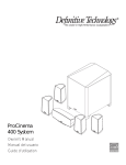
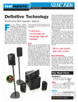
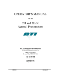
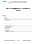
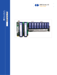
™
UIW RSS II
Reference Series In-Wall/In-Ceiling Surround Speaker
Owner’s Manual
Congratulations
Congratulations on your purchase of the Definitive Technology
UIW RSS II Loudspeaker. This reference quality loudspeaker
provides the highest level of sonic performance and construction
quality and is designed for easy flush-mount installation in
ceilings or walls of homes and commercial spaces. Six years of
intensive research and development by Definitive engineers,
working in collaboration with one of the world’s leading industrial
design firms, has produced the finest architectural loudspeakers on
the market. The beautiful upscale designer styling of this model
is perfect for the finest homes belonging to the most
discriminating homeowners.
The UIW RSS II Loudspeaker
The RSS II:
• Incorporates high-power, high-definition cast-basket Definitive
bass/midrange drivers combined with pressure-coupled lowfrequency radiators and state-of-the-art Definitive 1" dome tweeters.
• Incorporates polypropylene cones with butyl rubber surrounds.
• Incorporates a complete precision crossover system designed by
Definitive engineers for seamless driver blending.
• Incorporates a completely sealed non-resonant medite enclosure to
assure you of laboratory reference quality performance in your home.
• Is moisture resistant to allow use in bathrooms, etc.
• Is easily paintable and comes complete with mounting templates
and plastic paint masks.
• Can be used as an exceptional rear/side surround or main speaker
in a state-of-the-art home theater system or as stereo pairs in a
2-channel music system.
The Sound Quality Is Extraordinary
The UIW RSS IIs have been voiced by Definitive engineers (using the
superb facilities of the Definitive Technology Advanced Research Facility) to
the same high-end standards as all Definitive loudspeakers. The drivers and
baffles are perfectly integrated into the design to minimize the diffraction
problems that are inherent with most other in-wall loudspeakers. To ensure
that you experience the finest performance possible from your UIW RSS IIs,
we encourage you to read this owner’s manual to familiarize yourself with
the proper installation and set-up procedures.
Unpacking Your UIW RSS II Loudspeakers
Please Inspect For Shipping Damage
Each loudspeaker leaves our plant in perfect condition. Any visible or
concealed damage most likely will have occurred in handling after it left the
plant and should be reported at once to your Definitive dealer or the delivery
company that delivered your loudspeakers. Please unpack your system
carefully. Save all cartons and packing materials in case you move or need
to ship your system. Record the serial numbers found on the carton of the
UIW RSS II Loudspeakers in the appropriate place on your warranty card.
2
UIW RSS II Applications
The UIW RSS II is designed to be mounted in ceilings or in walls as a rear or
side surround speaker in stealth home theater systems of the highest quality.
In addition, they can be used as a front left, right or center main speaker in a
home theater or as a left or right stereo speaker.
UIW RSS II Positioning
Definitive’s UIW RSS II Loudspeakers are designed to be mounted in walls
or ceilings with excellent results. Because of their wide dispersion characteristics and other aspects of their superb sonic performance, mounting position
in your room is very flexible. Due to the different requirements of the wide
variety of room shapes and sizes, we recommend that you consult with the
custom installation specialist at your Definitive Technology dealer regarding
your own particular needs.
As a general guide when using the RSS II as a surround speaker:
• Try not to locate the RSS IIs forward of the main listening position.
• If ceiling-mounting these speakers directly on either side of the main
listening position, the speakers should be oriented so that one set of drivers
shoots at the listening position and the other set shoots away from the
listening position.
• If ceiling-mounting the speakers directly behind the main listening position, orient the speakers so that one set of drivers shoots towards the listening position and the other set shoots back away from the listening position.
Your Complete Definitive Home Theater
For best results, we recommend that you use Definitive speakers in
combination with your RSS IIs for the best overall sonic performance.
Painting Your UIW RSS II Loudspeakers
The UIW RSS II Loudspeakers are easily paintable and are shipped with
plastic paint masks (which should be retained even if you initially decide not
to paint the speakers). The grille and frame must be painted separately, and
for best results, prior to installation.
For the grille, spray painting is the recommended method. Follow the paint
manufacturer’s directions for ventilation and correct spraying procedure. Be
very careful not to clog the speaker grille with too heavy a coat of paint as
this will impair system sonic performance.
3
For the frame, spray painting is preferred but brush or roller will also give
good results. The supplied frame masks should be put in place to protect the
speaker components for whichever method you choose.
Installation Procedure Overview
The RSS II is designed to be installed inside the wall or ceiling of your home
quickly and easily. Because of its superb sonic performance, installation
location within your room is very flexible. Your room is not like anyone
else’s room, and because of its unique size and shape will have its own
requirements for optimal sonic performance. We recommend that you
consult with the Custom Installation Specialist at your Definitive Technology
dealer regarding your special needs or if you are at all uncertain about the
best and safest way to install your RSS II.
• Installation of this product must follow all local and state building code
requirements. We strongly recommend using a qualified, professional
installer who is knowledgeable of local building codes.
• The UIW RSS II is designed for both In-Wall and In-Ceiling mounting.
• For In-Ceiling mounting, you will need to shim (or frame in the enclosure)
with appropriate framing material.
• Before starting construction or modification of your ceiling, you should
familiarize yourself with any applicable local fire and building codes
• Make sure the locations you select do not conceal studs, electrical wiring or
plumbing. Prior to installation, hold the speaker in your chosen location to
make sure it meets the clearance requirements around obstacles such as
studs, corners, beams, lighting fixtures and door/window frames
• For In-Wall mounting, the speaker requires 11/4" of clearance inside the
wall, on all four sides of the cutout, to clear the lock arms. If the desired
location is closer than 11/4" to a stud on one of the long sides of the speaker,
the long side of the speaker enclosure must be installed directly against the
stud to prevent rattling.
• For In-Ceiling mounting, the speaker enclosure must be directly against
two joists and/or framing material on the two long sides that are to be
fastened with the screws. 11/4" of clearance is required on the two
remaining sides of the enclosure to clear the lock arms.
• For all mounting applications, 1" of clearance is required around the
cutout, on the outside mounting surface, to clear the speaker bezel.
4
• Also note that the installation of the RSS II may require some modification
of the joist structure in your ceiling. This should only be done by a competent professional who will configure the studs to maintain their structural
integrity and make sure that everything is in compliance with all local and
state building code requirements.
Installation Procedure Overview
(continued)
• Speaker wire must be run inside your ceiling as part of the installation
process of in-wall loudspeakers. Plan the connection before you start your
loudspeaker installation.
Step-by-Step Installation
Mounting options overview
• Installation of this product must follow all local and state building codes.
We strongly recommend using a qualified, professional installer who is
knowledgeable of local building codes.
• The UIW RSS II is designed to be mounted vertically In-Wall, and either
in-line with or at 90° to joists In-Ceiling.
• For In-Ceiling mounting, you will need to shim (or frame in the enclosure)
with appropriate framing material along one or both of the long sides of
the speaker.
Required cutout and cavity size for In-Wall Installation
• Template cutout size: 115/8"W x 97/8"L.
• Minimum size of cavity required inside wall is as follows:
– Depth: 37/8"
– Height: 137/8"
– Width: 121/8" See Diagram 1, page 10 for reference.
– Width: 11" (where desired location is closer than 11/4" to a stud on one
side) See Diagram 2, page 10 for reference.
– Width: 97/8" (where desired location is closer than 11/4" to a stud on two
sides) See Diagram 3 & 4, page 11 for reference.
Required cutout and cavity size for
In-Ceiling Installation
• Minimum size of cavity required inside wall is as follows:
– Depth: 37/8"
– Width: 97/8" between joists/framing material on sides with wood screws.
– Height: 137/8" between obstructions at ends where lock arms are to be
used (top & bottom ends) (11/4" of space required on each end of the
speaker to clear lock arms).
5
Step-by-Step Installation
(continued)
Hole location options and requirements
• In-Wall installation for studs spaced 16" on-center (or more):
– Place template at least 11/4" away from existing studs (to clear lock arms).
Template does not need to be centered between studs.
– Trace around template with pencil.
– Cut hole.
See Diagram 1, page 10 for reference.
• In-Wall installation for studs spaced 16" on-center (or more) where desired
location is closer than 11/4" to stud:
– Place template against inside of existing stud.
– Trace around template with pencil.
– Cut hole.
See Diagram 2, page 10 for reference.
• In-Ceiling installation, in-line with joists spaced 16" on-center (or more):
– Place template against inside edge of existing joist.
– Trace around template with pencil.
– Cut hole.
– If required, install supporting cross braces inside cavity.
– Install framing material inside cavity, running parallel to existing joists,
leaving 97/8" between frame sides.
See Diagram 3, page 11 for reference.
• In-Ceiling installation, centered, in-line with joists spaced 16" on-center
(or more):
– Center template between inside edges of existing joists.
– Trace around template with pencil.
– Cut hole.
– If required install supporting cross braces inside cavity.
– Install framing material inside cavity, running parallel to existing joists,
leaving 97/8" between frame sides.
See Diagram 4, page 10 for reference.
6
• In-Ceiling installation, 90 degrees to joists spaced 16" on-center (or more)
– Place template at least 11/4" away from existing joists (to clear lock arms).
– Template dose not need to be centered between joists.
– Trace around template with pencil.
– Cut hole.
– Install framing material inside cavity, running 90° to existing joists,
leaving 97/8" between frame sides.
See Diagram 5, page 12 for reference.
Gasket requirements and application
• There are two sizes of gasket strips included in the accessory pack with the
owner’s manual.
– 5 short gaskets.
– 2 long gaskets.
• For ALL installations where cavity depth is 4" or less, the gaskets are
to be applied as follows:
– 3 SHORT gaskets are to be applied across the back of the wooden
enclosure.
• For In-Ceiling and In-Wall installations where the side of the enclosure
ends against a joist, stud or installed framing material:
– One SHORT gasket is to be applied to each side of the enclosure that will
be against the framing material. The SHORT gasket is designed
to fit behind the bezel, between the lock arm openings.
– One LONG gasket is to be applied to each side of the enclosure that
will be against the framing material.
Connecting the speaker
• Run color-coded wires between the speaker cavity and amplifier
unit. When running the wires inside the ceiling to the opening, leave a
minimum of 18" of additional length in the cavity to facilitate speaker
connection.
• Fish wiring out of hole.
• Connect the speaker wires to the UIW RSS II taking care to make red to
red (+) and black to black (-) terminal connections.
• Refer to your amplifier or receiver loudspeaker wiring instructions, turn
off the unit and connect the speaker wires to the appropriate colored output terminal on the unit, again making red to red (+) and black to black (-)
connections. This will ensure absolute phase throughout the system.
7
Securing speaker
• Installation of this product must follow all local and state building
code requirements. We strongly recommend using a qualified,
professional installer who is knowledgeable of local building codes.
• We recommend holding the unit by the bezel and outer edges
of the speaker to avoid damaging the drivers.
• For In-Wall installation as illustrated in Diagram 1, page 10:
– Place speaker in hole and secure all six lock arms.
• For In-Wall installation as illustrated in Diagram 2, page 10:
– Place speaker in hole and secure wood screw through the hole
in the front baffle to stud.
– Secure four lock arms (one top, one bottom and two on side
not against stud).
• For In-Ceiling installation as illustrated in Diagrams 3 and 4, page 11,
and Diagram 5, page 12:
– The speaker MUST be secured using two screws provided.
Screws insert in hole of front baffle.
– Place speaker in hole and secure to joists (or framing material) with two
screws provided. Tighten screw on one side before installing and tightening opposing side.
– Secure two lock arms (top and bottom).
*VERY IMPORTANT*
Please note that the pivoting lock arms are not designed to support the weight
of the speaker in In-Ceiling installations. They only provide a secondary
support and are there to pull the speaker tight to the ceiling and prevent it
from rattling. Do not use them for supporting the speaker in In-Ceiling
installations. The screws going through the speaker and into the joists are
to support the speaker and must be installed properly.
8
Diagram 1
Diagram 2
9
Diagram 3
10
Diagram 4
Diagram 5
Troubleshooting Your UIW RSS II Speakers
If you experience any difficulties with your UIW RSS II Loudspeakers,
try the suggestions described below. If you are still having problems, please
consult your Definitive Technology authorized dealer for assistance.
• Make sure all your system interconnections and power cords
are solidly in their place.
• Check to be sure that the power cords and/or speaker wires have
not been damaged.
• Many amplifier/receivers have sophisticated internal protection
circuitry. If for some reason the protection circuitry is tripped,
please turn down the system’s volume and wait five minutes
before trying the system again.
11
Technical Assistance
It is our pleasure to offer assistance if you have any further questions or
comments. Please feel free to contact our technical support staff at
Definitive Technology, 11433 Cronridge Dr., Suite K, Owings Mills, MD
21117 or call (410) 363-7148.
Service
Service and warranty work on your Definitive loudspeakers will
normally be performed by your local Definitive Technology dealer. However,
if you wish to return the speaker to us, please contact us first, describing the
problem and requesting authorization as well as the location of the nearest
factory service center. Please note that the address given in this booklet
is the address of our offices only. Under no circumstances should
loudspeakers be shipped to our offices or returned without contacting
us first and obtaining return authorization.
Definitive Technology Offices
11433 Cronridge Dr.
Suite K
Owings Mills, Maryland 21117
Phone: 410-363-7148
UIW RSS II Specifications
UIW RSS II
Outer Dimension:
Cut-out Size:
Recommended Amplification:
Frequency Response:
Nominal Impedance:
Driver Complement:
123/4" W x 11" H
115/8" W x 97/8" H x 37/8" D
10 – 200 watts
26 Hz – 30 kHz
Compatible with 8 ohm outputs
Two 41/2" high-definition cast-basket
bass/midrange drivers, two 41/2" pressurecoupled low bass radiators, two 1" pure
aluminum dome tweeters
Specifications subject to change without notice.
10
Visit us at www.definitivetech.com
Limited Warranty:
5-Years for Drivers and Cabinets,
3-Years for Electronic Components
Definitive Technology warrants to the original retail purchaser only that this Definitive
Technology Loudspeaker Product (the “Product”) will be free from defects in materials and
workmanship for a period of five (5) years covering the drivers and cabinets, and three (3) years
for the electronic components from the date of the original purchase from a Definitive
Technology Authorized Dealer. However, this warranty will automatically terminate prior to
the expiration of five (5) years for the drivers and cabinets and three (3) years for the electronic
components if the original retail purchaser sells or otherwise transfers the Product to any other
party. The original retail purchaser shall hereinafter be referred to as “you.” Defective Products
must be shipped, together with proof of date of purchase, prepaid insured to the Authorized
Dealer from whom you purchased the Product, or to the nearest factory service center.
Product(s) must be shipped in the original shipping container or its equivalent; in any case the
risk of loss or damage in transit is to be borne by you. If, upon examination at the Factory or a
Definitive Technology Authorized Dealer, it is determined that the unit was defective in
materials or workmanship at any time during this Warranty period, Definitive Technology or
the Definitive Technology Authorized Dealer will, at its option, repair or replace this Product at
no additional charge, except as set forth below. All replaced parts and Product(s) become the
property of Definitive Technology. Product(s) replaced or repaired under this Warranty will be
returned to you, within a reasonable time, freight collect.
This Warranty does not include service or parts to repair damage caused by accident, misuse, abuse, negligence, inadequate packing or shipping procedures, commercial use, voltage in
excess of the rated maximum of the unit, cosmetic appearance of cabinetry not directly
attributable to defects in materials or workmanship, or service, or repair or modification of the
Product which has not been authorized by Definitive Technology. Definitive Technology makes
no Warranty with respect to its Products purchased from dealers or outlets other than
Definitive Technology Authorized Dealers. This Warranty is in lieu of all other expressed
Warranties. If this Product is defective in material or workmanship as warranted above, your
sole remedy shall be repair or replacement as provided above. In no event will Definitive
Technology be liable to you for any incidental or consequential damages arising out of the use
or inability to use the Product, even if Definitive Technology or a Definitive Technology
Authorized Dealer has been advised of the possibility of such damages, or for any claim by any
other party. Some states do not allow the exclusion or limitation of consequential damages, so
the above limitation may not apply to you.
All implied warranties on the Product are limited to the duration of this expressed
Warranty. Some states do not allow limitation on how long an implied Warranty lasts, so the
above limitations may not apply to you. This Warranty gives you specific legal rights, and you
also may have other rights which vary from state to state.
This product complies with the essential requirements of
EMC directives 89/336/EEC and 73/23/EEC (inclusive of
93/68/EEC) and carries the CE mark accordingly.
DTAT013009