1
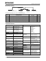
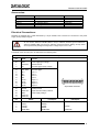
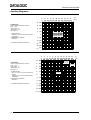
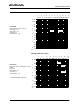
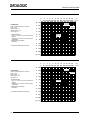
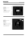
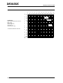
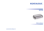
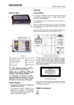
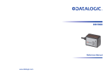
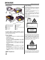
DS4600A QUICK GUIDE
General View:
Laser Safety:
12
The scanner is classified as a Class 2 laser
product according to EN 60825-1 regulations
and as a Class II laser product according to
CDRH regulations.
For installation, use and maintenance it is not
necessary to open the device.
1
11
2
DS4600A - 2XXX Models
4
5
3
There is a safety device which allows the
laser to be switched on only if the motor is
rotating above the threshold for its correct
scanning speed.
The laser beam can be switched off through a
software command (see also the WinHost
Help On-Line).
AVOID EXPOSURE
LASER LIGHT IS EMITTED
FROM THIS APERTURE
6
7
10
9
2
8
CAUTION-CLASS 3B
LASER LIGHT
WHEN OPEN
AVOID
EXPOSURE TO BEAM
DS4600A - 3XXX Models
Figure A
DATALOGIC S.p.A. Via Candini, 2
40012 LIPPO DI CALDERARA (BO) ITALY
Model No.
Serial No.
1 Cable with 25-pin Connector
7 External Trigger LED
Volt
Amp.
2 Laser Beam Output Window
8 Good Read LED
Manufactured
3 Accessory Mounting Holes
9 Ready LED
This product conforms to the applicable requirements of
21CFR1040 at the date of manufacture.
4 Warning Label
10 Warning and Classification Labels
5 Mounting Holes
11 Keypad
6 Data TX LED
12 Display
LASER LIGHT
DO NOT STARE INTO BEAM
CLASS 2 LASER PRODUCT
MAXIMUM OUTPUT RADIATION 1 mW
EMITTED WAVE LENGTH 630~680 nm
TO EN 60825-1 (2001)
For further details on product installation, see the
complete Installation Manual available on the WinHost
CD included with this product.
Power Supply:
- This product is intended to be installed by Qualified
Personnel only.
- Models DS4600A-XXX0:
This device is intended to be supplied by a UL Listed
Direct Plug-in Power Unit marked “Class 2”, rated 10-30
V minimum, 0.60 A.
This device may also be supplied by a UL Listed Power
Unit marked “Class 2” or LPS power source which
supplies power directly to the scanner via the 25-pin
connector.
- Model DS4600A-2XX5:
This device is intended to be supplied by a UL Listed
Direct Plug-in Power Unit marked “Class 2”, rated 24 V
minimum, 0.50 A.
This device may also be supplied by a UL Listed Power
Unit marked “Class 2” or LPS power source which
supplies power directly to the scanner via the 25-pin
connector.
WEEE Compliance:
Warning and device class labels
The laser diode used in this device is classified
as a class 3B laser product according to EN
60825-1 regulations and as a Class IIIb laser
product according to CDRH regulations. As it is
not possible to apply a classification label on
the laser diode used in this device, the
following label is reproduced below.
LASER LIGHT
AVOID EXPOSURE TO BEAM
CLASS 3B LASER PRODUCT
MAX. OUTPUT RADIATION 30 mW
EMITTED WAVE LENGTH 630~680 nm
TO EN 60825-1 (2001)
Laser diode class label
Any violation of the optic parts in particular
can cause radiation up to the maximum level
of the laser diode (30 mW at 630 to 680 nm).
DS4600A QUICK GUIDE
Model Description:
DS4600A - X X X X
Decoding Mode
2 = Standard w/ Display
3 = Advanced Code Reconstruction
Reading Range
0 = Medium Range
1 = Long Range
2 = Short Range
Optic Version
0 = Linear
1 = Raster R1
2 = Raster R2
Special Features
0 = Standard
5 = Integrated Heater
The following table displays each version’s reading performance.
Version
210X
200X
220X
310X
300X
320X
Reading Distance
Max Code Resolution
Speed
mm (mils)
scans/s
0.50 (20)
0.25 (10)
0.20 (8)
0.50 (20)
0.25 (10)
0.20 (8)
800
800
800
800
800
800
200 mm (8 in) - 980 mm (39 in) on 1.00 mm (40 mils) codes
160 mm (6 in) - 540 mm (21 in) on 0.50 mm (20 mils) codes
50 mm (1.97 in) - 400 mm (15.75 in) on 0.80 mm (31 mils) codes
200 mm (8 in) - 970 mm (38 in) on 1.00 mm (40 mils) codes
160 mm (6 in) - 540 mm (21 in) on 0.50 mm (20 mils) codes
120 mm (4.7 in) - 310 mm (12.2 in) on 0.30 mm (12 mils) codes
Technical Features:
ELECTRICAL FEATURES
Power Supply
Model XXX0: 10 –30 Vdc
Model 2XX5: 24 Vdc
Power Consumption Model XXX0: 6W
max.
Model 2XX5: 12W
Main Serial Interface RS232;
RS485 Full-Duplex
RS485 Half-Duplex
Auxiliary Interface
Baudrates
Inputs
External Trigger, IN1,
IN2
Voltage max.
Current Consumption
max.
Outputs
RS232
1200 to 115200
OUT1, OUT2
VCE max.
(optocoupled OE or OC)
40 Vdc
Collector Current
max.
VCE Saturation
40 mA continuous;
130 mA pulsed
1V at 10 mA max.
Power Dissipation
max.
OPTICAL FEATURES
Light Source
Wavelength
Safety Class
USER INTERFACE
LED Indicators
90 mW at 40 °C
(Ambient temp.)
(optocoupled NPN or PNP)
30 Vdc
25 mA
Headers and
Terminators
Up to four header and four
terminator characters
Operating Modes
On-Line, Automatic,
Serial-On-Line, Test
Through menus using
WinHost utility
Host Mode (commands from
one of the serial ports)
Up to six different codes
during one reading phase
Non-volatile internal
EEPROM
Configuration Modes
Semiconductor laser diode
630 to 680 nm
Class 2 - EN 60825-1; CDRH
Ready, Good Read,
External Trigger,
Data TX
PHYSICAL FEATURES
Dimensions
101x84x42 mm (4x3.3x1.7 in)
Weight
615 g. (22 oz)
2
SOFTWARE FEATURES
Readable Codes
EAN/UPC (including Add-on 2
and Add-on 5)
Code 39
2/5 Interleaved
Code 128
EAN 128
Code 93
Codabar
Pharmacode
Code Selection
Parameter Storage
ENVIRONMENTAL FEATURES
Operating
0° to 40 °C (32° to 104 °F)
Temperature
2XX5: -30° (-22 °F) to 40 °C
Storage
-20° to 70 °C (-4° to 158 °F)
Temperature
Humidity max
90% non condensing
Vibration Resistance 14 mm @ 2 to 10 Hz
IEC 68-2-6 test FC
1.5 mm @ 13 to 55 Hz
2 g @ 70 to 200 Hz
2 hours on each axis
Shock Resistance
30g; 11 ms;
IEC 68-2-27 test EA
3 shocks on each axis
Protection Class
IP65
DS4600A QUICK GUIDE
Accessories:
Name
C-BOX 100/200
C-BOX 300/310
C-BOX 400/410
GFC-41
OM4000
INT-30 (for C-Box 100)
Description
Connection Box
Connection Box Profibus
Connection Box DeviceNet
90° Reading Device
Oscillating Mirror
20 mA Current Loop Interface Board
Part Number
93ACC1510, 93ACC1520
93A301000, 93A301030
93A301010, 93A301040
91D081000
93A251030
93A151022
Electrical Connections:
DS4600A is equipped with a cable terminated by a 25-pin female D-sub connector for connection to the power
supply and input/output signals.
CAUTION
Do not connect GND and SGNDs (Main or Aux) to different (external) ground references.
GND and SGNDs (Main and Aux) are internally connected through filtering circuitry which
can be permanently damaged if subjected to voltage drops over 0.8 Vdc.
The details of the connector pins are indicated in the following table:
25-pin D-sub female connector pinout
Pin
Name
Function
13
25
1
9
18
19
6
10
14
15
8
22
11
12
20
21
23
24
16
17
VS
GND
CHASSIS
VS
EXT TRIG+
EXT TRIGIN1+
IN1IN2+
IN2OUT1 +
OUT1OUT2 +
OUT2RXAUX
TXAUX
SGND Aux
GND
Reserved
Reserved
Power supply input voltage +
Power supply input voltage Chassis Ground
External Trigger supply voltage +
External Trigger +
External Trigger Input 1 +
Input 1 Input 2 +
Input 2 Output 1 +
Output 1 Output 2 +
Output 2 Auxiliary RS232
Auxiliary RS232
Signal Ground Auxiliary interface
Power Supply Voltage -
Pin
2
3
4
5
7
RS232
TX232
RX232
RTS232
CTS232
SGND Main
25-pin female connector
RS485
Full-Duplex
TX485+
RX485+
TX485RX485SGND Main
RS485
Half-Duplex
RTX485+
RTX485SGND Main
3
DS4600A QUICK GUIDE
20
0.79
18*
20.2
83.5
3.29
0.71
0.8
14.8
0.58
M4 N°2
101
3.98
39.4
1.55
83.5
3.29
58
2.28
37
1.46
101
3.98
58
2.28
37
1.46
87.9
3.46
81
3.19
39.4
1.55
10
0.39
22*
0.86
20.2
14.8
0.58
0.8
M4 N°2
8.25
0.32
41.8
1.64
20
0.79
Mechanical Installation:
5
0.2
Mounting hole depth M4 X 5
3.75
0.15
23
0.90
42
1.65
18
0.70
3.75
0.15
37
1.47
32.5
1.28
DS4600A
18
0.70
11.8
0.46
32.5
1.28
M4 N° 4
23
0.90
42
1.65
* The quote refers to the scan line
* The quote refers to the scan line
Overall dimensions for 3XXX Models
5.5
0.22
Overall dimensions for 2XXX Models
115
4.53
Input/Output Connections:
Open Collector
C
Vext 40 Vdc max.
USER INTERFACE
8/11
+
12/22
-
5.5
0.22
DS4600A 25-pin
10°
57.3
2.26
5
0.20
5
5. 2
2
0.
39
1.54
35°
5.5
0.22
E
3
0.12
Output open collector connections
VCE max = 40 Vdc
Mounting Bracket Dimensions
I max = 40 mA continuous
NPN
Vext 30 Vdc max. USER INTERFACE
DS4600A 25-pin
+ 5V
NPN
18/6/14
+
19/10/15
-
DS4600A 25-pin
USER INTERFACE
9
VS
18/6/14
+
19/10/15
-
V
+ 5V
V
Signal
GND
25
Input NPN command using external power
Input NPN command using DS4600A power
PNP
PNP
DS4600A 25-pin
Vext 30 Vdc max.
USER INTERFACE
V
+
19/10/15
-
Signal
Ground
Input PNP command using external power
4
USER INTERFACE
DS4600A 25-pin
9
VS
18/6/14
+
19/10/15
-
V
+ 5V
+ 5V
18/6/14
Signal
Ground
25
GND
Signal
Ground
Input PNP command using DS4600A power
DS4600A QUICK GUIDE
Connectivity:
Point-to-point layout
c Main Serial Interface
dAuxiliary Serial Interface (Local Echo) (RS232)
eExternal Trigger (for On-Line Mode)
Pass-through layout
c Main Serial Interface (RS232)
dAuxiliary Serial Interface (RS232)
eExternal Trigger (for On-Line Mode)
RS232 Master/slave layout
c Main Serial Interface (Slaves RS232 only)
dAuxiliary Serial Interface (RS232)
eExternal Trigger (for On-Line Mode)
Multiplexer layout
c Main Serial Interface (RS485 Half-Duplex)
dAuxiliary Serial Interface (Local Echo) (RS232)
eExternal Trigger (for On-Line Mode)
RS485 Master/slave layout
c Auxiliary Serial Interface (RS232)
d Main Serial Interface (RS485 Half-Duplex)
eExternal Trigger
5
DS4600A QUICK GUIDE
Reading Diagrams:
DS4600A-210X (Long Range)
0
0
4
8
12
16
20
24
28
32
36
(in)
40
100 200 300 400 500 600 700 800 900 1000
(mm)
16 400
CONDITIONS
Code = Interleaved 2/5 or Code 39
PCS = 0.90
Pitch angle = 0°
Skew angle = 15°
Tilt angle = 0°
*Code Resolution:
Standard - for 0.50 mm (20 mils) codes
and greater
*Code Reading Condition:
Standard
* Parameter selectable in WinHost.
12 300
8
200
4
100
0.50 mm (20 mils)
0.60 mm (24 mils)
0.80 mm (31 mils)
1.00 mm (40 mils)
0
-4 -100
-8 -200
-12 -300
-16 -400
(in) (mm)
DS4600A-200X (Medium Range)
0
0
CONDITIONS
Code = Interleaved 2/5 or Code 39
PCS = 0.90
Pitch angle = 0°
Skew angle = 15°
Tilt angle = 0°
*Code Resolution:
High - for 0.30 mm (12 mils) codes and
smaller
Standard - for 0.50 mm (20 mils) codes
and greater
*Code Reading Condition:
Standard
* Parameter selectable in WinHost.
10
250
8
200
6
150
4
100
2
50
0
0
-2
-50
-4 -100
-6 -150
-8 -200
-10 -250
(in) (mm)
6
2
4
6
8
10
12
14
16
18
20
22
50 100 150 200 250 300 350 400 450 500 550
0.30 mm
(12 mils)
0.50 mm
(20 mils)
0.25 mm
(10 mils)
(in)
(mm)
DS4600A QUICK GUIDE
DS4600A-22XX (Short Range)
0
0
5
1
20
2
40
3
60
4
5
6
7
8
9
10
11
(in)
80 100 120 140 160 180 200 220 240 260 280 (mm)
120
4 100
3
CONDITIONS
Code = Interleaved 2/5 or Code 39
PCS = 0.90
"Pitch" angle = 0°
"Skew" angle = 10°
"Tilt" angle = 0°
*SW Resolution = High
80
60
2
40
1
20
0
0
-1
-20
* Parameter selectable in WinHost
-2
0.20 mm
(8 mils)
0.30 mm
(12 mils)
-40
-60
-3
-80
-4 -100
-5
(in)
-120
(mm)
DS4600A-22XX (Short Range)
0
10
8
CONDITIONS
Test Codes used = Interleaved 2/5 and
Code 39
PCS = 0.90
"Pitch" angle = 0°
"Skew" angle = 10°
"Tilt" angle = 0°
*SW Resolution = Low
* Parameter selectable in WinHost
6
0
2
40
4
6
8
10
12
14
16
18
20
(in)
80 120 160 200 240 280 320 360 400 440 480 520 (mm)
240
200
0.50 mm
(20 mils)
160
120
0.60 mm
(24 mils)
4
80
2
40
0
0
-2
-40
-4
≥ 0.80 mm
(31 mils)
-80
-120
-6
-160
-8 -200
-10
(in)
-240
(mm)
7
DS4600A QUICK GUIDE
DS4600A-2X1X (Raster R1)
0
0
10
250
CONDITIONS
Code = Interleaved 2/5 or Code 39
PCS = 0.90
"Pitch" angle = 0°
"Skew" angle = 18°
"Tilt" angle = 0°
8
200
6
150
4
100
*Code Resolution:
High - for 0.30 mm (12 mils) codes and
smaller
Standard - for 0.50 mm (20 mils) codes
and greater
*Code Reading Condition:
Standard
2
50
0
0
-2
-50
* Parameter selectable in WinHost.
2
4
6
8
10
12
14
16
18
20
22
50 100 150 200 250 300 350 400 450 500 550
(in)
(mm)
0.30 mm
(12 mils)
0.50 mm
(20 mils)
0.25 mm
(10 mils)
-4 -100
-6 -150
-8 -200
-10 -250
(in) (mm)
DS4600A-2X2X (Raster R2)
0
0
10
250
CONDITIONS
Code = Interleaved 2/5 or Code 39
PCS = 0.90
Pitch angle = 0°
Skew angle = 18°
Tilt angle = 0°
8
200
6
150
4
100
*Code Resolution:
High - for 0.30 mm (12 mils) codes and
smaller
Standard - for 0.50 mm (20 mils) codes
and greater
*Code Reading Condition:
Standard
2
50
0
0
-2
-50
* Parameter selectable in WinHost.
-4 -100
-6 -150
-8 -200
-10 -250
(in) (mm)
8
2
4
6
8
10
12
14
16
18
20
22
50 100 150 200 250 300 350 400 450 500 550
0.30 mm
(12 mils)
0.50 mm
(20 mils)
0.25 mm
(10 mils)
(in)
(mm)
DS4600A QUICK GUIDE
DS4600A-31XX (Long Range)
0
0
4
8
12
16
20
24
28
32
36
(in)
40
100 200 300 400 500 600 700 800 900 1000
(mm)
16 400
CONDITIONS
12 300
Code = Interleaved 2/5 and Code 39
"Pitch" angle = 0°
"Skew" angle = 15°
"Tilt" angle = 0°
*Code Resolution =
Standard for 0.50 mm (20 mils) codes
and greater
*Code Reading Conditions = Standard
8
200
4
100
0.50 mm (20 mils)
0.60 mm (24 mils)
0.80 mm (31 mils)
1.00 mm (40 mils)
0
-4 -100
-8 -200
* Parameter selectable in WinHost
-12 -300
-16 -400
(in) (mm)
DS4600A-30XX (Medium Range)
0
0
CONDITIONS
Code = Interleaved 2/5 and Code 39
PCS = 0.90
"Pitch" angle = 0°
"Skew" angle = 15°
"Tilt" angle = 0°
10
250
8
200
6
150
4
100
2
50
*Code Resolution:
High for 0.30 mm (12 mils) codes and
0
smaller
Standard for 0.50 mm (20 mils) codes
and greater
-2
*Code Reading Conditions: Standard
2
4
6
8
10
12
14
16
18
20
22
50 100 150 200 250 300 350 400 450 500 550
(in)
(mm)
0.30 mm
(12 mils)
0.50 mm
(20 mils)
0.25 mm
(10 mils)
0
-50
-4 -100
* Parameter selectable in WinHost.
-6 -150
-8 -200
-10 -250
(in) (mm)
9
DS4600A QUICK GUIDE
DS4600A-32XX (Short Range)
0
10
8
6
CONDITIONS
Code = Interleaved 2/5 and Code 39
PCS = 0.90
"Pitch" angle = 0°
"Skew" angle = 15°
"Tilt" angle = 0°
*SW Resolution: High
0
4
6
8
10
12
14
16
18
20
200
0.20 mm
(8 mils)
160
0.25 mm
(10 mils)
4
80
2
40
0
0
-2
-40
-4
-80
-120
-6
-160
-8 -200
-10
(in)
-240
(mm)
(in)
80 120 160 200 240 280 320 360 400 440 480 520 (mm)
240
120
* Parameter selectable in WinHost.
10
2
40
≥ 0.30 mm
(12 mils)
DS4600A QUICK GUIDE
User Interface:
RS232 PC-side connections
1
5
1
6
13
14
9
25-pin male connector
9-pin male connector
Pin
2
3
5
7
8
25
Name
RX
TX
GND
RTS
CTS
Pin
3
2
7
4
5
Name
RX
TX
GND
RTS
CTS
How To Build A Simple Interface Test Cable:
The following wiring diagram shows a simple test cable including power, external (push-button) trigger and PC
RS232 COM port connections.
25-pin D-sub male
9-pin D-sub female
21
TXAUX
2
RX
20
RXAUX
3
TX
5
GND
23 SGND
PC
13 VS
25 GND
DS4600A
9
VS
18 EXT TRIG+
19 EXT TRIG-
Power Supply
VS (10 – 30 Vdc)
Power GND
Trigger
Test Cable for DS4600A
11
DATALOGIC S.p.A.,
Via Candini, 2
40012 - Lippo di Calderara
Bologna - Italy
05
dichiara che
declares that the
déclare que le
bescheinigt, daß das Gerät
declare que el
DS4600A-XXXX Laser Scanner
e tutti i suoi modelli
and all its models
et tous ses modèles
und seine modelle
y todos sus modelos
sono conformi alle Direttive del Consiglio Europeo sottoelencate:
are in conformity with the requirements of the European Council Directives listed below:
sont conformes aux spécifications des Directives de l'Union Européenne ci-dessous:
der nachstehend angeführten Direktiven des Europäischen Rats:
cumple con los requisitos de las Directivas del Consejo Europeo, según la lista siguiente:
89/336/EEC EMC Directivee
and
et
und
y
92/31/EEC, 93/68/EEC emendamenti successivi
further amendments
ses successifs amendements
späteren Abänderungen
succesivas enmiendas
Basate sulle legislazioni degli Stati membri in relazione alla compatibilità elettromagnetica ed alla sicurezza dei prodotti.
On the approximation of the laws of Member States relating to electromagnetic compatibility and product safety.
Basée sur la législation des Etats membres relative à la compatibilité électromagnétique et à la sécurité des produits.
Über die Annäherung der Gesetze der Mitgliedsstaaten in bezug auf elektromagnetische Verträglichkeit und Produktsicherheit
entsprechen.
Basado en la aproximación de las leyes de los Países Miembros respecto a la compatibilidad electromagnética y las Medidas
de seguridad relativas al producto.
Questa dichiarazione è basata sulla conformità dei prodotti alle norme seguenti:
This declaration is based upon compliance of the products to the following standards:
Cette déclaration repose sur la conformité des produits aux normes suivantes:
Diese Erklärung basiert darauf, daß das Produkt den folgenden Normen entspricht:
Esta declaración se basa en el cumplimiento de los productos con las siguientes normas:
EN 55022 (CLASS A ITE), AUGUST 1994:
AMENDMENT A1 (CLASS A ITE), OCTOBER 2000:
LIMITS AND METHODS OF MEASUREMENTS OF RADIO DISTURBANCE
CHARACTERISTICS OF INFORMATION TECHNOLOGY EQUIPMENT (ITE)
EN 61000-6-2, OCTOBER 2001:
ELECTROMAGNETIC COMPATIBILITY (EMC).
PART 6-2: GENERIC STANDARDS - IMMUNITY FOR INDUSTRIAL ENVIRONMENTS
Lippo di Calderara, 08/09/2005
Ruggero Cacioppo
Quality Assurance Laboratory Manager
821000693 (Rev. D)