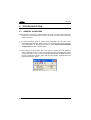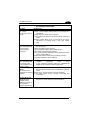
1
DS2100A Installation Manual DS2100A REFERENCE MANUAL DATALOGIC S.p.A. Via Candini 2 40012 - Lippo di Calderara di Reno Bologna - Italy DS2100A Installation Manual Ed.: 07/2004 ALL RIGHTS RESERVED Datalogic reserves the right to make modifications and improvements without prior notification. Datalogic shall not be liable for technical or editorial errors or omissions contained herein, nor for incidental or consequential damages resulting from the use of this material. Product names mentioned herein are for identification purposes only and may be trademarks and or registered trademarks of their respective companies. Datalogic S.p.A. 1998 - 2004 19/07/04 CONTENTS REFERENCES ............................................................................................. v Conventions .................................................................................................. v Reference Documentation ............................................................................ v Service, Support and Warranty ..................................................................... v SAFETY REGULATIONS............................................................................ vi Laser Safety..................................................................................................vi Power Supply...............................................................................................vii GENERAL VIEW ....................................................................................... viii GUIDE TO INSTALLATION ........................................................................ ix 1 1.1 1.1.1 1.2 1.3 INTRODUCTION .......................................................................................... 1 Product Description....................................................................................... 1 Indicators ...................................................................................................... 2 Model description.......................................................................................... 2 Accessories................................................................................................... 3 2 2.1 2.2 2.2.1 2.2.2 2.3 2.3.1 2.3.2 INSTALLATION............................................................................................ 4 Package Contents......................................................................................... 4 Mechanical Installation.................................................................................. 5 Mounting DS2100A....................................................................................... 6 Mounting the Scanner with GFC-2X00s........................................................ 7 Electrical Connections................................................................................... 9 Power Supply.............................................................................................. 10 Main Serial Interface ................................................................................... 10 RS232 Interface .......................................................................................... 11 RS485 Full-Duplex Interface ....................................................................... 12 RS485 Half-Duplex Interface ...................................................................... 13 20 mA Current Loop Interface (C-Box 100 w/INT-30 Accessory Only) ....... 15 Auxiliary RS232 Interface............................................................................ 15 Code Verifier ............................................................................................... 16 Inputs .......................................................................................................... 16 Outputs ....................................................................................................... 18 User Interface ............................................................................................. 19 Positioning .................................................................................................. 20 Typical Layouts ........................................................................................... 22 Point-to-Point .............................................................................................. 22 Pass-Through ............................................................................................. 23 RS232 Master/Slave ................................................................................... 24 RS485 Master/Slave ................................................................................... 25 2.3.3 2.3.4 2.3.5 2.4 2.5 2.6 2.6.1 2.6.2 2.6.3 2.6.4 iii 2.6.5 Multiplexer Layout....................................................................................... 26 3 3.1 3.1.1 3.1.2 3.2 3.2.1 3.2.2 3.3 3.3.1 3.4 READING FEATURES ............................................................................... 27 Advanced Code Builder (ACB).................................................................... 27 Important ACB Reading Conditions ............................................................ 28 Tilt Angle Improvement with ACB ............................................................... 29 Linear Code Reading .................................................................................. 29 Step-Ladder Mode ...................................................................................... 30 Picket-Fence Mode ..................................................................................... 31 Performance ............................................................................................... 32 Raster ......................................................................................................... 32 Reading Diagrams ...................................................................................... 33 4 4.1 MAINTENANCE ......................................................................................... 39 Cleaning...................................................................................................... 39 5 5.1 TROUBLESHOOTING................................................................................ 40 General Guidelines ..................................................................................... 40 6 TECHNICAL FEATURES ........................................................................... 43 GLOSSARY................................................................................................ 45 INDEX ......................................................................................................... 49 iv REFERENCES CONVENTIONS This manual uses the following conventions: “User” or “Operator” refers to anyone using a DS2100A. “Device” refers to the DS2100A. “You” refers to the System Administrator or Technical Support person using this manual to install, mount, operate, maintain or troubleshoot a DS2100A. REFERENCE DOCUMENTATION The documentation related to the DS2100A management is listed below: • • INT-30 20 mA Current Loop Interface Board for C-Box 100 • C-BOX 300/310 Installation Manual • • C-BOX 400/410 Installation Manual C-BOX 100 Installation Manual WinHost Help On Line SERVICE, SUPPORT AND WARRANTY Datalogic provides several services as well as technical support through its website. Log on to www.datalogic.com/services and click on the links indicated for further information including: Services – Warranty Extensions and Maintenance Agreements Downloads – Software Downloads, Manuals and Catalogues Contact Us – Listing of Datalogic Subsidiaries and Quality Partners Authorised Repair Centres v SAFETY REGULATIONS LASER SAFETY The following information is provided to comply with the rules imposed by international authorities and refers to the correct use of the DS2100A scanner. Standard Regulations This scanner utilizes a low-power laser diode. Although staring directly at the laser beam momentarily causes no known biological damage, avoid staring at the beam as one would with any very strong light source, such as the sun. Avoid that the laser beam hits the eye of an observer, even through reflective surfaces such as mirrors, etc. This product conforms to the applicable requirements of both EN 60825-1and CDRH 21 CFR 1040 at the date of manufacture. The scanner is classified as a Class 2 laser product according to EN 60825-1 regulations and as a Class II laser product according to CDRH regulations. There is a safety device which allows the laser to be switched on only if the motor is rotating above the threshold for its correct scanning speed. The laser beam can be switched off through a software command (see also the WinHost Help On Line). WARNING Use of controls or adjustments or performance of procedures other than those specified herein may result in exposure to hazardous visible laser light. The laser light is visible to the human eye and is emitted from the window on the front of the scanner (Figure A, 8). vi Warning labels indicating exposure to laser light and the device classification are applied onto the body of the scanner (Figure A, 6). LASER LIGHT DO NOT STARE INTO BEAM CLASS 2 LASER PRODUCT MAX. OUTPUT RADIATION 1 mW EMITTED WAVE LENGTH 630~680 nm TO EN 60825-1:2001 N2468 218441 CAUTION-CLASS 3B LASER LIGHT WHEN OPEN AVOID EXPOSURE TO BEAM R C US This product conforms to the applicable requirements of 21CFR1040 at the date of manufacture. Warning and Device Class Labels Disconnect the power supply when opening the device during maintenance or installation to avoid exposure to hazardous laser light. The laser diode used in this device is classified as a class 3B laser product according to EN 60825-1 regulations and as a Class IIIb laser product according to CDRH regulations. As it is not possible to apply a classification label on the laser diode used in this device, the following label is reproduced on the right. LASER LIGHT AVOID EXPOSURE TO BEAM CLASS 3B LASER PRODUCT MAX. OUTPUT RADIATION 35 mW EMITTED WAVE LENGTH 630~680 nm TO EN 60825-1 (2001) Laser Diode Class Label Any violation of the optic parts in particular can cause radiation up to the maximum level of the laser diode (35 mW at 630 to 680 nm). POWER SUPPLY - This product is intended to be installed by Qualified Personnel only. - All Models: This accessory device is intended to be supplied by a UL Listed or CSA Certified Power Unit with «Class 2» or LPS power source which supplies power directly to the scanner via the 25-pin connector. vii GENERAL VIEW DS2100A 1 2 3 4 5 6 7 8 Figure A viii 1 Mounting Holes 5 Power On / Data TX LED 2 Laser On LED 6 Warning and Device Class Labels 3 Good Read LED 7 Accessory Mounting Holes 4 External Trigger LED 8 Laser Beam Output Window GUIDE TO INSTALLATION The following can be used as a checklist to verify all of the steps necessary for complete installation of the DS2100A scanner. 1) Read all information in the section "Safety Precautions” at the beginning of this manual. 2) Correctly mount the reader using the bracket provided according to the information in par.2.2.1. 3) Position the reader at the correct reading distance according to your model as shown in paragraphs 2.2.1,2.5 and 3.3. 4) Make electrical connections to your DS2100A scanner by either: a) Connecting the test cable to the DS2100A scanner as described in par.2.4. b) Providing correct and complete system cabling according to the signals necessary for the layout of your application. • Layout: Point-to-point, RS485 Master/Slave, RS232 Master/Slave, Multiplexer. See sub-paragraphs under 2.6 for reference. • Cabling: Power, Main Serial Interface, Auxiliary Interface (RS232), Inputs, Outputs, etc. For further details, see all sub-paragraphs under 2.3. 5) Configure the DS2100A scanner by installing and running the WinHost configuration program from the CD- ROM provided. The main steps are: • • • • Select the codes to be read Set-up the communication parameters Define data formatting parameters Fine tune your DS2100A scanner using the Test Mode as described in WinHost. Specific parameter details are available in the Help On Line. See also the Guide To Rapid Configuration link. 6) Exit the configuration program and run your application. The installation is now complete. ix x INTRODUCTION 1 1 INTRODUCTION 1.1 PRODUCT DESCRIPTION The DS2100A laser scanner satisfies the most advanced needs of a wide range of users. It has been developed focusing on the realistic requirements of its target market. The outstanding result is an extremely compact, cost-effective and easy to use industrial scanner. Standard Application Program A standard application program is factory-loaded onto the DS2100A. This program controls barcode reading, serial port interfacing, data formatting and many other operating and control parameters. It is completely configurable from a host computer through the WinHost utility program provided on CD with the scanner, or through ESC sequences via the serial interface. Custom Application Programs If the Standard Application Program does not meet your requirements, please contact your local Datalogic distributor. Some of the main features of DS2100A are listed below: • ACB (Advanced Code Builder). • small dimensions and light weight. • software programmable scanning speed on all models. • linear and raster version. • Completely configurable via serial interface (WinHost™). • 2 serial communication interfaces. • supply voltage from 10 to 30 Vdc. • reads all popular codes. • test mode to verify the reading features and exact positioning of the scanner without the need for external tools. • programmable in 4 different operating modes to suit the most various barcode reading system requirements. • code verifier • low power consumption. 1 DS2100A 1 The DS2100A uses a solid state laser diode as a light source; the light emitted has a wavelength between 630 and 680 nm. Refer to the section “Safety precautions” at the beginning of this manual for information on laser safety. The protection class of the enclosure is IP65, the reader is therefore suitable for industrial environments where high protection against harsh external conditions is required. 1.1.1 Indicators The four LEDs on the side of the scanner indicate the following: PWR/TXD LED (red) (Figure A, 5) indicates the reader is connected to the power supply or, when blinking (green), data transmission. GOOD READ LED (red) (Figure A, 3) is used to signal the possibility of a successful barcode reading. EXT TRIG LED (yellow) (Figure A, 4) indicates external trigger activity. Refer to par. 2.3.4. LASER ON LED (green) (Figure A, 2) indicates laser ON state. The screw holes on the body of the reader are for mechanical fixture (Figure A, 1). 1.2 MODEL DESCRIPTION The DS2100A scanner is available in versions that differ in regard to the following parameters: • Resolution • Performance • Linear or raster reading DS2100A - X X X X Optical Resolution Performance 1 = Standard Resolution 2 = High Resolution 0 = Standard 4 = Testarossa™ Communication Interface Optic Version 2 = RS232/RS485main + RS232 aux 0 = Linear 1 = Raster 2 INTRODUCTION 1 The following tables display each version’s reading performance. Version 12X0 12X4 22X0 22X4 Version 12X0 12X4 22X0 2XX4 Max Code Resolution Speed mm (mils) 0.20 (8) 0.15 (6) 0.15 (6) 0.12 (5) scans/s 500 to 800 800 to 1000 500 to 800 800 to 1000 Reading Distance 40 mm 50 mm 30 mm 45 mm (1.6 in) - 300 mm (11.8 in) on 0.50mm (20 mils) codes (1.8 in) - 310 mm (11.8 in) on 0.50 mm (20 mils) codes (1.2 in) - 90 mm (3.5 in) on 0.30 mm (12 mils) codes (1.8) – 100 mm (3.9 in) on 0.20 mm (8 mils) codes See reading diagrams in par. 3.4 for further details. 1.3 ACCESSORIES The following accessories are available on request for the DS2100A: Name GFC-2100 GFC-2000 INT-30 (for C-Box 100) C-BOX 100/200 C-BOX 300/310 C-BOX 400/410 MEP-542/543 Description 90° Reading Device 75° reading Device 20 mA Current Loop Interface Board Part Number 93A201000 93A201080 93A151022 Connection Box Connection Box Profibus Connection Box DeviceNet Photocell kit NPN/PNP 93ACC1510, 93ACC1520 93A301000, 93A301030 93A301010, 93A301040 93ACC1727, 93ACC1728 3 DS2100A 2 2 INSTALLATION 2.1 PACKAGE CONTENTS Verify that the DS2100A reader and all the parts supplied with the equipment are present and intact when opening the packaging; the list of parts includes: • DS2100A reader with cable • Installation manual • Bar code test chart (PCS = 0.9) • • WinHost CD-ROM Mounting kit: - bracket - screws Figure 1 - DS2100A Package Contents 4 INSTALLATION 2.2 2 MECHANICAL INSTALLATION DS2100A can be installed to operate in different positions. The four screw holes (M4 x 5) on the body of the reader are for mechanical fixture (Figure A, 1). The diagrams below give the overall dimensions of the scanner and mounting bracket and may be used for installation. Refer to par. 2.5 for correct positioning. DS2100A 83.6 3.29 23.3* 0.92 40 1.57 10.3 0.4 5 0.098 68 2.68 46 1.81 40 1.57 10.3 0.4 14.5 0.57 14.6 0.57 M 4 n° 4 34 1.3 DS2100A DS2100 mm inch The quote refers to the scan line MOUNTING BRACKET 9 30 17.5 40 4.2 n° 2 2.5 4.2 20° 13.8 R 42 90° 1 x 45° n° 2 7.8 4.2 73 23 2.5 * mm Figure 2 - Overall Dimensions 5 DS2100A 2 2.2.1 Mounting DS2100A Using the DS2100A mounting bracket you can obtain the most suitable position for the reader as shown in the figure below: Tilt Skew Skew Pitch Figure 3 – Positioning with Mounting Bracket 6 INSTALLATION 2.2.2 2 Mounting the Scanner with GFC-2X00s GFC-2X00s are deflection mirrors available on request for DS2100A. • The GFC-2000 is a 75° deflection mirror • The GFC-2100 is a 90° deflection mirror The reading position with respect to the scanner is shown below for each mirror. GFC-2000 75° ± 2° Laser Beam 90° ± 2° GFC-2100 Figure 4 - GFC-2X00 Laser Beam Output Position 7 DS2100A 2 The installation of the deflection mirror is very easy (Figure 5). CAUTION Avoid any contact with the deflection mirror, mirrored rotor, the lenses or other optical components, otherwise the performance of the reader will be reduced. 1. Turn off the device. 2. Remove the DS2100A scanning window unscrewing the two cover screws. 3. Fix the mirror to the device by means of the two fixing screws. 4. Remount the scanning window so that the opening face is now at 90° with respect to the DS2100A body. deflection mirror Cover screws Scanning window Fixing screws Figure 5 - Installation of the Deflection Mirror 8 INSTALLATION 2.3 2 ELECTRICAL CONNECTIONS All DS2100A models are equipped with a cable terminated by a 25-pin female D-sub connector for connection to the power supply and input/output signals. The details of the connector pins are indicated in the following table. CAUTION Do not connect GND and SGND to different (external) ground references. GND and SGND are internally connected through filtering circuitry which can be permanently damaged if subjected to voltage drops over 0.8 Vdc. Figure 6 - 25-pin Female D-sub Connector 25-pin D-sub connector pinout Pin 13 25 1 9 18 19 8 11 12, 22 20 21 23 24 6, 10, 14, 15, 16, 17 Name Function VS GND CHASSIS VS EXT TRIG+ EXT TRIGOUT1 + OUT2 + OUT REF RXAUX TXAUX CTSAUX RTSAUX NC Power supply input voltage + Power supply input voltage Chassis Ground External Trigger supply voltage + External Trigger + External Trigger Output 1 + Output 2 + Output reference Auxiliary RS232 Auxiliary RS232 Auxiliary handshake RS232 Auxiliary handshake RS232 Not Connected Pin 2 3 4 5 7 RS232 Main interface signals, see par. 2.3.2. TX232 RX232 RTS232 CTS232 SGND RS485 Full-Duplex TX485+ RX485+ TX485RX485SGND RS485 Half-Duplex RTX485+ RTX485SGND 9 DS2100A 2 2.3.1 Power Supply Power can be supplied to the scanner through the pins provided on the 25-pin connector used for communication with the host (Figure 7): USER INTERFACE DS2100A 13 VS V+ (10 - 30 Vdc) 25 GND 1 VGND CHASSIS CHASSIS Earth Ground Figure 7 - Power Supply Connections The power must be between 10 and 30 Vdc only. It is recommended to connect pin 1 (CHASSIS) to a common earth ground. 2.3.2 Main Serial Interface The signals relative to the following serial interface types are available on the input/output connector of DS2100A. If the interface type is not compatible with the current communication handshaking, then the system forces the handshake to none. The main interface type and the relative parameters (baud rate, data bits, etc.) can be set using the WinHost utility program or "Host Mode Programming” procedure through ESC sequences. Details regarding the connections and use of the interfaces are given in the next paragraphs. 10 INSTALLATION 2 RS232 Interface The serial interface is used in this case for point-to-point connections; it handles communication with the host computer and allows both transmission of code data and the programming of the scanner. This is the default setting. The following pins are used for RS232 interface connection: Pin 2 3 4 5 7 Name TX232 RX232 RTS232 CTS232 SGND Function transmit data receive data request to send clear to send signal ground It is always advisable to use shielded cables. The overall maximum cable length must be less than 15 m (49.2 ft). DS2100A Chassis USER INTERFACE 2 TX232 3 RX232 4 RTS232 5 CTS232 7 SGND RXD TXD DCD DTR SGND 1 Figure 8 – RS232 Main Interface Connections Using Hardware Handshaking The RTS232 and CTS232 signals control data transmission and synchronize the connected devices. 11 DS2100A 2 START OF TRANSMISSION END OF TRANSMISSION +V RTS -V DATA TRANSMISSION DATA TRANSMISSION +V TX DATA -V C1 C2 C3 C4 C5 TRANSMISSION STOPPED ENABLED +V CTS -V ENABLED DISABLED IDLE IDLE Figure 9 - RS232 Control Signals If the RTS/CTS handshaking protocol is enabled, the DS2100A activates the RTS232 output to indicate a message is to be transmitted. The receiving unit activates the CTS232 input to enable the transmission. RS485 Full-Duplex Interface The RS485 full-duplex (5 wires + shield) interface is used for non-polled communication protocols in point-to-point connections over longer distances (max 1200 m / 3940 ft) than those acceptable for RS232 communications or in electrically noisy environments. The connector pinout follows: Pin 2 4 3 5 7 12 Name Function TX485+ TX485RX485+ RX485SGND RS485 transmit data + RS485 transmit data RS485 receive data + RS485 receive data signal ground INSTALLATION 2 DS2100A USER INTERFACE 2 TX485+ 4 TX485- 3 RX485+ 5 RX485- 7 SGND Chassis + RX485 + TX485 + SGND 1 Figure 10 - RS485 Full-duplex Connections RS485 Half-Duplex Interface The RS485 half-duplex (3 wires + shield) interface is used for polled communication protocols. It can be used in a master/slave layout or for Multidrop connections with a Datalogic Multiplexer, (see par. 2.6.4 and 2.6.5) exploiting a proprietary protocol based on polled mode called MUX32 protocol, where a master device polls slave devices to collect data. The connector pinout follows: Pin 2 4 7 Name Function RTX485+ RTX485SGND RS485 transmit/receive data + RS485 transmit/receive data signal ground DS2100A Chassis MULTIPLEXER 2 RTX485 + 4 RTX485 - 7 SGND RTX485 + RTX485 RS485REF 1 Figure 11- RS485 Half-duplex Connections This interface is forced by software when the protocol selected is MUX32 protocol. 13 DS2100A 2 In a Multiplexer layout or for slaves, the Multidrop address must also be set via serial channel by the WinHost utility or by ESC sequences. Figure 1 shows a multidrop configuration with DS2100A scanners connected to a Multiplexer. This is an example of multidrop wiring. Consult the multiplexer manual for complete wiring instructions. CAUTION 120 Ohm max 2 m DS2100A #x (up to 31) max 1200 m DS2100A #1 RTX485 + DS2100A #0 CHASSIS RTX485 SGND Three wires + shield RTX485 + RTX485 MULTIPLEXER RS485 REF SHIELD 120 Ohm Figure 12 - DS2100A Multidrop Connection to a Multiplexer 14 INSTALLATION 2 20 mA Current Loop Interface (C-Box 100 w/INT-30 Accessory Only) To adapt DS2100A to 20 mA current loop interfaces, it must be connected to a C-Box 100 which is equipped with an INT-30 (20 mA current loop adapter accessory board). The INT-30 converts 20 mA current loop signals into RS232 signals to the scanner. See the C-Box 100 Installation Manual and the INT-30 instructions. 2.3.3 Auxiliary RS232 Interface The auxiliary serial interface is used exclusively for RS232 point-to-point connections. The parameters relative to the aux interface (baud rate, data bits, etc.) as well as particular communication modes such as LOCAL ECHO can be defined using the WinHost utility program or "Host Mode Programming", installed from the CD-ROM. The following pins of the 25-pin connector are used to connect the RS232 auxiliary interface: Pin 20 21 23 24 7 Name RXAUX TXAUX CTSAUX RTSAUX SGND DS2100A Chassis Function receive data Transmit data clear to send Request to send signal ground USER INTERFACE 20 RXAUX 21 TXAUX 23 CTSAUX 24 RTSAUX 7 SGND TXD RXD DTR DCD SGND 1 Figure13- RS232 Auxiliary Interface Connections Using Hardware Handshaking 15 DS2100A 2 When the auxiliary interface is permanently connected as part of the system cabling, it is recommended to connect the cable shield to earth ground. The RTSAUX and CTSAUX signals control data transmission and synchronize the connected devices. If the RTS/CTS handshaking protocol is enabled, the DS2100A activates the RTSAUX output to indicate a message is to be transmitted. The receiving unit activates the CTSAUX input to enable the transmission. Code Verifier If the DS2100A is used as a Code Verifier, it is possible to indicate to the scanner what code to store as the verifier code by means of an external hardware input. The Code Verifier parameter must be enabled and the configuration parameters to allow correct Code Type reading must be saved to the scanner in order to read the verifier code. To activate the input, connect together pins 23 and 24 (CTSAUX and RTSAUX) of the 25-pin connector (for example with a push-button), before the active edge of the External Trigger input (or before the code passes under the laser beam for the Automatic operating mode). The next read code will be stored as the verifier code in the scanner's RAM and NON-VOLATILE (EEPROM) memory by default. Then, the two pins must be disconnected. Since it uses part of the RS232 auxiliary serial interface, this interface is limited when using this option and the Handshake selection must not be set to RTS/CTS. 2.3.4 Inputs The inputs available on the connector supplied with the scanner are the pins relative to the External Trigger, as indicated below: Pin Name Function 18 19 EXT TRIG+ EXT TRIG- external trigger + external trigger - The External Trigger input is used in the On-Line operating Mode and tells the scanner to scan for a code. The active state of this input is selected in software. Refer to the WinHost Help On Line. 16 INSTALLATION 2 The yellow LED (Figure A, 4) is on when the External Trigger forces a current flow through the EXT TRIG+ and EXT TRIG- pins. This input is optocoupled and can be driven by both an NPN or PNP type command. The connections are indicated in the following diagrams: DS2100A Vext + 5V 18 EXT TRIG+ 19 EXT TRIG- 30 Vdc max. EXTERNAL TRIGGER V Signal Figure 14- Input NPN Command Using External Power DS2100A EXTERNAL TRIGGER 9 + 5V VS V 18 EXT TRIG+ 19 EXT TRIG25 GND Signal Ground Figure 15 - Input NPN Command Using DS2100A Power DS2100A MEP-543 Connector 9 + 5V VS 18 EXT TRIG+ (brown) (white) 2 1 3 4 19 EXT TRIG25 GND (blue) Figure 16 - Input NPN Command Using MEP-543 Photocell 17 DS2100A 2 Vext 30 Vdc max. DS2100A EXTERNAL TRIGGER V + 5V Signal 18 EXT TRIG+ 19 EXT TRIG- Ground Figure 17- Input PNP Command Using External Power EXTERNAL TRIGGER DS2100A 9 + 5V VS V 18 EXT TRIG+ 19 EXT TRIG- 25 Signal GND Ground Figure 18- Input PNP Command Using DS2100A Power Electrical features: Maximum voltage: Maximum current: 30 Vdc 25 mA An anti-disturbance hardware filter is implemented on the External Trigger input (< 5 milliseconds delay). An additional 15 ms (typical) delay can be implemented through a dedicated software parameter (refer to WinHost Help On Line). 2.3.5 Outputs Two general purpose outputs are available. These outputs can only be connected as open collector configurations. The following pins are present on the 25-pin connector of the scanner: Pin 8 11 12, 22 Name OUT1+ OUT2+ OUT REF Function output 1 + output 2 + output reference The meaning of the two outputs OUT1 and OUT2 can be defined by the user (No Read, Right or Wrong). Refer to the WinHost Help On Line. 18 INSTALLATION 2 By default, OUT1 is associated with the No Read event, which activates when the code signaled by the external trigger is not decoded, and OUT2 is associated with the Right event, which activates when the code is correctly decoded. These outputs are both level or pulse configurable. DS2100A USER INTERFACE 8/11 12/22 Vext 40 Vdc max OUT1+ / OUT2+ OUT REF Figure 19- Output Open Collector Connections VCE max = 40 Vdc I max = 40 mA continuous 2.4 USER INTERFACE The following table contains the pinout for standard RS232 PC Host interface. For other user interface types please refer to their own manual. RS232 PC-side connections 1 5 1 6 14 9 9-pin male connector Pin 2 3 5 7 8 Name RX TX GND RTS CTS 13 25 25-pin male connector Pin 3 2 7 4 5 Name RX TX GND RTS CTS 19 DS2100A 2 How To Build A Simple Interface Test Cable: The following wiring diagram shows a simple test cable including power, external (push-button) trigger and PC RS232 COM port connections. 25-pin D-sub male 9-pin D-sub female 21 TXAUX 2 RX 20 RXAUX 3 TX 7 SGND 5 GND 13 VS PC 25 GND DS2100A 9 VS 18 EXT TRIG+ 19 EXT TRIG- Power Supply VS (10 – 30 Vdc) Power GND Trigger Test Cable for DS2100A 2.5 POSITIONING The DS2100A scanner is able to decode moving barcode labels at a variety of angles, however significant angular distortion may degrade reading performance. When mounting the DS2100A take into consideration these three ideal label position angles: Pitch 0°, Skew 10° to 30° and Tilt 0°. Follow the suggestions for the best orientation: The Pitch angle is represented by the value P in Figure 20. Position the reader in order to minimize the Pitch angle. P Figure 20- Pitch Angle 20 INSTALLATION 2 The Skew angle is represented by the value S in Figure 21. Position the reader to assure at least 10° for the Skew angle. This avoids the direct reflection of the laser light emitted by the DS2100A. For the raster version, this angle refers to the most inclined or external raster line, so that all other raster lines assure more than 10° Skew. S Figure 21- Skew Angle The Tilt angle is represented by the value T in Figure 22. Position the reader in order to minimize the Tilt angle. T Figure 22 - Tilt Angle By using the ACB (Advanced Code Builder) software parameter, the tilt angle is less critical and can be decoded even if the scan line doesn’t cross the entire code. See par. 3.1 or the Help On Line for details. 21 DS2100A 2 2.6 TYPICAL LAYOUTS The following typical layouts refer to system hardware configurations. Dotted lines in the figures refer to optional hardware configurations within the particular layout. These layouts also require the correct setup of the software configuration parameters. Complete software configuration procedures can be found in the Guide To Rapid Configuration in the WinHost Help On Line. 2.6.1 Point-to-Point In this layout the data is transmitted to the Host on the main serial interface. Host Mode programming can be accomplished either through the main interface or the Auxiliary interface. In Local Echo communication mode, data is transmitted on the RS232 auxiliary interface independently from the main interface selection. When On-Line Operating mode is used, the scanner is activated by an External Trigger (photoelectric sensor) when the object enters its reading zone. 2 1 DS2100A Terminal Host 3 1 Main serial interface 2 Auxiliary serial interface (Local Echo) 3 External Trigger (for On-Line mode) Figure 23– Point-to-Point Layout 22 INSTALLATION 2.6.2 2 Pass-Through Pass-through mode allows two or more devices to be connected to a single external serial interface. Each DS2100A transmits the messages received by the Auxiliary interface onto the Main interface. All messages will be passed through this chain to the host. When On-Line Operating mode is used, the scanner is activated by an External Trigger (photoelectric sensor) when the object enters its reading zone. The Main and Auxiliary ports are connected as shown in the figure below: 2 DS2100A 1 DS2100A 1 Host 3 3 1 Main serial interface 2 Auxiliary serial interface 3 External Trigger (for On-Line mode) Figure 24 – Pass-Through Layout 23 DS2100A 2 2.6.3 RS232 Master/Slave The RS232 master/slave connection is used to collect data from several scanners to build either a multi-point or a multi-sided reading system; there can be one master and up to 9 slaves connected together. The Slave scanners use RS232 only on the main and auxiliary serial interfaces. Each slave DS2100A transmits the messages received by the auxiliary interface onto the main interface. All messages will be passed through this chain to the Master. The Master scanner is connected to the Host on the main serial interface. The possible main interface types for the master scanner are RS232 or RS485. (20 mA C.L. can also be used if the INT-30 with C BOX 100 accessory is installed). There is a single reading phase and a single message from the master scanner to the Host computer. Either On-Line or Serial On-Line Operating modes can be used in this layout. When On-Line Operating mode is used, the external trigger signal is unique to the system, however it is not necessary to bring the external trigger signal to the Slave scanners. The main and auxiliary ports are connected as shown in the figure below. 1 2 DS2100A Slave 2 DS2100A Slave DS2100A Master 1 1 3 Host 1 Main serial interface 2 Auxiliary serial interface 3 External Trigger (for On-Line mode) Figure 25 – RS232 Master/Slave Layout 24 INSTALLATION 2.6.4 2 RS485 Master/Slave The RS485 master/slave connection is used to collect data from several scanners to build a multi-point or a multi-sided reading system; there can be one master and up to 5 slaves connected together. The slave scanners are connected together using RS485 half-duplex on the main serial interface. Every slave scanner must have a multidrop address in the range 0-4. The master scanner is also connected to the Host on the RS232 auxiliary serial interface. The External Trigger signal is unique to the system; there is a single reading phase and a single message from the master scanner to the Host computer. It is necessary to bring the External Trigger signal to all the scanners. The main and auxiliary ports are connected as shown in the figure below. 1 Auxiliary serial interface 1 Host 2 RD485HD Main serial interface 3 External Trigger 2 1 DS2100A Slave DS2100A Slave DS2100A Master 1 3 Figure 26 – RS485 Master/Slave Layout The auxiliary serial interface of the slave scanners can be used in Local Echo communication mode to control any single scanner (visualize collected data) or to configure it using the WinHost utility or Host Mode programming procedure. NOTE The termination resistors of the RS485 bus must not be installed. 25 DS2100A 2 2.6.5 Multiplexer Layout Each scanner is connected to a Multiplexer (for example MX4000) with the RS485 half-duplex main interface. 31 1 0 2 2 3 2 3 3 1 Host 1 Main interface 2 Auxiliary interface (Local Echo) MX4000 3 External Trigger (for On-Line mode) Figure 27 - Multiplexer Layout The auxiliary serial interface can be used in Local Echo communication mode to control any single scanner (visualize collected data) or to configure it using the WinHost utility or Host Mode programming procedure. When On-Line Operating mode is used, the scanner is activated by an External Trigger (photoelectric sensor) when the object enters its reading zone. 26 READING FEATURES 3 3.1 3 READING FEATURES ADVANCED CODE BUILDER (ACB) In addition to linear reading, the Advanced Code Builder (ACB) allows code reading by “stitching” together two partial reads of it. ACB is not as powerful as Advanced Code Reconstruction due to limits on tilt angle, speed and Multi-label function; but it is effective in the case of close-to-linear, small height codes, damaged codes, or poor print quality codes. ACB is used to read a code label when the scan line does not cross the label along its entire length (excessive tilt angle). iQk iQk iQk iQk iQk iQk iQk iQk iQk iQk iQk iQk iQk iQk iQk iQk Linear Reading Linear Reading iQk iQk iQk iQk iQk iQk iQk iQk ACB Reading ACB Reading ACB reads two fragments of a label containing a start or a stop character and a number of digits, and puts them together to build the complete label. ACB also has an intrinsic ability to increase the reading percentage of damaged codes as in the examples below: iQk iQk iQk iQk iQk iQk iQk iQk ACB Readable iQk iQk iQk iQk iQk iQk iQk iQk Not ACB Readable 27 DS2100A 3 ACB Readable ACB is disabled by default but can be enabled for the following code types: • • • 3.1.1 Code 25 Interleaved Code 39 Family Codabar • • • Code 128/EAN128 EAN/UPC (without ADD-Ons) Code 93 Important ACB Reading Conditions • Do not use ACB for omni-directional reading stations. • ACB can be activated for each symbology independently from the others. • ACB requires that the code be in movement with respect to the scanner. • ACB requires fixed length barcode reading. • The codes read with ACB enabled must pass in front of the scanner one at a time. Not valid for ACB Valid for ACB • Code concatenation and ACB are not compatible and therefore cannot be enabled simultaneously on the same code. • For correct operation, ACB requires at least 5 scans for each of the two fragments 28 READING FEATURES 3.1.2 3 Tilt Angle Improvement with ACB ACB allows barcode reading with an increased tilt angle. The tilt angle depends upon the code aspect ratio defined as H/L according to the table below: L H Aspect Ratio H/L 0.33 0.25 0.125 3.2 barcode label Max theoretical linear tilt angle 18° 14° 7° Max practical ACB angle 30° 23° 11° LINEAR CODE READING The number of scans performed on the code by the DS2100A and therefore the decoding capability is influenced by the following parameters: • • • • number of scans per second code motion speed label dimensions scan direction with respect to code motion At least 5 scans during the code passage should be allowed to ensure a successful read. 29 DS2100A 3 3.2.1 Step-Ladder Mode If scanning is perpendicular to the code motion direction (Figure 28), the number of effective scans performed by the reader is given by the following formula: SN = [(LH/LS) * SS] – 2 Where: SN = number of effective scans LH LS SS = label height (in mm) = label movement speed in (mm/s) = number of scans per second Direction of code movement at LS speed DS2100A LH Laser beam Figure 28 - "Step-Ladder" Scanning Mode For example, the DS2100A (500 scans/sec.) for a 25 mm high code moving at 1000 mm/s performs: [(25/1000) * 500] - 2 = 10 effective scans. 30 READING FEATURES 3.2.2 3 Picket-Fence Mode If scanning is parallel to the code motion, (Figure ), the number of effective scans is given by the following formula: SN = [((FW-LW)/LS) * SS] -2 Where: SN = number of effective scans FW = reading field width (in mm) LW = label width (in mm) LS = label movement speed (in mm/s) SS = scans per second Direction of code movement at LS speed DS2100A LW Laser beam FW Figure 29 - "Picket-Fence" Scanning Mode For example, for a 60 mm wide code moving in a point where the reading field is 160 mm wide at a 1500 mm/s speed, the DS2100A (500 scans per sec.), performs: [((160-60)/1500) * 500] - 2 = 31 effective scans 31 DS2100A 3 3.3 PERFORMANCE The DS2100A scanner is available in different versions according to the reading performance. Version 12X0 12X4 22X0 22X4 Max Code Resolution Speed mm (mils) 0.20 (8) 0.15 (6) 0.15 (6) 0.12 (5) scans/s 500 to 800 800 to 1000 500 to 800 800 to 1000 Version Reading Distance 12X0 12X4 22X0 22X4 40 mm (1.6 in) - 300 mm (11.8 in) on 0.50 mm (20 mils) codes 50 mm (1.8 in) - 310 mm (11.8 in) on 0.50 mm (20 mils) codes 30 mm (1.2 in) - 90 mm (3.5 in) on 0.30 mm (12 mils) codes 45 mm (1.8 in) - 100 mm (3.9 in) on 0.20 mm (8 mils) codes Refer to the diagrams given in par. 3.4 for further details on the reading features. They are taken on various resolution sample codes at a 25 °C ambient temperature, depending on the conditions in the notes under the diagrams. 3.3.1 Raster Raster versions are available. If standard devices do not satisfy specific requirements, contact your nearest Datalogic distributor, supplying code samples, to obtain complete information on the reading possibilities. The reading characteristics for the raster version is given in the table below. The distance between the top and bottom scan lines is given at different reading distances measured from the laser beam output window. Reading Distance Raster Capture 300 mm (11.8 in) 600 mm (23.6 in) 18 mm (0.7 in) 35 mm (1.4 in) The max. capture of the Raster version is 18 mm (0.7 in) at 300 mm (11.8 in). 32 READING FEATURES 3.4 3 READING DIAGRAMS DS2100A-1200 (Standard Resolution, 500 scans/s) 0 0 5 4 3 1 20 2 40 3 60 4 5 6 7 8 9 10 11 12 (in) 80 100 120 140 160 180 200 220 240 260 280 300 (mm) 120 100 80 60 2 40 1 20 0 0 1 20 2 0.20 mm (8 mils) 0.30 mm (12 mils) 0.35 mm (14 mils) ≥ 0.50 mm (20 mils) 40 60 3 4 5 (in) 80 100 120 (mm) NOTE: (0,0) is the center of the laser beam output window. CONDITIONS Optic Version = Linear Code = Interleaved 2/5 or Code 39 PCS = 0.90 "Pitch" angle = 0° "Skew" angle = 15° "Tilt" angle = 0° *Code Reading Condition = Standard * Parameter selectable in Winhost 33 DS2100A 3 DS2100A-1200 Reading Distance vs Scanning Speed Distance 0 0 1 20 2 40 60 3 4 5 6 7 8 9 10 11 12 0.50 mm 0.35 mm 0.30 mm 0.20 mm 500 scans/s Code Resolution 34 (in) 80 100 120 140 160 180 200 220 240 260 280 300 (mm) 800 scans/s READING FEATURES 3 DS2100A-2200 (High resolution, 500 scans/s) 0 0 1 10 20 2 30 40 50 3 60 70 4 80 5 90 100 110 120 130 (in) (mm) 60 2 50 40 30 ≥ 0.30 mm (12 mils) 1 20 10 0 0.15 mm (6 mils) 0 10 20 1 30 0.20 mm (8 mils) 40 2 (in) 50 60 (mm) NOTE: (0,0) is the center of the laser beam output window. CONDITIONS Optic Version = Linear Code = Interleaved 2/5 or Code 39 PCS = 0.90 "Pitch" angle = 0° "Skew" angle = 15° "Tilt" angle = 0° *Code Reading Condition = Standard * Parameter selectable in Winhost 35 DS2100A 3 DS2100A-2200 Reading Distance vs Scanning Speed Distance 0 0 1 10 20 2 30 40 50 3 60 70 4 80 5 90 100 110 120 130 0.30 mm 0.20 mm 0.15 mm 500 scans/s Code Resolution 36 800 scans/s (in) (mm) READING FEATURES 3 DS2100A-1204 Testarossa™ (Standard Resolution, 1000 scans/s) 0 0 5 4 3 1 20 2 40 3 60 4 5 6 7 8 9 10 11 12 (in) 80 100 120 140 160 180 200 220 240 260 280 300 (mm) 120 100 80 60 2 40 1 20 0 0 1 20 2 0.15 mm (6 mils) 0.20 mm (8 mils) 0.30 mm (12 mils) ≥ 0.50 mm (20 mils) 40 60 3 80 4 100 5 (in) 120 (mm) NOTE: (0,0) is the center of the laser beam output window. CONDITIONS Optic Version = Linear Code = Interleaved 2/5 or Code 39 PCS = 0.90 "Pitch" angle = 0° "Skew" angle = 15° "Tilt" angle = 0° *Code Resolution = High for 0.30 mm, (12 mils) codes and smaller Standard for 0.50 mm (20 mils) codes and greater *Code Reading Condition = Standard * Parameters selectable in Winhost 37 DS2100A 3 DS2100A-2204 Testarossa™ - (High Resolution, 1000 scans/s) 0 0 1 10 20 2 30 40 50 3 60 70 4 80 5 90 100 110 120 130 60 2 50 40 30 ≥ 0.20 mm (8 mils) 1 20 10 0 0.12 mm (5 mils) 0 10 20 1 30 40 2 (in) 50 60 (mm) NOTE:(0,0) is the center of the laser beam output window. CONDITIONS Optic Version = Linear Code = Interleaved 2/5 or Code 39 PCS = 0.90 "Pitch" angle = 0° "Skew" angle = 15° "Tilt" angle = 0° *Code Resolution = High for 0.15 mm (6 mils) codes and smaller Standard for 0.20 mm (8 mils) codes *Code Reading Condition = Standard * Parameters selectable in Winhost 38 0.15 mm (6 mils) (in) (mm) MAINTENANCE 4 4.1 4 MAINTENANCE CLEANING Clean the laser beam output window periodically for continued correct operation of the reader. Dust, dirt, etc. on the window may alter the reading performance. Repeat the operation frequently in particularly dirty environments. Use soft material and alcohol to clean the window and avoid any abrasive substances. Clean the window of the DS2100A when the scanner is turned off or, at least, when the laser beam is deactivated. WARNING 39 DS2100A 5 5 5.1 TROUBLESHOOTING GENERAL GUIDELINES When wiring the device, pay careful attention to the pin number of the signals and whether you are referring to the scanner connector or to the C-BOX 100 spring clamp connectors. If you need information about a certain reader parameter you can refer to the WinHostprogram help files. Either connect the device and select the parameter you’re interested in by pressing the F1 key, or select Help/Contents/DS2100A Configuration from the command menu. If you’re unable to fix the problem and you’re going to contact your local Datalogic office or Datalogic Partner or ARC, we suggest providing (if possible) the Device Configuration files (*.cfg). Connect through WinHostand click the Save icon from the edit configuration window. Also note the exact Model, Serial Number and Order Number of the device. 40 TROUBLESHOOTING 5 TROUBLESHOOTING GUIDE Problem Power On: the “Power On”/”Ready” LED is not lit Suggestions Is power connected? If using a power adapter (like PG 220), is it connected to a wall outlet? If using rail power, does rail have power? If using C-Box 100, does it have power (check switch and LED)? Measure voltage either at pin 13 and pin 25 (for 25-pin connector) or at spring clamp 1 and 2 (for C-BOX 100). On line Mode: EXT TRIGGER LED is not lit (when external trigger activates) Is sensor connected to EXT TRIG pins (18 and 19 for 25pin connector)? Is power supplied to photo sensor? Is power supplied to EXT TRIG+ (NPN output)? Is EXT TRIG- grounded (PNP output)? Is the correct polarity observed (current flowing from EXT TRIG+ to EXT TRIG-)? Are the photo sensor LEDS (if any) working correctly? Is the sensor/reflector system aligned? On line Mode: EXT TRIGGER LED is correctly lit but nothing happens (no reading results) Serial On line Mode: the reader is not triggered (no reading results) Is the software configuration consistent with the application condition (operating mode etc.)? In the WinHost program select the OPERATING MODE tab and check for related parameters On line Mode and Serial On Line: Reader doesn’t respond correctly to the expected external signals end In the WinHost program select the OPERATING MODE tab and check if serial on line is enabled as operating mode Are the Start – Stop characters correctly assigned? Is the serial trigger source correctly connected and configured? In the WinHost program select the OPERATING MODE tab and check the TIMEOUT parameterization. 41 DS2100A 5 TROUBLESHOOTING GUIDE Problem Reading: Not possible to read the target barcode (always returns No Read) Suggestions Check synchronization of reading pulse with object to read Is the scan line correctly positioned? Place barcode in the center of scan line and run TEST MODE (selectable by WinHost as an Operating Mode). If you still have trouble, check the following: • Is the reading distance within that allowed (see reading diagrams)? • Is the Tilt angle too large? • Is the Skew angle less than 10° (direct reflection)? • Choose the CODE tab and enable different code types (except Pharmacode). LENGTH = Variable • Is the Bar Code quality sufficient? If you had no success, try to perform the test using the BARCODE TEST CHART included with the product. Communication: • Device is not • transmitting anything • to the host • Is the serial cable connected? Is the correct wiring respected? Are serial host settings equivalent to the serial device setting? If using C-BOX 100, be sure the RS485 termination switch is positioned to OFF. Communication: Data transferred to the host are incorrect, corrupted or incomplete • In the WinHost program select the DATA FORMAT tab and check for values of HEADER, TERMINATOR, SEPARATOR, FILL CHARACTERS Also check the CODE FIELD LENGTH value Are the COM port parameters correctly assigned? Communication: Always returns the Reader Failure Character (<BEL> char as default) How do I obtain my units’ serial numbers? • 42 • • • • • Contact your local Datalogic office or Datalogic Partner or ARC, because either a Motor or Laser failure has occurred. Note the exact model and Serial Number of the device The device’s serial number is printed on a label that is affixed to the body of the reader. Serial numbers consist of 9 characters: one letter, 2 numbers, and another letter followed by 5 numbers. TECHNICAL FEATURES 6 6 TECHNICAL FEATURES DS2100A-XXX0 DS2100A-XXX4 ELECTRICAL FEATURES Input Power Supply voltage Power consumption max. Serial Interfaces Main Auxiliary Baud Rates Inputs External Trigger Voltage max. Input current max. Outputs OUT1, OUT2 VCE max. 10 to 30 Vdc 3W 5W RS232; RS485 Full-duplex / Half-duplex; (20 mA C.L. only with C-Box 100 and INT-30 accessory) RS232 150 to 115200 (optocoupled NPN or PNP) 30 Vdc 25 mA (optocoupled) 40 Vdc Collector current max. VCE saturation 40 mA continuous; 130 mA pulsed 1V at 10 mA max. Power dissipation max. 90 mW at 40 °C (Ambient temp.) OPTICAL FEATURES Light source Wave length (Note 1) Safety class Semiconductor laser diode 630 to 680 nm Class 2 - EN 60825-1; Class II - CDRH READING FEATURES (Note 2) Scan rate (software program.) Aperture angle Maximum Reading distance Maximum resolution (500 to 800 scans/sec) (800 to 1000 scans/sec) 50° See reading diagrams USER INTERFACE LED indicators Laser ON, Good Read, External Trigger, Data TX / power ON 43 DS2100A 6 SOFTWARE FEATURES READABLE CODE SYMBOLOGIES * EAN/UPC * Code 93 EAN/UPC (including Add-on 2 and Add-on 5) * Code 128 * 2/5 Interleaved * EAN 128 * Code 39 (Standard and Full ASCII) ISBT 128 * Codabar Pharmacode *ACB Readable. Other symbologies available on request. Code Selection Decoding Safety Headers and Terminators Operating Modes Configuration Modes Special Functions Parameter Storage up to six different codes during one reading phase can enable multiple good reads of same code up to four headers and four terminators On-Line, Automatic, Serial-On-Line, Test • through menus using WinHost utility • receiving commands from one of the serial ports (HOST MODE) ACB (Advanced Code Builder) Motor Off Non-volatile internal EEPROM ENVIRONMENTAL FEATURES Operating temperature (Note 3) 0° to 40 °C (32° to 104 °F) Storage temperature -20° to 70 °C (-4° to 158 °F) Humidity max. 90% non condensing Vibration resistance IEC 68-2-6 test FC 1.5 mm; 10 to 55 Hz; 2 hours on each axis Shock resistance IEC 68-2-27 test EA 30G; 11 ms; 3 shocks on each axis Protection class IP65 PHYSICAL FEATURES Mechanical dimensions 68 x 84 x 34 mm (2.68 x 3.3 x 1.3 in) Weight 300 g. (10.6 oz) Note 1: The features given are typical at a 25 °C ambient temperature (if not otherwise indicated). Note 2: Further details given in par. 3.3. Note 3: If the reader is used in high temperature environments (over 35 °C), use of the Beam-shutter is advised (see the WinHost configuration program). 44 GLOSSARY ACB (Advanced Code Builder) Advanced Code Builder (ACB) allows code reading by “stitching” together two partial reads of it. ACB is effective in reading codes positioned close-to-linear, small height codes, damaged codes, or poor print quality codes. See par. 3.1 Aperture Term used on the required CDRH warning labels to describe the laser exit window. Barcode A pattern of variable-width bars and spaces which represents numeric or alphanumeric data in machine-readable form. The general format of a barcode symbol consists of a leading margin, start character, data or message character, check character (if any), stop character, and trailing margin. Within this framework, each recognizable symbology uses its own unique format. Barcode Label A label that carries a barcode and can be affixed to an article. Baud Rate A unit used to measure communications speed or data transfer rate. CDRH (Center for Devices and Radiological Health) This organization (a service of the Food and Drug Administration) is responsible for the safety regulations governing acceptable limitations on electronic radiation from laser devices. Datalogic devices are in compliance with the CDRH regulations. Code Positioning Variation in code placement that affects the ability of a scanner to read a code. The terms Pitch, Skew, and Tilt deal with the angular variations of code positioning in the X, Y and Z axes. See pars. 2.2.1 and 2.5. Variations in code placement affect the pulse width and therefore the decoding of the code. Pulse width is defined as a change from the leading edge of a bar or space to the trailing edge of a bar or space over time. Pulse width is also referred to as a transition. Tilt, pitch, and skew impact the pulse width of the code. Decode The process of translating a barcode into data characters using a specific set of rules for each symbology. Decoder As part of a barcode reading system, the electronic package which receives the signals from the scanner, performs the algorithm to interpret the signals into 45 meaningful data and provides the interface to other devices. The decoder is normally integrated into the scanner. EAN European Article Number System. The international standard barcode for retail food packages. EEPROM Electrically Erasable Programmable Read-Only Memory. An on-board non-volatile memory chip. Full Duplex Simultaneous, two-way, independent transmission in both directions. Half Duplex Transmission in either direction, but not simultaneously. Host A computer that serves other terminals in a network, providing services such as network control, database access, special programs, supervisory programs, or programming languages. Interface A shared boundary defined by common physical interconnection characteristics, signal characteristics and meanings of interchanged signals. LED (Light Emitting Diode) A low power electronic device that can serve as a visible or near infrared light source when voltage is applied continuously or in pulses. It is commonly used as an indicator light and uses less power than an incandescent light bulb but more than a Liquid Crystal Display (LCD). LEDs have extremely long lifetimes when properly operated. Multidrop Line A single communications circuit that interconnects many stations, each of which contains terminal devices. See RS485. Parameter A value that you specify to a program. Typically parameters are set to configure a device to have particular operating characteristics. Picket-Fence Orientation When the barcode’s bars are positioned vertically on the product, causing them to appear as a picket fence. The first bar will enter the scan window first. See par. 3.2.2. 46 Pitch Rotation of a code pattern about the X-axis. The normal distance between center line or adjacent characters. See pars. 2.2.1 and 2.5. Position The position of a scanner or light source in relation to the target of a receiving element. Protocol A formal set of conventions governing the formatting and relative timing of message exchange between two communicating systems. Raster The process of projecting the laser beam at varied angles spaced evenly from each other. Typically, the mirrored rotor surfaces are angled to create multiple scan lines instead of a single beam. Resolution The narrowest element dimension which can be distinguished by a particular reading device or printed with a particular device or method. RS232 Interface between data terminal equipment and data communication equipment employing serial binary data interchange. RS485 Interface that specifies the electrical characteristics of generators and receivers for use in balanced digital multipoint systems such as on a Multidrop line. Scanner A device that examines a printed pattern (barcode) and either passes the uninterpreted data to a decoder or decodes the data and passes it onto the Host system. Serial Port An I/O port used to connect a scanner to your computer, identifiable by a 9-pin or 25pin connector. Signal An impulse or fluctuating electrical quantity (i.e.: a voltage or current) the variations of which represent changes in information. Skew Rotation about the Y-axis. Rotational deviation from correct horizontal and vertical orientation; may apply to single character, line or entire encoded item. See pars. 2.2.1 and 2.5. 47 Step-Ladder orientation When the barcode’s bars are positioned horizontally on the product, causing them to appear as a ladder. The ends of all bars will enter the scan window first. See par. 3.2.1. Symbol A combination of characters including start/stop and checksum characters, as required, that form a complete scannable barcode. Tilt Rotation around the Z axis. Used to describe the position of the barcode with respect to the laser scan line. See pars. 2.2.1 and 2.5. Trigger Signal A signal, typically provided by a photoelectric sensor or proximity switch, which informs the scanner of the presence of an object within its reading zone. UPC Acronym for Universal Product Code. The standard barcode type for retail food packaging in the United States. Visible Laser Diode A light source used in scanners to illuminate the barcode symbol. Generates visible red light at wavelengths between 630 and 680 nm. 48 INDEX A Accessories; 3 Advanced Code Builder; 27 E Electrical Connections; 9 Auxiliary RS232 Interface; 15 Inputs; 16 Main Serial Interface; 10 Outputs; 18 G General View; viii Glossary; 45 Guide to Installation; ix I Important ACB Reading Conditions; 28 Installation; 4 Mounting DS2100A; 6 Mounting the Scanner with GFC2X00; 7 M Maintenance; 39 Cleaning; 39 Model description; 2 P Performance; 32 Raster; 32 Positioning; 20 Power Supply; 10 R Reading Diagrams; 33 Reading Features; 27 Picket-Fence Mode; 31 Step-Ladder Mode; 30 Reference Documentation; v S Safety Regulations; vi Laser Safety; vi Power Supply; vii T Technical Features; 43 Electrical; 43 Environmental; 44 Optical; 43 Phisycal; 44 Reading; 43 Software; 44 User Interface; 43 Tilt Angle Improvement with ACB; 29 Troubleshooting; 40 Typical Layouts; 22 Multiplexer Layout; 26 Pass-Through; 23 Point-to-Point; 22 RS232 Master/Slave; 24 RS485 Master/Slave; 25 Package Contents; 4 49 DATALOGIC S.p.A., Via Candini, 2 40012 - Lippo di Calderara Bologna - Italy dichiara che declares that the déclare que le bescheinigt, daß das Gerät declare que el e tutti i suoi modelli and all its models et tous ses modèles und seine modelle y todos sus modelos DS2100A-XXXX Laser Scanner sono conformi alle Direttive del Consiglio Europeo sottoelencate: are in conformity with the requirements of the European Council Directives listed below: sont conformes aux spécifications des Directives de l'Union Européenne ci-dessous: der nachstehend angeführten Direktiven des Europäischen Rats: cumple con los requisitos de las Directivas del Consejo Europeo, según la lista siguiente: 89/336/EEC EMC Directive e and et und y 92/31/EEC, 93/68/EEC emendamenti successivi further amendments ses successifs amendements späteren Abänderungen succesivas enmiendas Basate sulle legislazioni degli Stati membri in relazione alla compatibilità elettromagnetica ed alla sicurezza dei prodotti. On the approximation of the laws of Member States relating to electromagnetic compatibility and product safety. Basée sur la législation des Etates membres relative à la compatibilité électromagnétique et à la sécurité des produits. Über die Annäherung der Gesetze der Mitgliedsstaaten in bezug auf elektromagnetische Verträglichkeit und Produktsicherheit entsprechen. Basado en la aproximación de las leyes de los Países Miembros respecto a la compatibilidad electromagnética y las Medidas de seguridad relativas al producto. Questa dichiarazione è basata sulla conformità dei prodotti alle norme seguenti: This declaration is based upon compliance of the products to the following standards: Cette déclaration repose sur la conformité des produits aux normes suivantes: Diese Erklärung basiert darauf, daß das Produkt den folgenden Normen entspricht: Esta declaración se basa en el cumplimiento de los productos con las siguientes normas: EN 55022, August 1994: LIMITS AND METHODS OF MEASUREMENTS OF RADIO DISTURBANCE CHARACTERISTICS OF INFORMATION TECHNOLOGY EQUIPMENT (ITE) EN 61000-6-2, April 1999: ELECTROMAGNETIC COMPATIBILITY (EMC). PART 6-2: GENERIC STANDARDS - IMMUNITY FOR INDUSTRIAL ENVIRONMENTS Lippo di Calderara, 30/04/2004 Ruggero Cacioppo Quality Assurance Supervisor