1
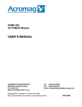
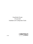
DE-220P
Installation Guide
Ethernet Card
Model DE-220P series
(DE-220PCAT, DE-220PCT DE-220PT)
Installation Guide
Rev.05(Jan. 1997)
6DE-220-P..-.05
Printed in China
WARRANTIES EXCLUSIVE
IF THE D-LINK PRODUCT DOES NOT OPERATE AS WARRANTED ABOVE
THE CUSTOMER’S SOLE REMEDY SHALL BE, AT D-LINK’S OPTION,
REPAIR OR REPLACEMENT. THE FOREGOING WARRANTIES AND
REMEDIES ARE EXCLUSIVE AND ARE IN LIEU OF ALL OTHER
WARRANTIES, EXPRESSED OR IMPLIED, EITHER IN FACT OR BY
OPERATION OF LAW, STATUTORY OR OTHERWISE, INCLUDING
WARRANTIES OF MERCHANTABILITY AND FITNESS FOR A PARTICULAR
PURPOSE. D-LINK NEITHER ASSUMES NOR AUTHORIZBS ANY OTHER
PERSON TO ASSUME FOR IT ANY OTHER LIABILITY IN CONNECTION
w i t h
INSTALLATION MAINTENANCE OR USE OF D-LINK’S
D-LINK SHALL NOT BE LIABLE UNDER THIS WARRANTY IF ITS TESTING
AND EXAMINATION DISCLOSE THAT THE ALLEGED DEFECT IN THE
PRODUCT DOES NOT EXIST OR WAS CAUSED BY THE CUSTOMER’S OR
ANY THIRD PERSON’S MISUSE, NEGLECT, IMPROPER INSTALLATION OR
TESTING, UNAUTHORIZED ATTEMPTS TO REPAIR, OR ANY OTHER
CAUSE BEYOND THE RANGE OF THE INTENDED USE, OR BY ACCIDENT,
FIRE. LIGHTNING OR OTHER HAZARD.
LIMITATION OF LlABlLlTY
IN NO EVENT WILL D-LINK BE LIABLE FOR ANY DAMAGES, INCLUDING
LOSS OF DATA, LOSS OF PROFITS, COST OF COVER OR OTHER
INCIDENTAL, CONSEQUENTIAL OR INDIRECT DAMAGES ARISING OUT
THE INSTALLATION, MAINTENANCE. USE, PERFORMANCE, FAILURE OR
INTERRUPTION OF A D- LINK PRODUCT, HOWEVER CAUSED AND ON
ANY THEORY OF LIABILITY. THIS LIMITATION WILL APPLY EVEN IF
D-LINK HAS BEEN ADVISED OF THE POSSIBILITY OF SUCH DAMAGE.
IF YOU PURCHASED A D-LINK PRODUCT IN THE UNITED STATES, SOME
STATES DO NOT ALLOW THE LIMITATION OR EXCLUSION OF LIABILITY
FOR INCIDENTAL OR CONSEQUENTIAL DAMAGES, SO THE ABOVE
LIMITATION MAY NOT APPLY TO YOU.
Limited Warranty
D-Link warrants its hardware products to be free from defects in workmanship and
materials, under normal use and service, for the following lengths of time from the
date of purchase from D-Link or its Authorized Reseller:
Product Type
Network adapters
Unmanaged and managed hubs
Repeaters, MAUs , transceivers, media converters
Concentrators
lntemetworking products
* Power supply and fans in these devices
Other hardware products
Spare parts and spare kits
Lifetime
Lifetime *
One year
One year
One year
One year
One year
90 days
If a product does not operate as warranted during the applicable warranty period ,
D-Lmk shall, at its option and expense, (1) repair the defective product as part, (2)
deliver to Customer an equivalent product or part to replace the defective item.All
products that are replaced will become the property of D-Link. Replacement products
may be new or reconditioned. Any replaced or repaired product or part has a ninety
(90) day warranty or the remainder of the initial warranty period, whichever is longer.
D-Link shall not be responsible for any software, fiiware, information, or memory
data of Customer contained in, stored on, or integrated with any products returned to
D-Link pursuant to any warranty.
All products with lifetime warranty have a standard five-year warranty. To qualify for
lifetime warranty, the enclosed Product Registration Card must be completed and
returned to D-Link within ninety (90) days of purchase.
Warranty service may be obtained by contacting a D-Link office within the applicable
warranty period for a Return Material Authorization (RMA) number. If a Registration
Card has not been previously sent, proof of purchase, such as a copy of the dated
purchase invoice, must be provided Once an RMA number is issued, the defective
product must be shipped back to D-Link prepaid, insured and wrapped in the original
or similar shipping package to ensure that it will not be damaged during shipment.
When returning the defective product to D-Link for service, the RMA number must
be marked on the outside of the shipping package. Any product returned without an
RMA number shah be rejected and sent back to the Customer, and D-Link reserves
the right to have Customer bear the cost of sending back such products. A service
charge may or may not be levied to Customer by D-Link. To find out if a service
charge IS levied or not, and the charged amount, read the RMA that is returned to
Customer, or ask the D-Link office when an RMA is requested.
D-Link Offices to Contact for Warranty
Service:
To mail your Registration Card, or to obtain an RMA number or a warranty service,
see the following addresses:
U.S.A.
CANADA
U.K.
FRANCE
SWEDEN
DENMARK
SINGAPORE
AUSTRALIA
CHINA
JAPAN
INDIA
TAIWAN
Trademarks
Copyright C D-Link Corporation.
Contents subject to revision without prior notice.
D-Link and LANsmart
Corporation.
are registered trademarks of D-Link
All other trademarks belong to their respective owners.
Copyright Statement
No part of this publication may be reproduced in any
any means or used to make any derivative (such as
transformation or adaptation) without permission from
Corporation/D-Link Systems Inc., as stipulated by
States Copyright Act of 1 976.
FCC
n
from or by
translation,
the D-Link
the United
CERTIFICATIONS
FCCID:
DE-220PCAT : KA2APC26OPl
DE-220PCT/PT : KA2APC26OPO
The device complies with Part 15 of the FCC Rules. Operation is
subject to the following two conditions: (1) this device may not
cause harmful interference, and (2) this device must accept any
interference received, including interference that may cause
undesired operation.
The equipment has been tested and found to comply with the limits
for a Class B digital device, pursuant to Port 15 of the FCC Rules.
These limits are designed to provide reasonable protection
against harmful interference when the equipment is operated in a
commercial environment. This equipment generates, uses, and
can radiate radio frequency energy and, if not installed and used
in accordance with the Instruction manual, may cause
interference in which case user will be required to correct the
interference at his own expense.
This product generates and used energy of about the same
frequency as radio and TV broadcasts. Installed incorrectly, it it
may interfere with reception of radio and TV broadcasts.
If you suspect this product is causing interference, turn your
computer on and off while the radio or TV is showing interference.
If the interference disappears when you;u turn the computer off
and reappears when you turn the computer on, something in the
computer is causing interference.
To reduce interference, try these suggestions:
-
Change the direction of the radio of TV antenna.
-
Move the computer, radio or TV. For example, if the computer
is to the right of the TV, move it to the left of the TV. Or move
them farther apart.
-
Plug the computer into a different electrical outlet than the
radio or TV.
ensure that all expansions slots (on the back or side of the
computer) are covered. Also ensure all metal retaining brackets
are tightly attached to the computer.
TABLE OF CONTENTS
INTRODUCTION ..............................................
l-l
Features ...........................................................
l-2
Overview of PnP ...............................................
l-5
INSTALLATION ................................................
2-7
Single-Adapter Installation
Multiple-Adapter Installation
................................
.2-8
..............................
.2-9
Multiple Cards in a PnP System ........................
2-10
Multiple Cards in a Non-PnP System ................ .2-10
Network Cable Connections ..............................
2-11
The Network Medium is Twisted-Pair Cable ...... 2-13
The Network Medium is Thin Coaxial Cable ..... ..2-14
The Network Medium is Thick Coaxial Cable .... .2-15
SPECIFICATIONS ............................................
2-16
Introduction
The D-Link DE-220P Series is a new line of Plug and
Play Ethernet, adapters based on the technology of DLinks best,-selling DE-220 Ethernet adapters. Plug
and Play (PnP) technology provides automatic configuration of newly installed devices without, user
intervention, eliminating much guess-work from installation of PC upgrades.
Ease of use is the hallmark of the DE-220P Series.
After installing a DE-220P Series card, configuration
is exceedingly simple for both traditional (non-PnP)
systems and the newer PnP-compliant, systems.
For PnP systems, simply install the DE-220P Series
card into an expansion slot. Configuration by the system software then proceeds automatically. If multiple
network interface cards are installed, the PnP system
guarantees that, there are no conflicts among them.
For non-PnP systems, just, install the DE-220P Series
adapter into an available expansion slot, then run the
supplied setup program, setup. exe. Online help answers your questions, and an advanced diagostic
DE-22OP Series Ethernet Adapter / User’s Guide
---_-_________-___-_--------------
program is supplied for testing adapter functions and
communication with other computers on the network.
Features
DE-220P Series Ethernet, adapters comply with IEEE
802.3 Ethernet standards, and use VLSI components
for enhanced reliability. The following features distinguish D-Link DE-220P Series Ethernet, adapters:
+ Easy Installation
DE-220P Series Ethernet, adapters have no
physical jumpers or DIP switches. Thus it, is
never necessary to remove a DE-220P Series card
in order to reconfigure. When installed in a PnPsystem , configuration is handled
compliant
e n t i r e l y b y system software, w i t h n o u s e r
configuration
intervention. In non-PnP systems,
is accomplished by running the supplied setup
program.
+
Support, for 8-bit, and 16-bit. Expansion Slots
DE-220P Series Ethernet, cards can be installed in
8-bit, (XT-style) or 16-bit (AT-style) expansion
slots. The adapter will automatically detect the
type of its expansion slot.
l-2
introduction
DF220P Series Ethernet Adapter / User’s Guide
_--~~--~~~----------~~-----~~----~
NE-2000 Drivers
DE-220P Series Ethernet adapters are fully
compatible with network drivers for Novell NE2000 adapters.
Diagnostic Program
A supplied diagnostic program tests all functions
of the DE-220P Series adapter and verifies its
communication with another computer on your
network.
LEDs
Two LEDs provide network
state information:
1. PWR/Tx Indicator
Steady green (Power indicator) shows that the
adapter has power (computer power is ON and
power is supplied to the adapter).
Flashing green (Transmission indicator) shows
that the computer is transmitting onto the network.
This function applies only when the
network medium is twisted-pair cable.’
’ See Footnote 5, Page 2-12.
Introduction
l-3
DE-22OP Series Ethernet Adapter / User’s Guide
____-----____----___-~~----------~
2. LNK/Rx indicator
Steady green (Linkage indicator) shows that there
is a good data linkage to the network.
Flashing green (Reception indicator) shows that,
the computer is receiving from the network. This
function applies only when the network medium is
twistsed-pair cable.’
+ Remote boot option
A Remote Boot, ROM is available per optional order. The Remote Boot ROM easily snaps into a
mount on the DE-220P Series card to provide for
remote booting of computers which do not, store a
boot. program.
+
Runs a wide variety of networking software
DE-220P Series Ethernet adapters can be used
with these networking systems:
l-4
D-Link LANsmart,
D-Link TCP/IP for DOS
NDIS driver
Novell NetWare 3.x and
4.x ODI driver
MS LAN Manager
Windows for Workgroups
Introduction
DE-22OP Series Ethernet Adapter / User’s Guide
_-______________------------------
Windows 95
Windows NT & Windows
NT Advanced Server
SUN PC-NFS
DEC Pathworks
Banyan VINES
IBM LAN Server & PC
LAN Support Program
Packet, Driver
3Com 3+0pen
3+Share
FTP PC/TCP
WIN/TCP Pathway Access for DOS
SC0 UNIX
AT&T UNIX
UNIXware
Solaris UNIX
& 3Com
Overview of PnP
Plug and Play technology (PnP) is defined by Plug and
Play ISA Specification v. l.Oa. A fully functional PnP
system includes a PnP-compliant, operating system, a
PnP system BIOS, and PnP-compliant, interface cards.
Windows 95 is the first popular PnP-compliant
operating system. Computer mainboards with PnP BIOS’s
are just reaching the market.
In the interim, PnP technology still provides substantial benefits. For example, after installing a non-PnPcompliant, Ethernet, adapter card (a traditional, nonPnP-compliant, card may be called a legacy card) into
Introduction
l-b
-DE-220P
- - - - Series
- - - Ethernet
- - - - -Adapter
- - - - /- User’s
- - - Guide
- - - - - - - - - - - - -
an expansion slot, of’ a PnP-compliant mainboard, the
user can run the ISA Configuration Utility (ICU) to
configure the adapter.
For some legacy cards, the user will need to set, DIP
switches or jumpers on the card to configure it. to the
system resources reported available by the ICU. With
other legacy cards like the D-Link DE-220 and DE220E, configuration is accomplished by running the
supplied setup program.
l-6
Introduction
DE-220P Series Ethernef Adopter / User’s Guide
---------_--_---------------------
Ins talla tion
CAUTION:
Under ordinary circumstances, a DE-220P
Series card will not be affected by static charge
as may be received through your body during
handling of the unit. In special circumstances
where you may carry an extraordinarily high
static charge, it is good practice to reduce the
charge by touching a ground before handling
the adapter.
Installation of a DE-220P Series Ethernet, adapter requires these three steps:
+ Install the adapter into an available expansion
slot,.
+
Connect, network cable to the adapter.
+ For non-PnP systems, configure the adapter by
running the supplied setup program, setup. exe.
(For PnP-compliant, systems,
this step is fully
automated and requires no action.)
This chapter provides detailed procedures for these
three steps. When these steps are completed, you may
Installation
2-7
DE-220P Series Ethernet Adapter / User’s Guide
---------------------------~~~~~~~
run the diagnostic routines of setup. exe program to
test the configuration.
Single-Adapter Installation
1.
Shut down the computer, unplug its power cord,
and remove the chassis cover.
2.
Insert the DE-220P Series card into the connector
of any open ISA expansion slot. You may choose
either an 8-bit or l6-bit, expansion slot,. A l6-bit,
slot, will provide better network performance. Ascertain that, the card is fully seated in the
expansion slot connector.
3.
Install the bracket, screw which secures the card
to the computer chassis.
4.
Replace the cornputer’s chassis cover.
5.
For non-PnP systems, configure the DE-220P Series adapter by running the supplied setup
program, setup. exe. (For PnP-compliant systems, this step is fully automated and requires no
action.)
2-8
Installation
- - - - - - - - - - - DE-22OP
- - - - Series
- - - -Ethernet
- - - -Adapter
- - - - /- User’s
- - - -Guide
- -
Multiple-Adapter Installation
Multiple DE-220P Series cards may be installed in
a computer to provide for multiple addresses, or in
the case of a server, to provide for network segmentation.
Multiple Cards in a PnP System
No special attention is needed when installing
multiple DE-220P Series cards in a PnP-compliant
system (so long as Plug and Play is enabled). Install the several cards into their expansion slots,
following the four steps set, out in the “SingleAdapter Installation” section above (repeating
steps 2 and 3 for each card). When computer
power is switched on, the PnP system will automatically
coordinated
(conflict,-free)
select
configuration settings for the several cards.
3 Pl ug and Play functionality of the NOS may be toggled between
enable and disable by a selection in your setup.exe run.
Installation
2-9
-DE-220P
- - - - Series
- - - Ethernet
- - - - -Adapter
- - - - /- User’s
- - - Guide
- - - - - - - - - - - - -
Multiple Cards in a Non-PnP
System
In non-PnP systems, the procedure for configuring
multiple DE-220P Series cards is basically a sequence of separate single-adapter procedures:
make a preliminary installation of each card alone
in turn: make a setup. exe run to configure that
card, then remove that card and go on to the next,.
CAUTION:
The following procedure involves operation of the
computer without its chassis housing in place.
Caution is necessary in order to avoid contact
Accidental
with exposed high-voltage parts.
contact with exposed internal parts can cause
personal injury and can cause damage to the
computer equipment.
Make a preliminary installation of the first, DE220P Series card by completing Steps 1 through 3
as set out. in the ‘Single-Adapter Installation” section above.
Restore power to the computer, and configure the
card by running the supplied setup program,
setup. exe.
Make a note of the configuration
settings that, you select, to help you select, different
settings in configuring the remaining cards.
Shut. down the computer and unplug its power
cord. Remove the (configured) card, and install
the
next. D E - 2 2 0 P
pansion
2-10
slot.
Series
i dn t o
anyopen ex-
DE-220P Series Ethernef Adapter / User’s Guide
__---_-______-__-__-______________
4.
Restore power to the computer. and configure the
card by running the supplied setup program,
setup. exe. Be certain that you select, different
configuration settings from those that, have been
selected for another card. Make a note of the configuration settings you select, to help you select
different settings in configuring remaining cards.
5
Repeat Steps 3 and 4 as necessary to configure all
DE-220P Series cards which are to be included in
the multiple-card installation.
6. Shut down the computer and unplug its powercord. Re-install all of the configured cards. Replace the computer’s chassis cover.
Network Cable Connections
Before connecting a network cable to the DE-220P
Series adapter, ascertain that your DE-220P model
suits your network cable medium, as summarized in
the following table.4 Then refer to one of the three
4
Models DE-220PCT and DE-22OPCAT
feature multiple network
cable connectors for convenience during network cable upgrades,
and for versatility when your equipment is moved between areas
with different types of network media. Only one network cable
may be connected to any adapter in any given installation.
Installation
2-11
DE-220P Series Ethernet Adapter / User’s Guide
-------_------_-----------~------~
sections following, according to your network cable
type.
Model
Network Cable Types
DE-220PT
Twisted-Pair5
DE-220PCT
Thin Coaxial’ and Twisted-Pair
DE-220PCAT
Thick Coaxial’. Thin Coaxial, and Twisted-Pair
5
6
only
Twisted-pair (TP) cable features RJ-45 connectors, and is available
with or without EM shield. TP cable without EM shield is. also
known as 1OBaseT cable or UTP (Unshielded Twisted-Pair) cable.
TP cable with EM shield is known as screened twisted-pair cable,
and the EM shield may be either an aluminum sheath or a copper
braid enclosing the twisted-pair bundle.
This medium features BNC connectors and is known by a variety
of other names. including lOBase2 cable, BNC cable, and RG-58
rable.
This medium features AUI connectors and is also known as
lOBase5 cable. It is sometimes called by names such as “frozen
yellow garden hose,” due to its bulk, weight, and stiffness.
2-12
Installation
- - - - - - - - - - -DE-220P
- - - - Series
- - - Ethernet
- - - - -Adapter
- - - - /- User’s
- - - Guide
- - -
The Network Medium is TwistedPair Cab/e
1. Ascertain that, you have a straight,* twistedpair cable not, more than 100 meters (328 feet)
in length for the network connection.
8
Pins 1 and 2 must be a pair (the connected wires must be a twisted
pair in the cable makeup) and pins 3 and 6 must he a pair. Each
pin must connect, straight through the rahle (that is pin 1 through
to pin 1 of the opposite connector. pin 2 to pin 2. pin 3 to pin 3, and
pin 6 to pin 6: pins 4.5. 7.8 are not, used).
Installation
2-13
DE-220P Series Ethernet Adapter / User’s Guide
---------_-------__---------------
2. The cable will have an RJ-45 plug on each
end. Plug one end into the RJ-45 receptacle of
the DE-220P Series adapter, and plug the
other end into an available port, of a lOBase-T
hub. Push each RJ-45 plug into its receptacle
until its retainer snaps into place.
The Network Medium is Thin
Coaxial Cable
1. Connect, a BNC T-connector onto the BNC receptacle of the DE-220P Series card.
2. Connect, the network feed cable onto either open
end of the BNC T-connector.
3a. If the cable continues on to an additional station
or stations, then connect. the continuation cable
onto the remaining open end of the BNC Tconnector.
3b. If the network cable does not, continue to additional stations (your computer is at, the end of the
cable), then connect, a 50-ohm terminator to the
remaining open end of the BNC T-conector.
2-14
/nsta//ation
DE-220P Series Ethernet Adopter / User’s Guide
_______---------------------------
BNC T-ccnnector
The Network Medium is Thick
Coaxial Cab/e
1. If there is no Ethernet transciever (tap) in
place for your computer’s station on the network cable, then install a transciever (not,
supplied).
2 Connect. one end of an AUI cable to the Ethernet, transceiver.
3.
Connect. the other end of the AUI cable to the
AUI connector of the DE-220PCAT.
Thick coaxial cable
Installation
2-15
DE-220P Series Ethernet Adapter / User’s Guide
- - - - - - - - - - - - - - - - - - - - - - - - - - - - - - - - - -
Specifications
Model:
AUI connector for
thick coaxial
BNC connector for
thin coaxial
RJ45 connector for
twisted-pair
CE / FCC Class B
Maximum power
consumption
Size (cm)
IRQ options
I/O Base Address
options
Boot ROM Size
Boot Base Address
options
LED Indicators
Operating Temp.
Storage Temp.
Humidity
2-16
DE-220PCAT
YES
DE-220PCT
NO
DE-220PT
NO
YES
YES
NO
YES
YES
YES
YES
YES
3.5 Watts
YES
1 Watt
3.5 Watts
240H, 260H, 280H, 2AOH, 2COH, 2EOH, 3OOH,
320H, 340H, 360H, 380H
16K (supplied per optional order)
C800H, CCOOH, WOO, D400H, D800H,
DCOOH
Power/TX (Green), Rx/Link (Green)
32°F to 131°F (0°C to 55°C)
-4F to 176°F (-20°C to 8OC)
10% to 90% non-condensing
Specifications